
10. Project: Flagpole Climber
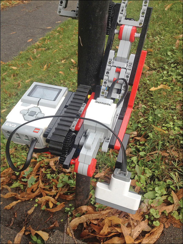
The final project of the book is the Flagpole Climber, an oddly-shaped robot built to roll up and down poles (see Figure 10.1). After you build the climber you program it in Mindstorms, and then you get to use a number of cool techniques you learned throughout the book to make the climber even better.

First, you add an old-school NXT ultrasonic sensor, a module no longer found in the standard Mindstorms EV3 set. Then you ditch the Intelligent Brick altogether and swap in a Raspberry Pi microcomputer (abbreviated RPi) and a Mindstorms-controlling BrickPi interface board, making the robot exponentially more powerful—at least computationally! Either way it’s a great learning experience.
Building the Flagpole Climber
The most notable thing about the Flagpole Climber might be its shape, with a 30-degree angle in the middle, the thought being to maximize the friction the wheels bear on the pole.
Parts List
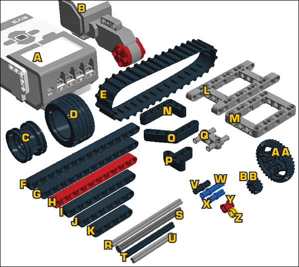
Begin by gathering together the following parts (see Figure 10.2):
A. 1x Intelligent Brick
B. 2x motors
C. 4x rims
D. 2x tires
E. 1x tank tread
F. 4x 15M beams
G. 4x 13M beams
H. 4x 11M beams (the red ones)
J. 2x 7M beams
K. 4x 5M beams
L. 2x 5x11 chassis bricks
M. 2x 5x7 chassis bricks
N. 3x 3x5 angle beams
O. 2x 4x4 angle beams
P. 2x 3x3 T-beams
Q. 8x 3M beams with pegs
R. 1x 9M cross axle
S. 3x 8M cross axles with end stop
T. 2x 6M cross axles
U. 1x 5M cross axle
V. 53 connector pegs
W. 14 3M connectors
X. 2 cross connectors
Y. 7 bushings
Z. 2 half bushings
AA. 2x Z36 gears
BB. 2x Z12 gears
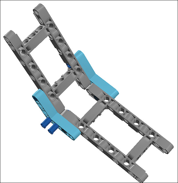
STEP 1 Begin by inserting two pegs, two cross connectors, and two 3M pegs into a pair of 5x11 chassis bricks. The angle at which the two bricks come together in Figure 10.3 is how they’ll be when attached; you do that in the next step!

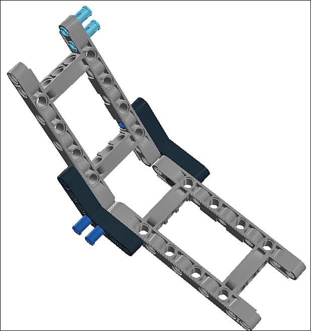
STEP 2 Secure the two frame bricks using 4x4 angle beams, as shown in Figure 10.4.
STEP 3 Add a couple of pegs to the end of the upper frame brick (see Figure 10.5).
STEP 4 Attach a 15M beam to the pegs, along with a couple of extra pegs. Figure 10.6 shows how your model should look.
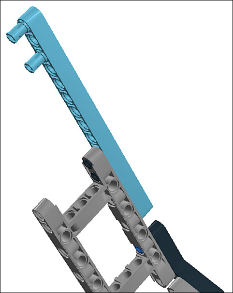
STEP 5 Add a 5x7 frame brick to the 15M beam, as shown in Figure 10.7.
STEP 6 Next, insert five pegs into the model (shown in Figure 10.8).
STEP 7 Attach another 15M beam to match the other (shown in Figure 10.9).

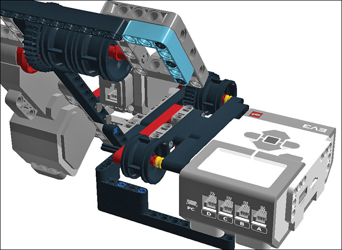
STEP 8 Insert a motor into the back of the upper frame brick and secure it with a pair of 8M axles with end stops. Note the bushings trapped in the middle of the motor mount! Those keep the axles from falling out. Figure 10.10 shows how it should look.

STEP 9 Put a motor on the lower frame brick and secure it with four 3M pegs, as shown in Figure 10.11.
STEP 10 Insert a 6M axle and bushing into the hub of the lower motor (shown in Figure 10.12).
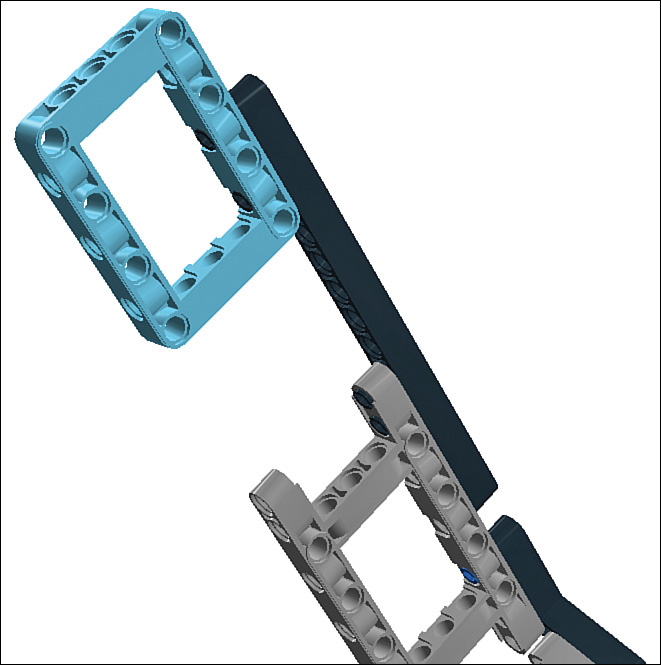
STEP 11 Place a 13M beam onto the exposed pegs, as well as the axle you just added (see Figure 10.13).
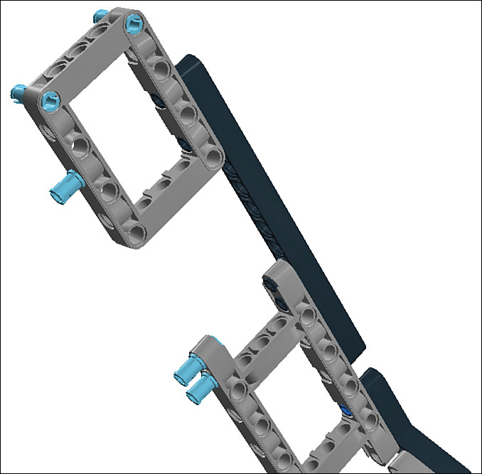
STEP 12 Add a couple more pegs, as shown in Figure 10.14.
STEP 13 Insert a 8M axle with end stop into the hub of the upper motor, trapping a pair of bushings (one on each side of the motor) along the way (see Figure 10.15).

STEP 14 Add Z12 gears to both axles, as shown in Figure 10.16.
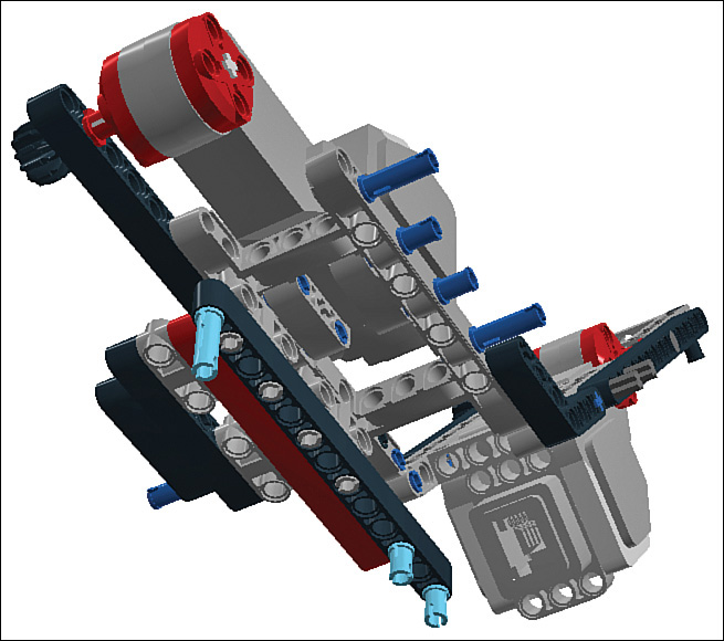
STEP 15 Add an 11M beam to the pegs (shown in Figure 10.17).

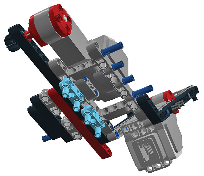
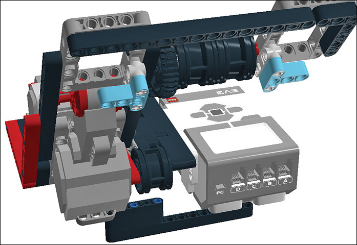
STEP 16 Add a pair of 3M beams with pegs, as shown in Figure 10.18.
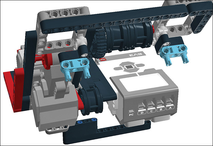
STEP 16 Attach a 7M beam, two pegs, and a 3M peg. Figure 10.19 shows how the climber should look.
STEP 18 Attach a 5M beam, as shown in Figure 10.20.

STEP 19 Attach a pair of 3M beams with pegs to the bottom of the frame brick, as shown in Figure 10.21.
STEP 20 Add a 13M beam. Figure 10.22 shows how it should look.

STEP 21 Insert two normal pegs and a 3M peg to the 13M beam you just added (shown in Figure 10.23).
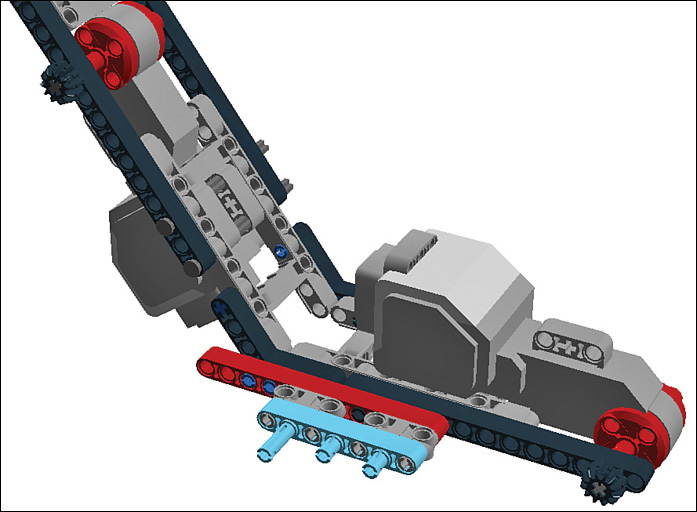
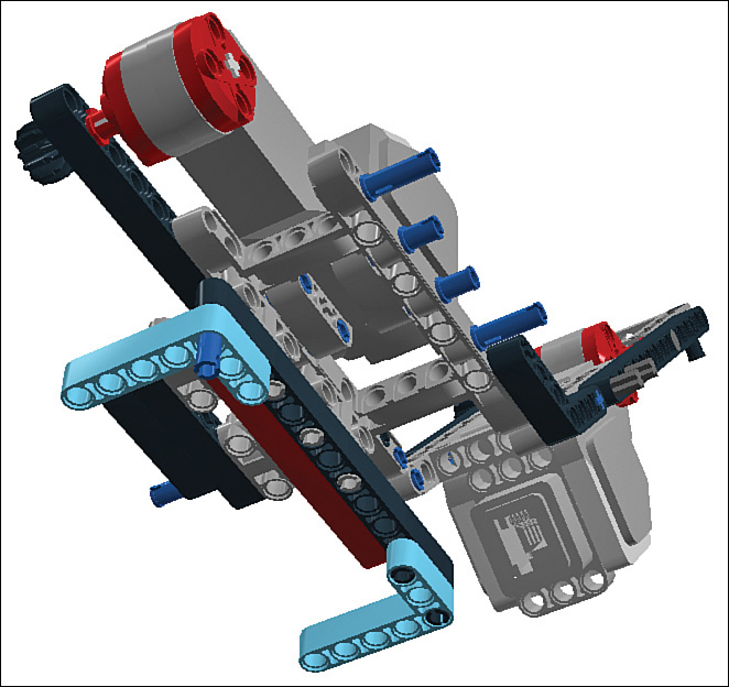
STEP 22 Add a pair of 3x5 angle beams to the underside of the climber, as shown in Figure 10.24.
STEP 23 Insert three normal and four 3M pegs to the angle beams, as shown in Figure 10.25.

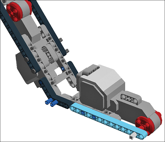
STEP 24 Add a pair of 5M beams. Figure 10.26 shows how it should look.
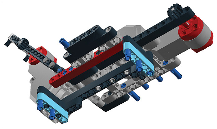
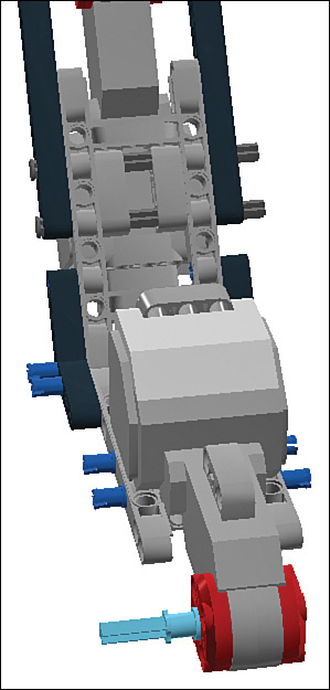
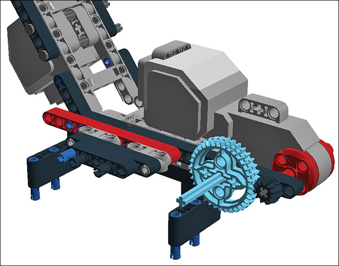
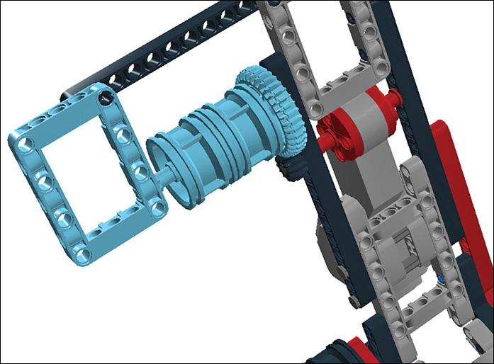
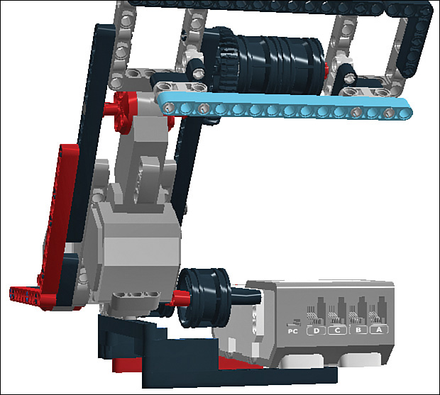
STEP 25 Insert a 6M axle and a Z36 gear such that the gear meshes with the smaller Z12 gear (as shown in Figure 10.27).
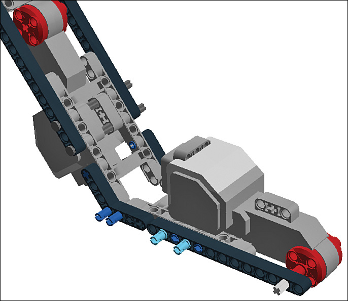
STEP 26 Insert a 6M axle into the red beam and add a half bushing. This will want to fall out, but just hold it in place with your finger (see Figure 10.28).

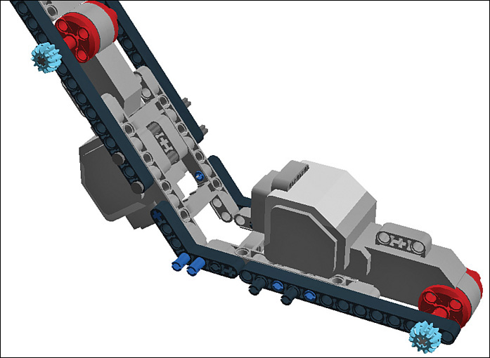
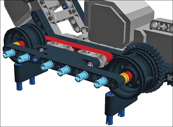
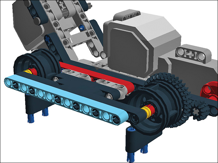
STEP 27 Attach rims to the two axles, as shown in Figure 10.29.
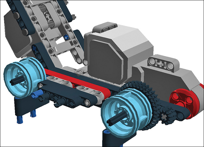
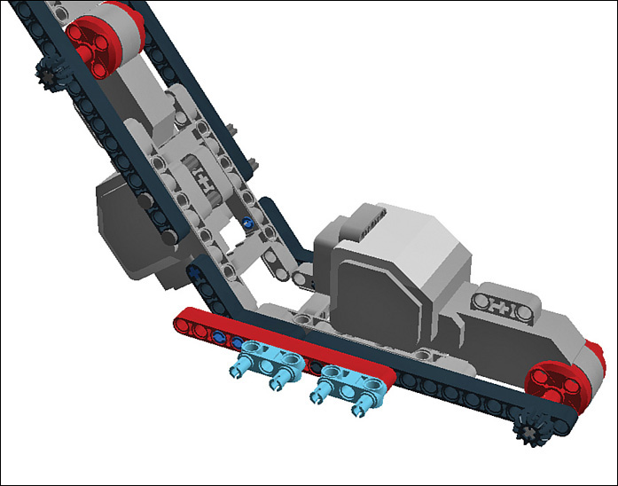
STEP 28 Secure the rims with one regular bushing and a half bushing. Figure 10.30 shows how it should look.

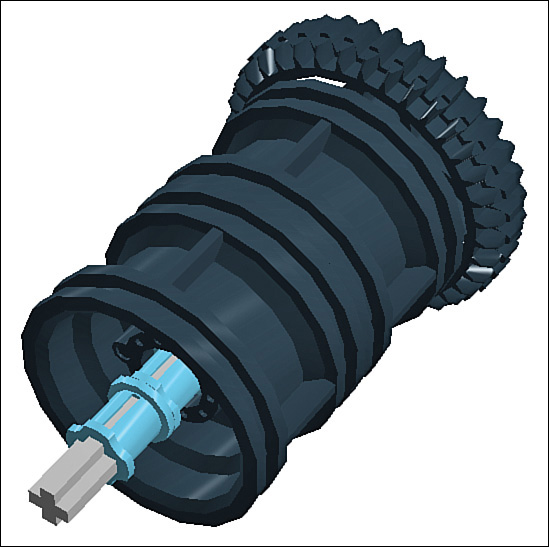
STEP 29 Put the tank treads on the robot. My design program doesn’t do treads very well, so here’s a photo that shows the tank treads on the finished robot (see Figure 10.31). If your treads don’t want to fit in, stretch it out a bit with your fingers, being careful not to pull too hard.

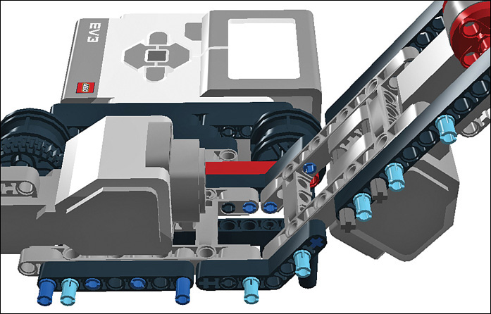
STEP 30 Add 5M and 9M beams to help stabilize the axles (see Figure 10.32).

STEP 31 Place six pegs on these new beams, spacing them as you see in Figure 10.33.
STEP 32 Throw on a 13M beam, shown in Figure 10.34.
STEP 33 Add three more pegs to the 13M beam, shown in Figure 10.35.

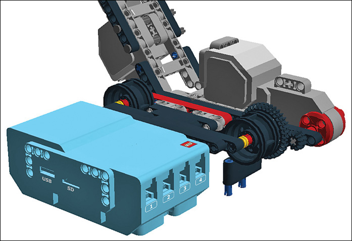
STEP 34 Attach the Intelligent Brick, as shown in Figure 10.36. Held on by only three pegs, the Brick is going to wobble, so keep it steady until it can be secured.
STEP 35 Add six pegs to the underside of the Intelligent Brick (see Figure 10.37).
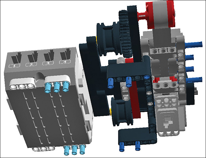
STEP 36 Attach 11M and 13M beams to the underside, as shown in Figure 10.38. Now the Intelligent Brick has some proper support!

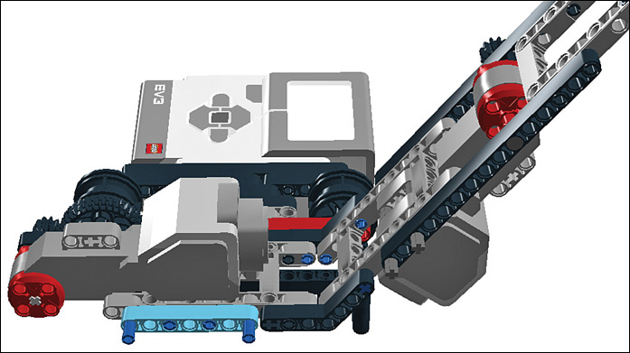
STEP 37 Add a 7M beam to the exposed pegs on the other side. Figure 10.39 shows how your robot should look.
STEP 38 Continuing on the same side, add six connector pegs as shown in Figure 10.40.
STEP 39 Attach a pair of 11M beams to the side of the climber (shown in Figure 10.41).

STEP 40 Connect a 15M beam to the other frame brick and throw in a peg while you’re at it (see Figure 10.42).
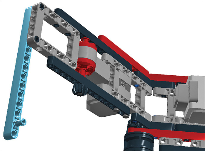
STEP 41 Let’s switch gears a moment (ha!) and work on the upper wheel assembly. Begin by adding a Z36 gear to a 7M axle, as shown in Figure 10.43.

STEP 42 Slide two rims onto the axle (shown in Figure 10.44).

STEP 43 Secure the rims with two bushings. The assembly should look like Figure 10.45.
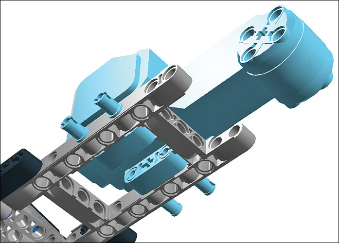
STEP 44 Connect one end of the wheel assembly so that the Z36 gear meshes with the Z12 gear attached to the motor. Trap the assembly with the help of a 5x7 chassis brick, which is attached to the 15M beam you added in Step 40. It should look like Figure 10.46.
STEP 45 Add three pegs to the underside of the chassis brick, as shown in Figure 10.47.

STEP 46 Attach a 3x5 angle beam to the pegs you just added (see Figure 10.48).
STEP 47 Add a pair of 3M beams with pegs to the undersides of the two 5x7 chassis bricks, as shown in Figure 10.49.

STEP 48 Attach a pair of T-beams, as shown in Figure 10.50.
STEP 49 Attach another pair of 3M beams with pegs. Figure 10.51 shows how it should look.
STEP 50 Finish up the robot’s basic build by adding a 15M beam, as shown in Figure 10.52.
Programming the Pole Climber
The basic Mindstorms program can’t get much simpler: The climber rolls up the pole a short distance and then back down again. This gets your feet wet for more intriguing applications, and this way you won’t get your robot stuck up a pole until you’re ready for the challenge!
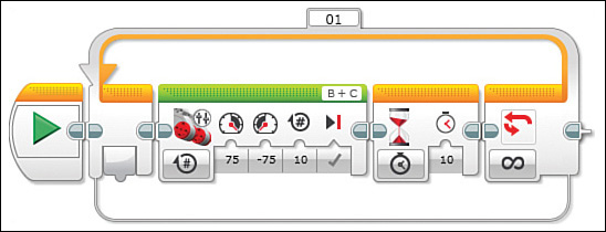
STEP 1 Begin with a Loop block and drop in a Move Tank block (see Figure 10.53). Set one motor to -75 power and leave the other at its default of 75. Then set rotations to 10.

STEP 2 Drop in a Wait block and set it to 10 seconds (Figure 10.54).
STEP 3 Add another Move Tank block, but reverse the speed settings (75 and -75) so that it will roll the other way. Add a second Wait block also set to 10 second delay. Figure 10.55 shows how the program should look.

Installing the Ultrasonic Sensor
As mentioned, the previous version of Mindstorms (NXT) included an ultrasonic sensor, a gadget that sends out inaudible “pings” consisting of sound waves and measures how fast they bounce back, thereby determining the distance to an obstruction. Here’s how to add this gadget to your robot:
STEP 1 Buy a sensor: You can still purchase them from LEGO, or they may be found at yard sales, on auction sites, or online retailers. http://shop.lego.com/en-US/Ultrasonic-Sensor-9846
STEP 2 Download the programming block: You can also find it on LEGO, on the Mindstorms downloads page at http://www.lego.com/en-us/mindstorms/downloads
STEP 3 From the EV3 software, select Tools and then Block Import. Browse to the folder where you put the block and then hit import. You need to reboot the software to see the new block.
STEP 4 Attach the sensor to the robot, using a 3x7 angle beam as pictured in Figure 10.56. This positions the sensor in a way that it’s pointing down when the robot’s climbing a pole. Connect the sensor to port 4 on the Intelligent Brick.
Programming the Sensor
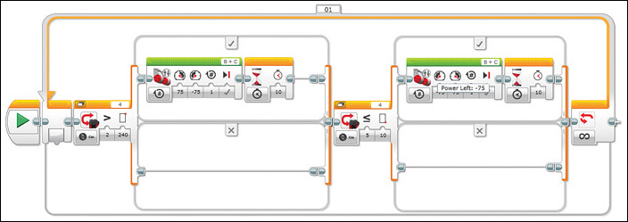
I decided to have a Switch block provide the main control mechanism for the ultrasonic sensor. The Switch moves the robot upward until the robot reaches 240cm (around 8 feet) in altitude. When that happens, the robot changes direction and rolls down until it is within 10cm of the ground, or around 4 inches. It’s a basic program that whets our appetite for more complexity!
1. Drag out a Switch block from the Flow Control palette and configure it to be triggered by the ultrasonic sensor, set to Compare and Measure Centimeters. Set it to trigger when the distance measured is less than or equal to 240cm.
2. Put a Move Tank block inside the top cell, as shown in Figure 10.57. Configure the Move Tank block as you did in the previous section. Also throw in a Wait block while you’re there, configured as before. The lower cell of the Switch remains empty.

3. After the main Switch, drop in another Switch, as shown in Figure 10.58. The first Switch runs the motors until the distance to the ground reaches 240cm, or about 8 feet. When that height is reached, the EV3 looks in the bottom cell to see what to do, and sees nothing: That Switch is done. The program moves on to the next Switch, which works the opposite way, rolling the robot downward until it reaches 10cm.
Swapping in the BrickPi
Suppose we swapped out the Intelligent Brick for another controller. In this case I’m talking about the Raspberry Pi microcomputer (see Figure 10.59), a board the size of a credit card that runs the Linux operating system. It can be controlled much the same way as an Arduino but is much more powerful. It can connect to the Internet, play movies, and more. You will learn how to use the RPi in conjunction with a BrickPi board to control the climber. First, however, I will briefly bring you up to speed on the Raspberry Pi.
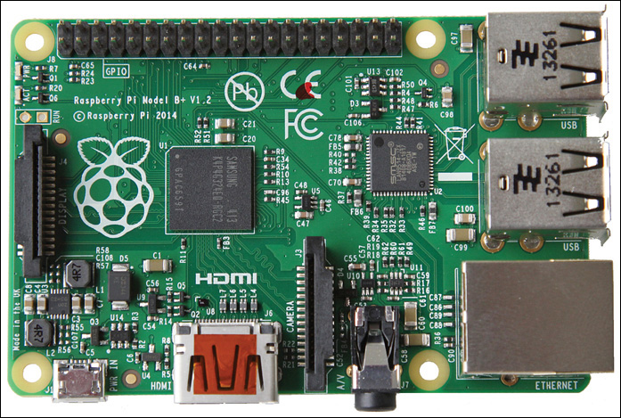
FIGURE 10.59 The Raspberry Pi microcomputer controls robots and a whole lot more! Credit: raspberrypi.org
Raspberry Pi Quick Start
This isn’t a Raspberry Pi book, so I can’t offer a full tutorial on the technology. However, I can get you started in the right direction. When in doubt, check out https://www.raspberrypi.org/, which is the product’s home organization.
1. Buy an RPi.
The RPi I used in this project is a Model B. You can purchase one from online retailers such as SparkFun Electronics (sparkfun.com, P/N 13297) and Adafruit Industries (Adafruit.com, P/N 2358).
2. Equip it.
You can buy accessories for the RPi from the same stores. You need a keyboard, mouse, and display to interface with the unit. In addition, you may want to buy sensors, switches, and other electronics to add on. Finally, many third-party boards—such as the BrickPi are available to add display options, motor control capability, and sensors onto the microcomputer. I get more into what you need to buy in the parts list that follows.
3. Load the OS.
Another thing to buy is a good SD card, upon which you load the operating system—though many sites offer pre-imaged SD cards for sale. Either way, the RPi’s operating system is resident on the card.
4. Program it.
There is actually a dizzying array of RPi programming options. It is, after all, effectively a small computer. Because it’s a computer, uploading a program works about the same way. How do you get a file onto your laptop? Plug in a flash drive, upload it over the network, or put it on the SD card. For this book I chose Python, a relatively simple programming language, to control the Mindstorms robot. You can learn more about Python at python.org.
5. Learn more.
Dexter Industries has a complete tutorial on installation (http://www.dexterindustries.com/BrickPi/getting-started/). In addition, SparkFun offers an exhaustive tutorial on installing the BrickPi that can be referenced on SparkFun.com: https://learn.sparkfun.com/tutorials/getting-started-with-the-brickpi.
Adding the RPi and BrickPi
Let’s do away with that trusty but limited Intelligent Brick and replace it with the RPi and a BrickPi interface board, along with a case to enclose everything. You can see the assembly pictured in Figure 10.60. The BrickPi interfaces between the RPi and Mindstorms motors and features sensor and motor plugs compatible with Mindstorms wires. So basically, it is similar to the Bricktronics Shield mentioned in Chapter 6, “Project: Robot Flower,” except for a different platform.

In addition to swapping in the RPi, you take advantage of the BrickPi’s Mindstorms compatibility to continue to run the ultrasonic sensor, and you wire in a combo barometric sensor, temperature sensor, and altimeter that gives the RPi more detailed information on what life at the top of a flagpole is like.
Parts List
Let’s go over what you need to rebuild your climber as a computer-controlled weather station!
![]() The Mindstorms robot you built earlier in the chapter, including the ultrasonic sensor.
The Mindstorms robot you built earlier in the chapter, including the ultrasonic sensor.
![]() Raspberry Pi Model B: The latest and greatest, at least at the time of this writing.
Raspberry Pi Model B: The latest and greatest, at least at the time of this writing.
![]() BrickPi: Buy it from dexterindustries.com.
BrickPi: Buy it from dexterindustries.com.
![]() MPL3115A2 Altimeter: Found at Adafruit.com, P/N 1893.
MPL3115A2 Altimeter: Found at Adafruit.com, P/N 1893.
![]() Female-to-male jumper wires: Adafruit.com, P/N 1954.
Female-to-male jumper wires: Adafruit.com, P/N 1954.
![]() The BrickPi acrylic case, http://www.dexterindustries.com/shop/brickpi-b-case/.
The BrickPi acrylic case, http://www.dexterindustries.com/shop/brickpi-b-case/.
![]() Battery pack, such as the one at http://www.dexterindustries.com/shop/brickpi-power-pack/.
Battery pack, such as the one at http://www.dexterindustries.com/shop/brickpi-power-pack/.
Steps
Follow these steps to add the Pi:
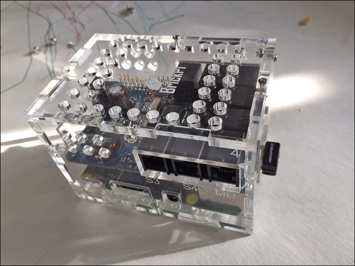
STEP 1 Build the case and install the RPi and BrickPi inside it (see Figure 10.61). Dexter Industries has a tutorial showing how to do this: http://www.dexterindustries.com/BrickPi/getting-started/basics/.
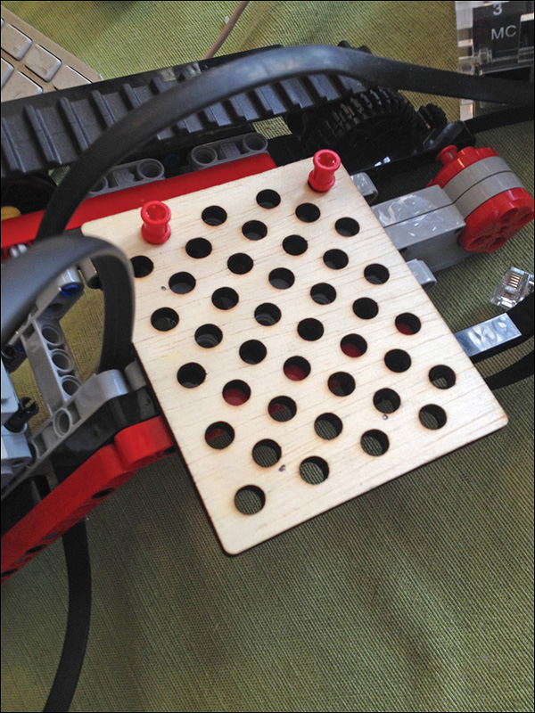
STEP 2 Attach the case to the robot using zip ties, metal hardware, or Mindstorms connector pegs. I used a laser-cut piece of wood with the RPi case screwed into it, shown in Figure 10.62. I then attached the wooden plate, which features Mindstorms hole spacing, onto the robot using 3M peg with cross hole elements.
STEP 3 Install the OS, which as mentioned, amounts to putting the OS on an SD card, shown in Figure 10.63. You must use Dexter Industries’ modified Raspbian image or the BrickPi won’t work. You can learn how to prep the SD card on Dexter’s site: http://www.dexterindustries.com/BrickPi/getting-started/pi-prep/.

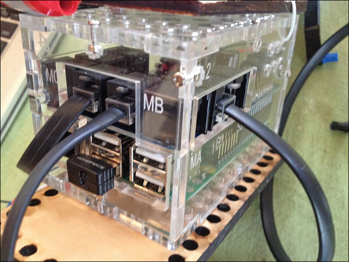
STEP 4 Plug the Mindstorms wires into the BrickPi, including the ultrasonic sensor wire into port S2, as well as the motors into MB and MC (see Figure 10.64).
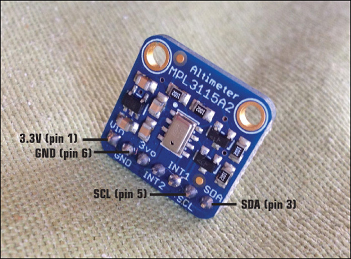
STEP 5 Wire up the altimeter as shown in Figure 10.65. Plug the Vin pin into 3.3V (pin 1) on the BrickPi. Plug the altimeter pin marked SDA into pin 3 on the BrickPi, and the SCL pin into pin 5 on the BrickPi. Finally, Connect GND to GND (pin 6) to ground the sensor.
STEP 6 Add the battery pack, shown in Figure 10.66. I mounted mine on a wooden plate with Technic-spacing holes, making it easier to mate LEGO and non-LEGO parts. The pack just plugs into the RPI’s power plug.

STEP 7 Program the Climber. Place the following program on the Raspberry Pi and launch it to begin operation. Figure 10.67 shows the finished robot in operation!

#thanks to Dexter Industries and CIAduck for their code examples.
#!/usr/bin/env python
from BrickPi import * #import BrickPi.py file to use BrickPi operations
BrickPiSetup() # setup the serial port for communication
BrickPi.SensorType[PORT_1] = TYPE_SENSOR_ULTRASONIC_CONT #Set the type of sensor at PORT_1
BrickPi.MotorEnable[PORT_A] = 1 #Enable the Motor A
BrickPi.MotorEnable[PORT_B] = 1 #Enable the Motor B
BrickPiSetupSensors() #Send the properties of sensors to BrickPi
power = 0
while True:
# print "Running Forward"
BrickPi.MotorSpeed[PORT_A] = 200
BrickPi.MotorSpeed[PORT_B] = -200
ot = time.time()
while(time.time() - ot < 3): #running while loop for 3 seconds
result = BrickPiUpdateValues() # Ask BrickPi to update values
for sensors/motors
time.sleep(.1) #pause a moment
from smbus import SMBus
import time
# Special Chars
deg = u'N{DEGREE SIDN}'
# I2C Constants
ADDR = 0x60
CTRL_REG1 = 0x26
PT_DATA_CFG = 0x13
bus = SMBus(1)
who_am_i = bus.read_byte_data(ADDR, 0x0C)
print hex(who_am_i)
if who_am_i != 0xc4:
print "Device not active."
exit(1)
# Set oversample rate to 128
setting = bus.read_byte_data(ADDR, CTRL_REG1)
newSetting = setting | 0x38
bus.write_byte_data(ADDR, CTRL_REG1, newSetting)
# Enable event flags
bus.write_byte_data(ADDR, PT_DATA_CFG, 0x07)
# Toggel One Shot
setting = bus.read_byte_data(ADDR, CTRL_REG1)
if (setting & 0x02) == 0:
bus.write_byte_data(ADDR, CTRL_REG1, (setting | 0x02))
# Read sensor data
print "Waiting for data..."
status = bus.read_byte_data(ADDR,0x00)
while (status & 0x08) == 0:
# print bin(status)
status = bus.read_byte_data(ADDR,0x00)
time.sleep(0.5)
print "Reading sensor data..."
p_data = bus.read_i2c_block_data(ADDR,0x01,3)
t_data = bus.read_i2c_block_data(ADDR,0x04,2)
status = bus.read_byte_data(ADDR,0x00)
print "status: "+bin(status)
p_msb = p_data[0]
p_csb = p_data[1]
p_lsb = p_data[2]
t_msb = t_data[0]
t_lsb = t_data[1]
pressure = (p_msb << 10) | (p_csb << 2) | (p_lsb >> 6)
p_decimal = ((p_lsb & 0x30) >> 4)/4.0
celsius = t_msb + (t_lsb >> 4)/16.0
fahrenheit = (celsius * 9)/5 + 32
print "Pressure and Temperature at "+time.strftime('%m/%d/%Y %H:%M:%S%z')
print str(pressure+p_decimal)+" Pa"
print str(celsius)+deg+"C"
print str(fahrenheit)+deg+"F"
print "Running Backward"
BrickPi.MotorSpeed[PORT_A] = -200
BrickPi.MotorSpeed[PORT_B] = 200
ot = time.time()
while(time.time() - ot < 3): #running while loop for 3 seconds
BrickPiUpdateValues() # Ask BrickPi to update values for
sensors/motors
time.sleep(.1) # sleep for 100 ms
Tip: Troubleshooting
The following are some tips to ensure your climber works well:
1. The first thing to remember about the climber is that it relies on friction to work. If the flagpole in question has a smooth or wet surface you may need to either choose another pole or adapt the design.
2. The climber also relies on balance to keep the wheels on the metal. Try to keep the robot’s center of gravity on the same axis as the pole or the robot will tip to one side and ultimately fall off the pole.
3. Finally, flagpole diameter does play a role in the successful operation of the robot. The climber must hang correctly to maximize the friction it brings to bear on the pole. Try different diameters until you find the one the robot likes.
Summary
This chapter was all about combining different techniques from the book: The Intelligent Brick was swapped out for a Raspberry Pi, the mounting plate I used for the BrickPi enclosure was laser-cut out of wood, and the robot made use of an NXT ultrasonic sensor as well as a third-party electronic barometer.
That’s it for the book as well—thanks for reading it!