


Reliability, availability, and serviceability on the IBM DS8880
This chapter describes the reliability, availability, and serviceability (RAS) characteristics of the IBM DS8880.
This chapter covers the following topics:
3.1 DS8880 processor complex features
Reliability, availability, and serviceability are important concepts in the design of the IBM DS8880. Hardware features, software features, design considerations, and operational guidelines all contribute to make the DS8880 reliable. At the heart of the DS8880 is a pair of POWER8 processor-based servers. These servers, which are known as central processor complexes (CPCs), share the load of receiving and moving data between the attached hosts and the storage arrays. However, they are also redundant so that if either CPC fails, the system switches to the remaining CPC and continues to run without any host I/O interruption. This section looks at the RAS features of the CPCs, including the hardware, the operating system, and the interconnections.
3.1.1 POWER8 Hypervisor
The POWER8 Hypervisor (PHYP) is a component of system firmware that is always active, regardless of the system configuration, even when it is disconnected from the Management Console. PHYP runs on the flexible service processor (FSP). It requires the FSP processor and memory to support the resource assignments to the logical partition (LPAR) on the server. It operates as a hidden partition with no CPC processor resources that are assigned to it, but it does allocate a small amount of memory from the partition.
The PHYP provides the following capabilities:
•Reserved memory partitions set aside a portion of memory to use as cache and a portion to use as nonvolatile storage (NVS).
•Preserved memory support allows the contents of the NVS and cache areas to be protected if a server restarts.
•I/O enclosure initialization, power control, and slot power control prevent a CPC that is rebooting from initializing an I/O adapter that is in use by another server.
•It provides automatic restart of a hung or stopped partition. The PHYP also monitors the service processor and runs a reset or reload if it detects the loss of the service processor. It notifies the operating system if the problem is not corrected.
The AIX operating system uses PHYP services to manage the Translation Control Entry (TCE) tables. The operating system communicates the wanted I/O bus address to logical mapping, and the PHYP returns the I/O bus address to physical mapping within the specific TCE table. The PHYP needs a dedicated memory region for the TCE tables to translate the I/O address to the partition memory address. The PHYP then can monitor direct memory access (DMA) transfers to the Peripheral Component Interconnect Express (PCIe) adapters.
3.1.2 POWER8 processor
The IBM POWER8 processor implements 64-bit IBM Power Architecture® technology and represents a leap forward in technology achievement and associated computing capability. The multi-core architecture of the POWER8 processor modules is matched with innovation across a wide range of related technologies to deliver leading throughput, efficiency, scalability, and RAS.
Areas of innovation, enhancement, and consolidation
The POWER8 processor represents an important performance increase compared to previous generations. The POWER8 processor features the following areas of innovation, enhancement, and consolidation:
•On-chip L3 cache that is implemented in embedded dynamic random access memory (eDRAM), which improves latency and bandwidth. Lower energy consumption and a smaller physical footprint are benefits.
•Cache hierarchy and component innovation.
•Advances in memory subsystem.
•Advances in off-chip signaling.
•The POWER8 processor features intelligent threads that can vary based on the workload demand. The system automatically selects whether a workload benefits from dedicating as much capability as possible to a single thread of work, or if the workload benefits more from spreading the capability across two or four threads of work. With more threads, the POWER8 processor can deliver more total capacity as more tasks are accomplished in parallel. With fewer threads, those workloads that need fast individual tasks can get the performance that they need for maximum benefit.
The remainder of this section describes the RAS features of the POWER8 processor. These features and abilities apply to the DS8880. You can read more about the POWER8 and processor configuration, from the DS8880 architecture point of view, in 2.3.1, “IBM POWER8-based servers” on page 33.
POWER8 RAS features
The following sections describe the RAS leadership features of IBM POWER8 systems.
POWER8 processor instruction retry
As with previous generations, the POWER8 processor can run processor instruction retry and alternative processor recovery for many core-related faults. This ability significantly reduces exposure to permanent and intermittent errors in the processor core.
With the instruction retry function, when an error is encountered in the core in caches and certain logic functions, the POWER8 processor first automatically retries the instruction. If the source of the error was truly transient, the instruction succeeds and the system can continue normal operation.
POWER8 alternative processor retry
Hard failures are more difficult because permanent errors are replicated each time that the instruction is repeated. Retrying the instruction does not help in this situation because the instruction continues to fail. Similar to the IBM POWER6+™, POWER7®, and POWER7+ processors, the POWER8 processors can extract the failing instruction from the faulty core and retry it elsewhere in the system for many faults. The failing core is then dynamically unconfigured and scheduled for replacement. The entire process is transparent to the partition that owns the failing instruction. Systems with POWER8 processors are designed to avoid a full system outage.
POWER8 cache protection
Processor instruction retry and alternative processor retry protect processor and data caches. L1 cache is divided into sets. The POWER8 processor can deallocate all but one set before a Processor Instruction Retry is run. In addition, faults in the Segment Lookaside Buffer (SLB) array are recoverable by the IBM POWER® Hypervisor. The SLB is used in the core to run address translation calculations.
The L2 and L3 caches in the POWER8 processor are protected with double-bit detect single-bit correct error correction code (ECC). Single-bit errors are corrected before they are forwarded to the processor, and they are then written back to L2 or L3.
In addition, the caches maintain a cache line delete capability. A threshold of correctable errors that is detected on a cache line can result in purging the data in the cache line and removing the cache line from further operation without requiring a restart. An ECC uncorrectable error that is detected in the cache can also trigger a purge and delete of the cache line. This action results in no loss of operation because an unmodified copy of the data can be held in system memory to reload the cache line from main memory. Modified data is handled through special uncorrectable error handling. L2 and L3 deleted cache lines are marked for persistent deconfiguration on subsequent system restarts until they can be replaced.
POWER8 first-failure data capture
First-failure data capture (FFDC) is an error isolation technique. FFDC ensures that when a fault is detected in a system through error checkers or other types of detection methods, the root cause of the fault is captured without the need to re-create the problem or run an extended tracing or diagnostics program.
For most faults, a good FFDC design means that the root cause is detected automatically without intervention by a service representative. Pertinent error data that relates to the fault is captured and saved for analysis. In hardware, FFDC data is collected from the fault isolation registers and the associated logic. In firmware, this data consists of return codes, function calls, and so on.
FFDC check stations are carefully positioned within the server logic and data paths to ensure that potential errors can be identified quickly and accurately tracked to a field-replaceable unit (FRU).
This proactive diagnostic strategy is a significant improvement over the classic, less accurate restart and diagnose service approach.
Redundant components
High opportunity components (those components that most effect system availability) are protected with redundancy and the ability to be repaired concurrently.
The use of the following redundant components allows the system to remain operational:
•POWER8 cores, which include redundant bits in L1 instruction and data caches, L2 caches, and L2 and L3 directories
•Both the Power System S824 and S822 use CPC main memory and CDIMMs, which use an innovative ECC algorithm from IBM research that improves single-bit error correction and memory failure identification
•Redundant cooling
•Redundant power supplies
•Redundant 16x loops to the I/O subsystem
Self-healing
For a system to be self-healing, it must be able to recover from a failing component by detecting and isolating the failed component. The system is then able to take the component offline, fix, or isolate it, and then reintroduce the fixed or replaced component into service without any application disruption. Self-healing technology includes the following examples:
•Bit steering to redundant memory if a memory module failed to keep the server operational.
•Chipkill, which is an enhancement that enables a system to sustain the failure of an entire DRAM chip. An ECC word uses 18 DRAM chips from two DIMM pairs, and a failure on any of the DRAM chips can be fully recovered by the ECC algorithm. The system can continue indefinitely in this state with no performance degradation until the failed DIMM can be replaced.
•Single-bit error correction by using ECC without reaching error thresholds for main, L2, and L3 cache memory.
•L2 and L3 cache line delete capability, which provides more self-healing.
•ECC extended to inter-chip connections on the fabric and processor bus.
•Hardware scrubbing is a method that is used to address intermittent errors. IBM POWER8 processor-based systems periodically address all memory locations. Any memory locations with a correctable error are rewritten with the correct data.
•Dynamic processor deallocation.
Memory reliability, fault tolerance, and integrity
POWER8 uses ECC circuitry for system memory to correct single-bit memory failures. In POWER8, an ECC word consists of 72 bytes of data. Of these bytes, 64 are used to hold application data. The remaining 8 bytes are used to hold check bits and more information about the ECC word. This innovative ECC algorithm from IBM research works on DIMM pairs on a rank basis. With this ECC code, the system can dynamically recover from an entire DRAM failure (Chipkill). It can also correct an error even if another symbol (a byte, which is accessed by a 2-bit line pair) experiences a fault. This feature is an improvement from the Double Error Detection/Single Error Correction ECC implementation on the POWER6+ processor-based systems.
The memory DIMMs also use hardware scrubbing and thresholding to determine when memory modules within each bank of memory must be used to replace modules that exceeded their threshold of error count (dynamic bit-steering). Hardware scrubbing is the process of reading the contents of the memory during idle time and checking and correcting any single-bit errors that accumulated by passing the data through the ECC logic. This function is a hardware function on the memory controller chip, and does not influence normal system memory performance.
Fault masking
If corrections and retries succeed and do not exceed threshold limits, the system remains operational with full resources, and no external administrative intervention is required.
Mutual surveillance
The service processor monitors the operation of the IBM POWER Hypervisor™ firmware during the boot process and monitors for loss of control during system operation. It also allows the POWER Hypervisor to monitor service processor activity. The service processor can take the correct action (including calling for service) when it detects that the POWER Hypervisor firmware lost control. The POWER Hypervisor can also request a service processor repair action, if necessary.
3.1.3 AIX operating system
Each CPC is a server that runs the IBM AIX Version 7.1 operating system (OS). This OS is the IBM well-proven, scalable, and open standards-based UNIX-like OS. This version of AIX includes support for Failure Recovery Routines (FRRs).
For more information about the features of the IBM AIX operating system, see this website:
3.1.4 Cross-cluster communication
In the DS8880, the I/O enclosures are connected point-to-point and each CPC uses a PCIe architecture. DS8880 uses the PCIe paths between the I/O enclosures to provide the cross-cluster (XC) communication between CPCs. This configuration means that no separate path is between the XC communications and I/O traffic, which simplifies the topology. During normal operations, the XC communication traffic uses a small portion of the overall available PCIe bandwidth (less than 1.7%), so XC communication traffic has a negligible effect on I/O performance.
Figure 3-1 shows the redundant PCIe fabric design for XC communication in the DS8880. If the I/O enclosure that is used as the XC communication path fails, the system automatically uses an available alternative I/O enclosure for XC communication.
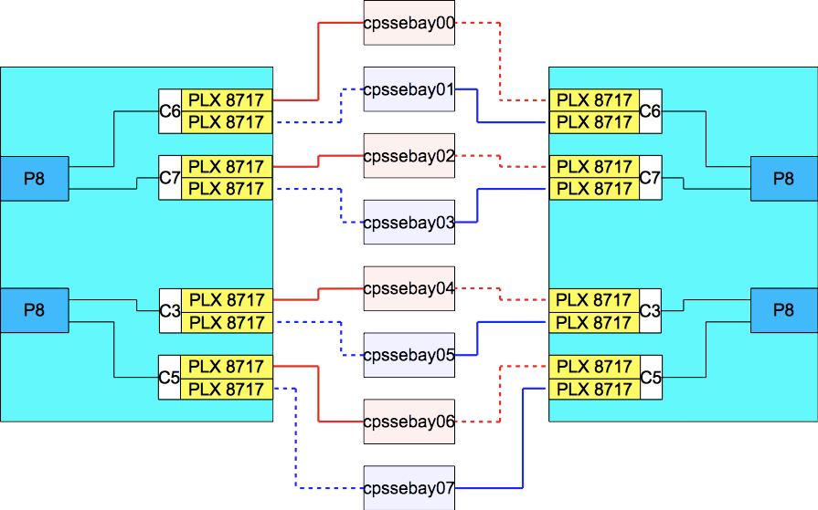
Figure 3-1 DS8886 XC communication through the PCIe fabric and I/O enclosures
3.1.5 Environmental monitoring
The environment (power, fans, and temperature) is monitored by the FSP. Environmental critical and non-critical conditions generate emergency power-off warning (EPOW) events. Critical events (for example, a complete input power loss) trigger the correct signals from the hardware to start an emergency shutdown to prevent data loss without operating system or firmware involvement. Non-critical environmental events are logged and reported by using Event Scan.
The temperature is also monitored. If the ambient temperature rises above a preset operating range, the rotational speed of the cooling fans increases. Temperature monitoring also warns the Licensed Internal Code (LIC) of potential environmental problems. An orderly system shutdown, including a service call to IBM, occurs when the operating temperature exceeds a critical level.
Voltage monitoring provides a warning and an orderly system shutdown when the voltage is out of the operational specification range.
Additional monitoring support can be found with DSCLI showsu command by using the Added Energy Report Test Mode, ER Recorded, ER Power Usage, ER Inlet Temp, ER I/O Usage, and ER Data Usage fields.
3.1.6 Resource unconfiguration
If recoverable errors exceed threshold limits, resources can be unconfigured to keep the system operational. This ability allows deferred maintenance at a more convenient time. Dynamic deconfiguration of potentially failing components is nondisruptive, which allows the system to continue to run. Persistent deconfiguration occurs when a failed component is detected. It is then deactivated on a subsequent restart.
Dynamic deconfiguration functions include the following components:
•Processor
•L3 cache lines
•Partial L2 cache deconfiguration
•PCIe bus and slots
Persistent deconfiguration functions include the following components:
•Processor
•Memory
•Unconfigure or bypass failing I/O adapters
•L2 cache
After a hardware error that is flagged by the service processor, the subsequent restart of the processor complex starts extended diagnostic testing. If a processor or memory is marked for persistent deconfiguration, the boot process attempts to proceed to completion with the faulty device automatically unconfigured. Failing I/O adapters are unconfigured or bypassed during the boot process.
3.2 CPC failover and failback
To understand the process of CPC failover and failback, the logical construction of the DS8880 must be reviewed. For more information, see Chapter 4, “Virtualization concepts” on page 93.
3.2.1 Dual cluster operation and data protection
For processing host data, a basic premise of RAS is that the DS8880 always tries to maintain two copies of the data while the data moves through the storage system. Two areas of the primary memory of the nodes are used for holding host data: Cache memory and NVS. NVS for DS8886 is 1/16 of system memory with a minimum of 8 GB total on most configurations. For a DS8886 with 2 TB of total system memory, NVS is 1/32 of system memory (64 GB). For DS8884, all configurations use 1/16 of system memory for a minimum of 4 GB of NVS. NVS contains write data until the data is destaged from cache to the drives. NVS data is written to the CPC hard disk drives (HDDs) in an emergency shutdown due to a complete loss of input AC power.
When a write is sent to a volume and both the nodes are operational, the write data is placed into the cache memory of the owning node and into the NVS of the other processor complex. The NVS copy of the write data is accessed only if a write failure occurs and the cache memory is empty or possibly invalid. Otherwise, the NVS copy of the write data is discarded after the destage from cache to the drives is complete.
The location of write data when both CPCs are operational is shown in Figure 3-2.

Figure 3-2 Write data when CPCs are both operational
Figure 3-2 shows how the cache memory of node 0 in CPC0 is used for all logical volumes that are members of the even logical subsystems (LSSs). Likewise, the cache memory of node 1 in CPC1 supports all logical volumes that are members of odd LSSs. For every write that is placed into cache, a copy is placed into the NVS memory that is in the alternative node. Therefore, the following normal flow of data for a write when both CPCs are operational is used:
1. Data is written to cache memory in the owning node. At the same time, data is written to NVS memory of the alternative node.
2. The write operation is reported to the attached host as completed.
3. The write data is destaged from the cache memory to a drive array.
4. The write data is discarded from the NVS memory of the alternative node.
Under normal operation, both DS8880 nodes are actively processing I/O requests. The following sections describe the failover and failback procedures that occur between the CPCs when an abnormal condition affects one of them.
3.2.2 Failover
In the example that is shown in Figure 3-3, CPC0 failed. CPC1 needs to take over all of the CPC0 functions. All storage arrays are accessible by both CPCs.

Figure 3-3 CPC0 failover to CPC1
At the moment of failure, node 1 in CPC1 includes a backup copy of the node 0 write data in its own NVS. From a data integrity perspective, the concern is the backup copy of the node 1 write data, which was in the NVS of node 0 in CPC0 when it failed. Because the DS8880 now has only one copy of that data (active in the cache memory of node 1 in CPC1), it performs the following steps:
1. Node 1 destages the contents of its NVS (the node 0 write data) to the drive subsystem. However, before the actual destage and at the beginning of the failover, the following tasks occur:
a. The surviving node starts by preserving the data in cache that was backed up by the failed CPC NVS. If a restart of the single working CPC occurs before the cache data is destaged, the write data remains available for subsequent destaging.
b. The existing data in cache (for which still only a single volatile copy exists) is added to the NVS so that it remains available if the attempt to destage fails or a server restart occurs. This function is limited so that it cannot consume more than 85% of NVS space.
2. The NVS and cache of node 1 are divided in two, half for the odd LSSs and half for the even LSSs.
3. Node 1 begins processing the I/O for all the LSSs, taking over for node 0.
This entire process is known as a failover. After failover, the DS8880 operates as shown in Figure 3-3. Node 1 now owns all the LSSs, which means all reads and writes are serviced by node 1. The NVS inside node 1 is now used for both odd and even LSSs. The entire failover process is transparent to the attached hosts.
The DS8880 can continue to operate in this state indefinitely. No functionality is lost but the redundancy is lost, and performance is decreased because of the reduced system cache. Any critical failure in the working CPC renders the DS8880 unable to serve I/O for the arrays. Because of this failure, the IBM Support team must begin work immediately to determine the scope of the failure and to build an action plan to restore the failed CPC to an operational state.
3.2.3 Failback
The failback process always begins automatically when the DS8880 determines that the failed CPC resumed to an operational state. If the failure was relatively minor and recoverable by the DS8880 operating system, the software starts the resume action. If a service action occurred and hardware components were replaced, the IBM service support representative (SSR) or remote support engineer resumes the failed CPC.
This example in which CPC0 failed assumes that CPC0 was repaired and resumed. The failback begins with server 1 in CPC1 starting to use the NVS in node 0 in CPC0 again, and the ownership of the even LSSs being transferred back to node 0. Normal I/O processing, with both CPCs operational, then resumes. Just like the failover process, the failback process is transparent to the attached hosts.
In general, recovery actions (failover or failback) on the DS8880 do not affect I/O operation latency by more than 8 seconds.
If you require real-time response in this area, contact IBM to determine the latest information about how to manage your storage to meet your requirements.
3.2.4 NVS and power outages
During normal operation, the DS8880 preserves write data by storing a duplicate in the NVS of the alternative CPC. To ensure that this write data is not lost because of a power event, the DS8880 direct current uninterruptible power supplies (DC-UPSs) contain Battery Service Module (BSM) sets. The BSM sets provide continuity of power during AC power loss that is long enough for the CPCs to write modified data to their internal hard disks. The design is to not move the data from NVS to the disk arrays. Instead, each CPC features dual internal disks that are available to store the contents of NVS.
|
Important: Unless the extended power-line disturbance (ePLD) feature is installed, the BSM sets ensure storage operation for up to 4 seconds in a power outage. After this period, the BSM sets keep the CPCs and I/O enclosures operable long enough to write NVS contents to internal CPC hard disks. The ePLD feature can be ordered so that drive operations can be maintained for 40 seconds after a power disruption.
|
If any frames lose AC input (which is known as wall power or line power) to both DC-UPSs, the CPCs are informed that they are running on batteries. In continuous power unavailability for 4 seconds, the CPCs begin a shutdown procedure, which is known as an on-battery condition. It is during this emergency shutdown that the entire contents of NVS are written to the CPC HDDs so that the write data will be available for destaging after the CPCs are operational again.
If power is lost to a single DC-UPS, the partner DC-UPS provides power to this UPS, and the output power to other DS8880 components remains redundant.
The following sections describe the steps that are used if dual AC power is lost to the entire frame.
Power loss
When an on-battery condition shutdown begins, the following events occur:
1. All host adapter I/O is blocked.
2. Each CPC begins copying its NVS data to internal disk (not the storage drives). For each CPC, two copies are made of the NVS data. This process is referred to as fire hose dump (FHD).
3. When the copy process is complete, each CPC shuts down.
4. When the shutdown in each CPC is complete, the DS8880 is powered off.
Power restored
When power is restored, the DS8880 needs to be powered on manually, unless the remote power control mode is set to automatic.
|
Note: Be careful before you decide to set the remote power control mode to automatic. If the remote power control mode is set to automatic, after input power is lost, the DS8880 is powered on automatically as soon as external power becomes available again. For more information about how to set power control on the DS8880, see the IBM System Storage DS8000 IBM Knowledge Center at the following website:
|
After the DS8880 is powered on, the following events occur:
1. When the CPCs power on, the PHYP loads and power-on self-test (POST) runs.
2. Each CPC begins the initial microcode load (IML).
3. At an early stage in the IML process, the CPC detects NVS data on its internal disks and restores the data to destage it to the storage drives.
3.3 Data flow in the DS8880
The DS8880 connectivity between the CPC and the I/O enclosures uses the many strengths of the PCIe architecture.
For more information, see 2.3.4, “Peripheral Component Interconnect Express adapters” on page 37.
3.3.1 I/O enclosures
As shown in Figure 3-1 on page 66, each CPC on a DS8886 is connected to all four I/O enclosures (base frame) or all eight I/O enclosures when the first expansion frame is installed, by PCI Express cables. This configuration makes each I/O enclosure an extension of each processor complex. The DS8884 has a base of two I/O enclosures, and a maximum of four.
The DS8880 I/O enclosures use adapters with PCI Express connections. The I/O adapters in the I/O enclosures are concurrently replaceable. Each slot can be independently powered off for concurrent replacement of a failed adapter, installation of a new adapter, or removal of a failed adapter.
In addition, each I/O enclosure has N+1 power and cooling in the form of two power supplies with integrated fans. The power supplies can be concurrently replaced and a single power supply can provide power to the whole I/O enclosure.
3.3.2 Host connections
Each DS8880 Fibre Channel host adapter (HA) provides four or eight ports for connectivity directly to a host or to a Fibre Channel storage area network (SAN). The 16 Gb host adapters have four ports.
Single or multiple path
The HAs are shared between the CPCs. To illustrate this concept, Figure 3-4 shows a potential system configuration. In this example, two I/O enclosures are shown. Each I/O enclosure has up to two Fibre Channel host adapters. If a host server has only a single path to a DS8880, as shown in Figure 3-4, it can access volumes that belong to all LSSs because the HA directs the I/O to the correct CPC. However, if an error occurs on the HA, HA port, I/O enclosure, or in the SAN, all connectivity is lost because this configuration has no redundancy, and it is not advised. The same is true for the host bus adapter (HBA) in the attached host, making it a single point of failure (SPOF) without a redundant HBA.
|
Important: For host connectivity, hosts that access the DS8880 must have at least two connections to I/O ports on separate host adapters in separate I/O enclosures.
|
Figure 3-4 shows a single-path host connection.
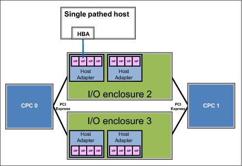
Figure 3-4 A single-path host connection
A more robust design is shown in Figure 3-5, in which the host is attached to separate Fibre Channel host adapters in separate I/O enclosures. This configuration is also important because during a LIC update, a host adapter port might need to be taken offline. This configuration allows host I/O to survive a hardware failure on any component on either path.

Figure 3-5 A dual-path host connection
SAN/FICON switches
Because many hosts can connect to the DS8880 each by using multiple paths, the number of host adapter ports that are available in the DS8880 might not be sufficient to accommodate all of the connections. The solution to this problem is the use of SAN switches or directors to switch logical connections from multiple hosts. In a z Systems environment, a SAN switch or director that supports Fibre Channel connection (FICON) is required.
A logic or power failure in a switch or director can interrupt communication between hosts and the DS8880. Provide more than one switch or director to ensure continued availability. Configure ports from two separate host adapters in two separate I/O enclosures to go through each of two directors. The complete failure of either director leaves the paths that are configured to the alternative director still available.
Using channel extension technology
For Copy Services scenarios in which single mode fiber distance limits are exceeded, use of channel extension technology is required. The following website contains information about network devices that are marketed by IBM and other companies to extend Fibre Channel communication distances. They can be used with DS8000 Series Metro Mirror, Global Copy, Global Mirror, Metro/Global Mirror (MGM) Support, and z/OS Global Mirror. For more information, see the DS8000 Series Copy Services Fibre Channel Extension Support Matrix:
Support for T10 Data Integrity Field standard
The DS8880 incorporates the ANSI T10 Data Integrity Field (DIF) standard for fixed-block (FB) volumes.
When data is read, the DIF is checked before the data leaves the DS8880 and again when the data is received by the host system. Previously, it was only possible to ensure the data integrity within the storage system with ECC. However, T10 DIF can now check end-to-end data integrity through the SAN. Checking is done by hardware, so no performance impact occurs.
For more information about T10 DIF implementation in the DS8880, see “T10 data integrity field support” on page 105.
Robust and resilient SAN data transfer
Forward Error Correction (FEC) is enabled on 16 Gbps host adapters by implementing redundant data transfer in terms of ECC. FEC is also implemented on z13 Systems to achieve the end-to-end prevention of I/O errors.
To provide more proactive system diagnosis information about SAN fabric systems, read diagnostic parameters, which comply to industry standards, are implemented on the DS8880. This function provides host software with the capability to perform predictive failure analysis on degraded SAN links before they fail.
Multipathing software
Each attached host operating system requires multipathing software to manage multiple paths to the same device, and to provide at least redundant routes for host I/O requests. When a failure occurs on one path to a logical device, the multipathing software on the attached host can identify the failed path and route the I/O requests for the logical device to alternative paths. Furthermore, it can likely detect when the path is restored. The multipathing software that is used varies by attached host operating system and environment, as described in the following sections.
Open systems
In most open systems environments, multipathing is available at the operating system level. The Subsystem Device Driver (SDD), which was provided and maintained by IBM for several operating systems, is the old approach for a multipathing solution.
For the AIX operating system, the DS8880 is supported through the AIX multipath I/O (MPIO) framework, which is included in the base AIX operating system. Choose either to use the base AIX MPIO support or to install the Subsystem Device Driver Path Control Module (SDDPCM).
For multipathing under Microsoft Windows, Subsystem Device Driver Device Specific Module (SDDDSM) is available.
For more information about the multipathing software that might be required for various operating systems, see the IBM System Storage Interoperation Center (SSIC) at this website:
Multipathing is covered in more detail in the IBM System Storage DS8000 Host Systems Attachment Guide, SC27-4210.
z Systems
In the z Systems environment, the preferred practice is to provide multiple paths from each host to a storage system. Typically, four or eight paths are installed. The channels in each host that can access each logical control unit (LCU) in the DS8880 are defined in the hardware configuration definition (HCD) or input/output configuration data set (IOCDS) for that host. Dynamic Path Selection (DPS) allows the channel subsystem to select any available (non-busy) path to start an operation to the disk subsystem. Dynamic Path Reconnect (DPR) allows the DS8880 to select any available path to a host to reconnect and resume a disconnected operation, for example, to transfer data after disconnection because of a cache miss.
These functions are part of the z Systems architecture and they are managed by the channel subsystem on the host and the DS8880.
A physical FICON path is established when the DS8880 port sees light on the fiber, for example, a cable is plugged in to a DS8880 host adapter, a processor or the DS8880 is powered on, or a path is configured online by z/OS. Now, logical paths are established through the port between the host, and part or all of the LCUs in the DS8880 are controlled by the HCD definition for that host. This configuration happens for each physical path between a z Systems host and the DS8880. Multiple system images can be in a CPU. Logical paths are established for each system image. The DS8880 then knows the paths that can be used to communicate between each LCU and each host.
Control-unit initiated reconfiguration (CUIR) varies off a path or paths to all z Systems hosts to allow service to an I/O enclosure or host adapter, then varies on the paths to all host systems when the host adapter ports are available. This function automates channel path management in z Systems environments in support of selected DS8880 service actions.
CUIR is available for the DS8880 when it operates in the z/OS and IBM z/VM® environments. CUIR provides automatic channel path vary on and vary off actions to minimize manual operator intervention during selected DS8880 service actions.
CUIR also allows the DS8880 to request that all attached system images set all paths that are required for a particular service action to the offline state. System images with the correct level of software support respond to such requests by varying off the affected paths, and either notifying the DS8880 subsystem that the paths are offline, or that it cannot take the paths offline. CUIR reduces manual operator intervention and the possibility of human error during maintenance actions, and reduces the time that is required for the maintenance. This function is useful in environments in which many z/OS or z/VM systems are attached to a DS8880.
3.3.3 Metadata checks
When application data enters the DS8880, special codes or metadata, which is also known as redundancy checks, are appended to that data. This metadata remains associated with the application data while it is transferred throughout the DS8880. The metadata is checked by various internal components to validate the integrity of the data as the data moves throughout the disk system. It is also checked by the DS8880 before the data is sent to the host in response to a read I/O request. The metadata also contains information that is used as an extra level of verification to confirm that the data that is returned to the host is coming from the location that you want on the disk.
The metadata check is independent of the DS8880 T10 DIF support for fixed-block volumes (Linux on z Systems and AIX on Power Systems). For more information about T10 DIF implementation in the DS8880, see “T10 data integrity field support” on page 105.
3.4 RAS on the Hardware Management Console
The Hardware Management Console (HMC) is used to configure, manage, and maintain the DS8880. One HMC (the primary) is included in every DS8880 base frame. A second HMC (the secondary) can be ordered, and is also in the base frame. The DS8880 HMCs work with IPv4, IPv6, or a combination of both IP standards. For more information about the HMC and network connections, see 8.1.1, “Management Console hardware” on page 203 and 7.3, “Network connectivity planning” on page 191.
The HMC is the DS8880 management focal point. If no HMC is operational, it is impossible to run maintenance, modifications to the logical configuration, or Copy Services tasks, such as the establishment of FlashCopies, by using the data storage command-line interface (DS CLI) or Storage Management GUI. Ordering and implementing a secondary HMC provides a redundant management focal point.
3.4.1 Licensed Internal Code updates
The DS8880 contains many discrete redundant components. The DS8880 architecture allows concurrent code updates. This ability is achieved by using the redundant design of the DS8880. The following components have firmware that can be updated concurrently:
•FSP
•DC-UPS
•Rack power control (RPC) cards
•Host adapters
•Fibre Channel interface cards (FCICs)
•Device adapters (DAs)
•Drives, flash drives, and flash cards
The DS8880 CPCs have an operating system (AIX) and licensed machine code (LMC) that can be updated. As IBM continues to develop and improve the DS8880, new releases of firmware and LMC become available that offer improvements in function and reliability. For more information about LIC updates, see Chapter 13, “Licensed machine code” on page 377.
3.4.2 Call home and remote support
This section describes the call home feature and remote support capability.
Call home
Call home is the capability of the DS8880 to notify the client and IBM Support to report a problem. Call home is configured in the HMC at installation time. Call home to IBM Support is done over the customer network through a secure protocol. Customer notification can also be configured as email or Simple Network Management Protocol (SNMP) alerts. An example of an email notification output is shown in Example 3-1.
Example 3-1 Typical email notification output
REPORTING SF MTMS: 2107-981*75DMC10
FAILING SF MTMS: 2107-981*75DMC10
REPORTING SF LPAR: SF75DMC10ESS11
PROBLEM NUMBER: 168
PROBLEM TIMESTAMP: Oct 30, 2015 2:52:22 AM MST
REFERENCE CODE: BE83CB93
************************* START OF NOTE LOG **************************
BASE RACK ORDERED MTMS 2834-981*75DMC10
LOCAL HMC MTMS 8100LI7*P210927 HMC ROLE Primary
LOCAL HMC INBOUND MODE Attended MODEM PHONE Unavailable
LOCAL HMC INBOUND CONFIG Continuous
LOCAL HMC OUTBOUND CONFIG None FTP: disabled
REMOTE HMC Single HMC
AOS STATUS Not Running AOS VERSION 4.0
AOS ACL=(DS8k, Storage) AOS TRACE Enable
HMC CE default HMC REMOTE default
HMC PE default HMC DEVELOPER default
2107 BUNDLE 88.0.135.0
HMC BUILD 20151021.1
LMC LEVEL v25.80.0 build level 20151025.2
FIRMWARE LEVEL SRV0 01SV810135 SRV1 01SV810135
PARTITION NAME SF75DMC10ESS11
PARTITION HOST NAME SF75DMC10ESS11
PARTITION STATUS SFI 2107-981*75DMC11 SVR 8286-42A*21C05AV LPAR SF75DMC10ESS11 STATE = AVAILABLE
FIRST REPORTED TIME Oct 30, 2015 2:52:22 AM MST
LAST REPORTED TIME Oct 30, 2015 2:52:22 AM MST
CALL HOME RETRY #0 of 12 on Oct 30, 2015 2:52:22 AM MST.
REFCODE BE83CB93..... <=== System Reference Code (SRC)
SERVICEABLE EVENT TEXT
Device adapter reset reached threshold, adapter fenced. ... <=== Description of Problem
FRU group MEDIUM FRU class FRU
FRU Part Number 31P1452 FRU CCIN DAD4
FRU Serial Number YP10BG37K005
FRU Location Code U1500.1B2.RJBAY02-P1-C6
FRU Previously Replaced No
FRU Previous PMH N/A
************************** END OF NOTE LOG ***************************
For more information about planning the connections that are needed for HMC installations, see Chapter 8, “IBM DS8880 Management Console planning and setup” on page 201.
For more information about setting up SNMP notification, see Chapter 14, “Monitoring with Simple Network Management Protocol” on page 387.
Remote support
Remote Support is the ability of an IBM support representative to remotely access the DS8880. This capability can be configured at the HMC, and access is by Assist On-site (AOS).
For more information about remote support operations, see Chapter 15, “Remote support” on page 401.
For more information about AOS, see IBM Assist On-site for Storage Overview, REDP-4889.
3.5 RAS on the storage subsystem
The DS8880 was designed to safely store and retrieve large amounts of data. Redundant Array of Independent Disks (RAID) is an industry-wide method to store data on multiple physical disks to enhance data redundancy. Many variants of RAID are in use today. The DS8880 supports RAID 5, RAID 6, and RAID 10. The DS8880 does not support a non-RAID configuration of disks, which is also known as just a bunch of disks (JBOD).
3.5.1 RAID configurations
The following RAID configurations are supported on DS8880:
•6+P RAID 5 configuration: The array consists of six data drives and one parity drive. This configuration is used in high-performance flash enclosure (HPFE) arrays.
•6+P+S RAID 5 configuration: The array consists of six data drives and one parity drive. The remaining drive of the array site is used as a spare.
•7+P RAID 5 configuration: The array consists of seven data drives and one parity drive.
•5+P+Q+S RAID 6 configuration: The array consists of five data drives and two parity drives. The remaining drive on the array site is used as a spare.
•6+P+Q RAID 6 configuration: The array consists of six data drives and two parity drives.
•3+3+2S RAID 10 configuration: The array consists of three data drives that are mirrored to three copy drives. Two drives on the array site are used as spares.
•4+4 RAID 10 configuration: The array consists of four data drives that are mirrored to four copy drives.
|
Note: The following characteristics refer to RAID:
•Spare drives are globally available to the DA pair.
•The +P/+Q indicators do not mean that a single drive is dedicated to holding the parity bits for the RAID. The DS8880 uses floating parity technology so that no single drive is always involved in every write operation. The data and parity stripes float among the member drives of the array to provide optimum write performance.
|
For more information about the effective capacity of these configurations, see Table 7-9 on page 197.
Capacity Magic is an easy-to-use tool to help with capacity planning for physical and usable capacities based on installation drive capacities and quantities in intended RAID configurations.
If RAID reconfiguration is required, an available capacity of free space is required, and it must be allowed for. For example, if the storage system is 99% provisioned with RAID-6 arrays, it might not be possible to complete an online reconfiguration to reconfigure a RAID 6 array into a RAID 5 array.
|
Important restrictions: The following restrictions apply:
•Nearline drives are supported in RAID 6 configurations.
•Flash drives are supported in RAID 5 configurations only.
This information is subject to change. Consult with the IBM SSR for the latest information about supported RAID configurations.
The request for price quotation (RPQ)/Storage Customer Opportunity REquest (SCORE) System process can be used to submit requests for other RAID configurations for solid-state flash drives and nearline drives.
|
3.5.2 Drive path redundancy
Each drive in the DS8880 is attached to two Fibre Channel switches. These switches are built into the standard drive enclosure FCICs. Figure 3-6 shows the redundancy features of the DS8880 switched Fibre Channel Arbitrated Loop (FC-AL) drive architecture.
Each drive has two separate connections to the enclosure backplane. This configuration allows a drive to be simultaneously attached to both FC switches. If either drive enclosure FCIC is removed from the enclosure, the switch that is included in that FCIC is also removed. However, the FC switch in the remaining FCIC retains the ability to communicate with all the drives and both DAs in a pair. Similarly, each DA has a path to each switch, so it can also tolerate the loss of a single path. If both paths from one DA fail, it cannot access the switches. However, the partner DA retains connection.

Figure 3-6 Standard drive enclosure - switched FC-AL paths
Figure 3-6 also shows the connection paths to the neighboring drive enclosures. Because expansion is performed in this linear fashion, adding enclosures is nondisruptive.
For more information about the drive subsystem of the DS8880, see 2.5, “Storage enclosures and drives” on page 46.
3.5.3 Predictive Failure Analysis
The storage drives that are used in the DS8880 incorporate Predictive Failure Analysis (PFA) and can anticipate certain forms of failures by keeping internal statistics of read and write errors. If the error rates exceed predetermined threshold values, the drive is nominated for replacement. Because the drive did not yet fail, data can be copied directly to a spare drive by using the technique that is described in 3.5.5, “Smart Rebuild” on page 80. This copy ability avoids the use of RAID recovery to reconstruct all of the data onto the spare drive.
3.5.4 Disk scrubbing
The DS8880 periodically reads all sectors on a disk. This reading is designed to occur without any interference with application performance. If ECC detects correctable bad bits, the bits are corrected immediately. This ability reduces the possibility of multiple bad bits accumulating in a sector beyond the ability of ECC to correct them. If a sector contains data that is beyond ECC’s ability to correct, RAID is used to regenerate the data and write a new copy onto a spare sector of the drive. This scrubbing process applies to drives that are array members and spares.
3.5.5 Smart Rebuild
Smart Rebuild is a function that is designed to help reduce the possibility of secondary failures and data loss of RAID arrays. It can be used to rebuild a RAID 5 array when certain drive errors occur and a normal determination is made that it is time to use a spare to proactively replace a failing drive. If the suspect drive is still available for I/O, it is kept in the array rather than being rejected as under a standard RAID rebuild. A spare is brought into the array at the same time.
The suspect drive and the new spare are set up in a temporary RAID 1 association, allowing the troubled drive to be duplicated onto the spare rather than running a full RAID reconstruction from data and parity. The new spare is then made a regular member of the array and the suspect drive is rejected from the RAID array. The array never goes through an n-1 stage in which it might suffer a complete failure if another drive in this array encounters errors. The result saves substantial time and provides a new level of availability that is not in other RAID 5 products.
Smart Rebuild is not applicable in all situations, so it is not always used. If two drives with errors are in a RAID 6 configuration, or if the drive mechanism failed to the point that it cannot accept any I/O, the standard RAID rebuild procedure is used for the RAID array. If communications across a drive fabric are compromised, such as an FC-AL loop error that causes the drive to be bypassed, standard RAID rebuild procedures are used because the suspect drive is not available for a one-to-one copy with a spare. If Smart Rebuild is not possible or does not provide the designed benefits, a standard RAID rebuild occurs.
Smart Rebuild drive error patterns are continuously analyzed as part of one of the normal tasks that are run by the DS8880 LIC. Drive firmware is optimized to report predictive errors to the DA. At any time, when certain drive errors (following specific criteria) reach a determined threshold, the RAS LIC component starts Smart Rebuild within the hour. This enhanced technique, when it is combined with a more frequent schedule, leads to considerably faster identification if drives show signs of imminent failure.
A fast response in fixing drive errors is vital to avoid a second drive failure in the same RAID 5 array, and to avoid potential data loss. The possibility of having an array that has no redundancy, such as when a RAID rebuild occurs, is reduced by shortening the time when a specific error threshold is reached until Smart Rebuild is triggered, as described in the following scenarios:
•Smart Rebuild might avoid the circumstance in which a suspected drive is rejected because Smart Rebuild process is started before rejection. Therefore, Smart Rebuild prevents the array from going to a standard RAID rebuild, during which the array has no redundancy and is susceptible to experiencing a second drive failure.
•Crossing the drive error threshold is detected by DS8880 LIC immediately because DS8880 LIC continuously analyzes drive errors.
•RAS LIC component starts Smart Rebuild after Smart Rebuild threshold criteria are met. The Smart Rebuild process runs every hour and does not wait for 24 hours as in the past.
IBM remote support representatives can manually start a Smart Rebuild if needed, such as when two drives in the same array logged temporary media errors. In this case, it is considered appropriate to manually start the rebuild.
3.5.6 RAID 5 overview
The DS8880 supports RAID 5 arrays. RAID 5 is a method of spreading volume data plus parity data across multiple drives. RAID 5 provides faster performance by striping data across a defined set of drives. Data protection is provided by the generation of parity information for every stripe of data. If an array member fails, its contents can be regenerated by using the parity data.
The DS8880 uses the idea of striped parity, which means that no single drive in an array is dedicated to holding parity data, which makes such a drive active in every I/O operation. Instead, the drives in an array rotate between holding data stripes and holding parity stripes, balancing out the activity level of all drives in the array.
RAID 5 implementation in DS8880
In DS8880 standard drive enclosures, an array that is built on one array site contains eight disks. The first four array sites on a DA pair have a spare assigned, and the rest of the array sites have no spare assigned, if all disks are the same capacity and speed. An array site with a spare creates a RAID 5 array that is 6+P+S (where the P stands for parity and S stands for spare). The other array sites on the DA pair are 7+P arrays.
HPFEs contain a total of four array sites only. The first two array sites contain eight flash cards each, which form 6+P+S arrays. The next two array sites contain seven flash cards each, which form 6+P arrays. The HPFE contains only two spare flash cards.
Drive failure with RAID 5
When a drive fails in a RAID 5 array, the device adapter rejects the failing drive and takes one of the hot spare drives. Then the DA starts the rebuild, which is an operation to reconstruct the data that was on the failed drive onto one of the spare drives. The spare that is used is chosen based on a smart algorithm that looks at the location of the spares and the size and location of the failed drive. The RAID rebuild is run by reading the corresponding data and parity in each stripe from the remaining drives in the array, running an exclusive-OR operation to re-create the data, and then writing this data to the spare drive.
While this data reconstruction occurs, the device adapter can still service read and write requests to the array from the hosts. Performance might degrade while the rebuild operation is in progress because DA and switched network resources are used to complete the reconstruction. Because of the switch-based architecture, this effect is minimal. Also, any read requests for data on the failed drive require data to be read from the other drives in the array, and then the DA reconstructs the data.
Performance of the RAID 5 array returns to normal when the data reconstruction onto the spare drive completes. The time that is required for rebuild varies depending on the capacity of the failed drive and the workload on the array, the switched network, and the DA. The use of array across loops (AAL) speeds up rebuild time and decreases the impact of a rebuild.
HPFEs do not have AAL because the enclosure is not part of a pair.
3.5.7 RAID 6 overview
The DS8880 supports RAID 6 protection. RAID 6 presents an efficient method of data protection in double drive errors, such as two drive failures, two coincident medium errors, or a drive failure and a medium error. RAID 6 protection provides more fault tolerance than RAID 5 in drive failures and uses less raw drive capacity than RAID 10.
RAID 6 allows more fault tolerance by using a second independent distributed parity scheme (dual parity). Data is striped on a block level across a set of drives, similar to RAID 5 configurations. The second set of parity is calculated and written across all of the drives and reduces the usable space compared to RAID 5. The striping is shown in Figure 3-7.
RAID 6 is best used with large-capacity drives because they have a longer rebuild time. One risk is that longer rebuild times increase the possibility that a second drive error occurs during the rebuild window. Comparing RAID 6 to RAID 5 performance gives about the same results on reads. For random writes, the throughput of a RAID 6 array is only two-thirds of a RAID 5, due to the additional parity handling. Workload planning is important before RAID 6 for write-intensive applications is implemented, including Copy Services targets.
When RAID 6 is sized correctly for the I/O demand, it is a considerable reliability enhancement, as shown in Figure 3-7.

Figure 3-7 Illustration of one RAID 6 stripe on a 5+P+Q+S array
RAID 6 implementation in the DS8880
A RAID 6 array in one array site of a DS8880 can be built on one of the following configurations:
•In a seven-drive array, two drives are always used for parity, and the eighth drive of the array site is needed as a spare. This type of RAID 6 array is referred to as a 5+P+Q+S array, where P and Q stand for parity and S stands for spare.
•A RAID 6 array, which consists of eight drives, is built when all necessary spare drives are configured for the DA pair. An eight-drive RAID 6 array also always uses two drives for parity, so it is referred to as a 6+P+Q array.
Drive failure with RAID 6
When a drive fails in a RAID 6 array, the DA starts to reconstruct the data of the failing drive onto one of the available spare drives. A smart algorithm determines the location of the spare drive to use, depending on the capacity and the location of the failed drive. After the spare drive replaces a failed drive in a redundant array, the recalculation of the entire contents of the new drive is run by reading the corresponding data and parity in each stripe from the remaining drives in the array. This data is then written to the spare drive.
During the rebuild of the data on the new drive, the DA can still handle I/O requests of the connected hosts to the affected array. Performance degradation might occur during the reconstruction because DAs and switched network resources are used to do the rebuild. Because of the switch-based architecture of the DS8880, this effect is minimal. Additionally, any read requests for data on the failed drive require data to be read from the other drives in the array, and then the DA reconstructs the data. Any subsequent failure during the reconstruction within the same array (second drive failure, second coincident medium errors, or a drive failure and a medium error) can be recovered without data loss.
Performance of the RAID 6 array returns to normal when the data reconstruction on the spare drive is complete. The rebuild time varies, depending on the capacity of the failed drive and the workload on the array and the DA. The completion time is comparable to a RAID 5 rebuild, but slower than rebuilding a RAID 10 array in a single drive failure.
|
Note: HPFEs do not support RAID 6.
|
3.5.8 RAID 10 overview
RAID 10 provides high availability by combining features of RAID 0 and RAID 1. RAID 0 optimizes performance by striping volume data across multiple drives. RAID 1 provides drive mirroring, which duplicates data between two drives. By combining the features of RAID 0 and RAID 1, RAID 10 provides a second optimization for fault tolerance. Data is striped across half of the drives in the RAID 1 array. The same data is also striped across the other half of the array, which creates a mirror. Access to data is preserved if one drive in each mirrored pair remains available. RAID 10 offers faster data reads and writes than RAID 5 because it does not need to manage parity. However, with half of the drives in the group used for data and the other half mirroring that data, RAID 10 arrays have less usable capacity than RAID 5 or RAID 6 arrays.
RAID 10 is commonly used for workloads that require the highest performance from the drive subsystem. Typical areas of operation for RAID 10 are workloads with a high random write ratio. Either member in the mirrored pair can respond to the read requests.
RAID 10 implementation in DS8880
In the DS8880, the RAID 10 implementation is achieved by using six or eight drives. If spares need to be allocated from the array site, six drives are used to make a three-drive RAID 0 array, which is then mirrored to a three-drive array (3x3). If spares do not need to be allocated, eight drives are used to make a four-drive RAID 0 array, which is then mirrored to a four-drive array (4x4).
Drive failure with RAID 10
When a drive fails in a RAID 10 array, the DA rejects the failing drive and takes a hot spare into the array synthesists. Data is then copied from the good drive to the hot spare drive. The spare that is used is chosen based on a smart algorithm that looks at the location of the spares and the size and location of the failed drive. Remember, a RAID 10 array is effectively a RAID 0 array that is mirrored. Therefore, when a drive fails in one of the RAID 0 arrays, you can rebuild the failed drive by reading the data from the equivalent drive in the other RAID 0 array.
While this data copy is occurring, the DA can still service read and write requests to the array from the hosts. Performance might degrade while the copy operation is in progress because DA and switched network resources are used to rebuild the RAID. Because a good drive is available, this effect is minimal. Read requests for data on the failed drive likely are not affected because they are all directed to the good copy on the mirrored drive. Write operations are not affected.
Performance of the RAID 10 array returns to normal when the data copy onto the spare drive completes. The time that is taken for rebuild can vary, depending on the capacity of the failed drive and the workload on the array and the DA. In relation to a RAID 5, RAID 10 rebuild completion time is faster because rebuilding a RAID 5 6+P configuration requires six reads plus one parity operation for each write. However, a RAID 10 configuration requires one read and one write (essentially, a direct copy).
Array across loops and RAID 10
The DS8880, as with previous generations, implements the concept of AAL. With AAL, an array site is split into two halves. Half of the site is on the first drive loop of a DA pair and the other half is on the second drive loop of that DA pair. AAL is implemented primarily to maximize performance, and is used for all the RAID types in the DS8880. However, with RAID 10, you can take advantage of AAL to provide a higher level of redundancy. The DS8880 RAS code deliberately ensures that one RAID 0 array is maintained on each of the two loops that are created by a DA pair. This configuration means that in the unlikely event of a complete loop outage, the DS8880 does not lose access to the RAID 10 array. This access is not lost because when one RAID 0 array is offline, the other remains available to service drive I/O. Figure 2-24 on page 52 shows a diagram of this strategy.
3.5.9 Spare creation
This section describes methods of spare creation.
Standard drive enclosures
When the arrays are created on a DS8880 standard drive enclosure, the LIC determines the array sites that contain spares. The first array sites on each DA pair that are assigned to arrays contribute one or two spares (depending on the RAID option) until the DA pair has access to at least four spares, with two spares placed on each loop.
A minimum of one spare is created for each array site that is assigned to an array until the following conditions are met:
•A minimum of four spares per DA pair exist.
•A minimum of four spares for the largest capacity array site on the DA pair exist.
•A minimum of two spares of capacity and revolutions per minute (RPM) greater than or equal to the fastest array site of any capacity on the DA pair exist.
High-performance flash enclosures
The HPFE is a single enclosure that is a DA pair. HPFEs contain a total of four array sites only. The first two array sites contain eight flash cards each to form a 6+P+S array. The next two array sites contain seven flash cards each to form 6+P arrays. The HPFE always contains only two spare flash cards.
Spare rebalancing
The DS8880 implements a spare rebalancing technique for spare drives. When a drive fails and a hot spare is taken, it becomes a member of that array. When the failed drive is repaired, DS8880 LIC might choose to allow the hot spare to remain where it was moved. However, it can instead choose to migrate the spare to a more optimum position. This migration is performed to better balance the spares across the FC-AL loops to provide the optimum spare location based on drive capacity and spare availability.
It might be preferable that the drive that is in use as an array member is converted to a spare. In this case, the data on that disk drive module (DDM) is migrated in the background onto an existing spare by using the Smart Rebuild technique. For more information, see 3.5.5, “Smart Rebuild” on page 80. This process does not fail the disk that is being migrated. However, the process reduces the number of available spares in the DS8880 until the migration process is complete.
In a drive intermix on a DA pair, it is possible to rebuild the contents of a 300 GB drive onto a 600 GB spare drive. However, approximately one-half of the 600 GB drive is wasted because that space cannot be used. When the failed 300 GB drive is replaced with a new 300 GB drive, the DS8880 LIC migrates the data back onto the recently replaced 300 GB drive. When this process completes, the 300 GB DDM rejoins the array and the 600 GB drive becomes the spare again. This same algorithm applies when the hot spare that is taken at the time of the initial drive failure has a speed mismatch.
HPFE does not need to rebalance the spare.
Hot pluggable drives
Replacement of a failed drive does not affect the operation of the DS8880 because the drives are fully hot pluggable. Each drive plugs into a switch, so no loop break is associated with the removal or replacement of a drive. In addition, no potentially disruptive loop initialization process occurs.
Enhanced sparing
The drive sparing policies support having spares for all capacity and speed drives on the DA pair. When any DA pair has only a single spare for any drive type, a call home to IBM is generated. Because of spare over-allocation, several drives can be in a Failed/Deferred Service state. All failed drives are included in the call home when any drive type has one spare. For example, in a configuration with 16 flash drives on a DA pair, two spares are created. If one flash drive fails, all failed drives in the storage system of any type are reported to IBM.
The following DS CLI command can be used to know whether actions can be deferred:
lsddm -state not_normal IBM.2107-75XXXXX
An example of where repair can be deferred is shown in Example 3-2.
Example 3-2 DS CLI lsddm command shows DDM state
dscli> lsddm -state not_normal IBM.2107-75DMC71
Date/Time: November 18, 2015 5:11:14 PM MST IBM DSCLI Version: 7.8.0.414 DS: IBM.2107-75DMC71
ID DA Pair dkcap (10^9B) dkuse arsite State
==============================================================================================
IBM.2107-D02-06MZ7/R1-P1-D24 0 146.0 unconfigured S1 Failed/Deferred Service
If immediate repair for drives in the Failed/Deferred Service state is needed, an RPQ/SCORE process can be used to submit a request to disable enhanced sparing service. For more information, contact your marketing representative for the details of this RPQ.
3.6 RAS on the power subsystem
All power and cooling components that constitute the DS8880 power subsystem are fully redundant. Key elements that allow this high level of redundancy are two DC-UPSs for each frame for a 2N redundancy. By using this configuration, DC-UPSs are duplicated in each frame so that only one DC-UPS by itself provides enough power for all components inside a frame, if the other DC-UPS becomes unavailable.
As described in “Battery service module sets” on page 87, each DC-UPS has its own battery backup function. Therefore, the battery system in DS8880 also has 2N redundancy. The battery of a single DC-UPS allows the completion of the FHD if a dual AC loss occurs (as described in 3.2.4, “NVS and power outages” on page 70).
The CPCs, I/O enclosures, drive enclosures, and primary HMC components in the frame all feature duplicated power supplies.
Smart internal power distribution connectivity makes it possible to maintain redundant power distribution on a single power cord. If one DC-UPS power cord is pulled (equivalent to a failure in one of the client circuit breakers), the partner DC-UPS can provide power to this UPS and feed each internal redundant power supply inside the frame. For example, if a DC-UPS power cord is pulled, the two redundant power supplies of any CPC continue to be powered on. This ability gives an extra level of reliability in the unusual case of failure in multiple power elements.
In addition, internal Ethernet switches and tray fans, which are used to provide extra cooling to the internal HMC, receive redundant power.
3.6.1 Power components
This section describes the power subsystem components of the DS8880 from an RAS standpoint.
Direct current uninterruptible power supply
Two DC-UPS units exist for each frame for a 2N redundancy. The DC-UPS is a built-in power converter that can monitor power and integrated battery functions. It distributes full wave rectified AC to Power Distribution Units (PDUs), which then provide that power to all areas of the system.
If AC is not present at the input line, the output is switched to rectified AC from the partner DC-UPS. If neither AC input is active, the DC-UPS switches to battery power for up to 4 seconds, or 40 seconds if the ePLD feature is installed. Each DC-UPS has internal fans to supply cooling for that power supply. If AC input power is not restored before the ride through time expires, an emergency shutdown results, and FHD copies the data in NVS to the CPC hard disk drives to prevent data loss.
DC-UPS supports high or low voltage single-phase and three-phase as input power. The correct power cables and power select jumper must be used. For information about power cord feature codes, see the IBM DS8880 Introduction and Planning Guide, GC27-8525.
All elements of the DC-UPS can be replaced concurrently with client operations. Furthermore, BSM set replacement and DC-UPS fan assembly are performed while the corresponding direct current supply unit remains operational.
The following important enhancements also are available:
•DC-UPS data collection is improved.
•During DC-UPS firmware update, the current power state is maintained so that the DC-UPS remains operational during this service operation. Because of its dual firmware image design, dual power redundancy is maintained in all internal power supplies of all frames during the DC-UPS firmware update.
Each DC-UPS unit consists of one direct current supply unit (DSU) and one BSM set. Figure 2-26 on page 57 shows the DSU (rear view) and BSMs (front view).
|
Important: If a DS8880 is installed so that both DC-UPSs are attached to the same circuit breaker or the same power distribution unit, the DS8880 is not well-protected from external power failures. This configuration can cause an unplanned outage.
|
Direct current supply unit
Each DC-UPS has a direct current supply unit (DSU), which contains the control logic of the DC-UPS and it is where images of the power firmware are located. It is designed to protect the DSU from failures during a power firmware update, avoiding physical intervention or hardware replacement, except in a permanent hardware failure.
A DSU contains the necessary battery chargers that are dedicated to monitor and charge the BSM set that is installed in the DC-UPS.
Battery service module sets
The BSM set provides backup power to the system when both AC inputs to a frame are lost. Each DC-UPS supports one BSM set. If the ePLD feature is ordered, no additional BSM set is installed. For more information, see 3.6.3, “Line power fluctuation” on page 89.
A BSM set consists of four battery enclosures. Each of these single-battery enclosures is known as a BSM. A group of four BSMs (battery enclosures) makes up a BSM set. Two types of BSMs are available: The primary BSM and the secondary BSM. The primary BSM is the only BSM with an electrical connector to the DSU and it can be installed only in the top location. This primary BSM is the only BSM that has status LEDs. Three secondary BSMs exist.
The DS8880 BSMs have a fixed working life of five years. The fixed working life is four years if the ePLD feature is installed.
Power Distribution Unit
The PDUs are used to distribute power from the DC-UPS through the power distribution units to the power supplies in drive enclosures, CPCs, I/O enclosures, Ethernet switches, and HMC fans.
Four PDUs are in all frames. A PDU module can be replaced concurrently.
Drive enclosure power supplies
The drive enclosure power supply units provide power for the drives, and they house the cooling fans for the drive enclosure. The fans draw air from the front of the frame, through the drives, and then move it out through the back of the frame. The entire frame cools from front to back, complying with the data center hot aisle/cold aisle cooling strategy. Redundant fans are in each power supply unit, and redundant power supply units are in each drive enclosure. The drive enclosure power supply can be replaced concurrently. Figure 2-21 on page 49 shows a front and rear view of a disk enclosure.
The PDUs for drive enclosures can supply power for 5 - 7 drive enclosures. Each drive enclosure power supply plugs into two separate PDUs, which are supplied from separate DC-UPSs.
CPC power supplies and I/O enclosure power supplies
Each CPC and I/O enclosure has dual redundant power supplies to convert power that is provided by PDUs into the required voltages for that enclosure or complex. Each I/O enclosure and each CPC has its own cooling fans.
Power junction assembly
The power junction assembly (PJA) provides redundant power to HMCs and Ethernet switches.
Rack power control card
RPC cards manage the DS8880 power subsystem and provide control, monitoring, and reporting functions. RPC cards are responsible for receiving DC-UPS status and controlling DC-UPS functions. Two RPC cards are included for redundancy. When one RPC card is unavailable, the remaining RPC card performs all RPC functions.
The following RPC enhancements are available in DS8880 (compared to previous generations of DS8000):
•The DS8880 RPC card contains a faster processor and more parity-protected memory.
•Two different buses are for communication between each RPC card and each CPC. These buses provide redundant paths to have an error recovery capability in a failure of one of the communication paths.
•Each RPC card has two firmware images. If an RPC firmware update fails, the RPC card can still boot from the other firmware image. This design also leads to a reduced period during which one of the RPC cards is unavailable because of an RPC firmware update. Because of the dual firmware image, an RPC card is only unavailable for the time that is required (only a few seconds) to boot from the new firmware image after it is downloaded. Because of this configuration, full RPC redundancy is available during most of the time that is required for an RPC firmware update.
•The RPC cards control power to the attached I/O enclosures. They also monitor environmental components such as power, fans, and temperature for the I/O enclosures. Environmental critical and noncritical conditions can generate EPOW events. Critical events trigger the correct signals from the hardware to the affected components to prevent any data loss without operating system or firmware involvement. Non-critical environmental events are also logged and reported.
3.6.2 Line power loss
The DS8880 uses an area of server memory as NVS. This area of memory is used to hold modified data that is not yet written to the storage drives. If line power fails, meaning that both DC-UPSs in a frame report a loss of AC input power, the DS8880 must protect that data. For a full explanation of the NVS and cache operation, see 3.2, “CPC failover and failback” on page 67.
3.6.3 Line power fluctuation
The DS8880 frames contain BSM sets that protect modified data if dual AC power is lost to the entire frame. If a power fluctuation occurs that causes a momentary interruption to power (often called a brownout), the DS8880 tolerates this condition for approximately 4 seconds. If the ePLD feature is not installed on the DS8880 system, the drives are powered off and the servers begin copying the contents of NVS to the internal disks in the CPCs. For many clients who use uninterruptible power supply (UPS) technology, brownouts are not an issue. UPS-regulated power is reliable, so more redundancy in the attached devices is often unnecessary.
Extended power line disturbance
If power at the installation is not always reliable, consider adding the ePLD feature.
Without the ePLD feature, a standard DS8880 offers protection of about 4 seconds from power line disturbances. Installing this feature increases the protection to 40 seconds (running on battery power for 40 seconds) before an FHD begins. For a full explanation of this process, see 3.2.4, “NVS and power outages” on page 70.
3.6.4 Power control
Power control is modified through the HMC, which communicates sequencing information to the service processor in each CPC and RPC. Power control of the DS8880 can be performed by using the Service Maintenance Console Web User Interface (WUI) or by using the DS8880 Storage Management GUI or DS CLI commands.
Figure 3-8 on page 90 shows the power control window of the Storage Management GUI.
In addition, the following switches in the base frame of a DS8880 are accessible when the rear cover is open:
•Local/remote switch. This switch has two positions: Local and remote.
•Local power on/local force power off switch. When the local/remote switch is in local mode, the local power on/local force power off switch can manually power on or force power off to a complete system. When the local/remote switch is in remote mode, the HMC is in control of power on/power off.
|
Important: The Local/remote switch must not be used by DS8880 users. The switch can be used only under certain circumstances and as part of an action plan that is performed by an IBM SSR.
|

Figure 3-8 DS8880 Modify power control from the Storage Management GUI
3.7 Other features
Many more features of the DS8880 enhance reliability, availability, and serviceability. Several of these features are described in this section.
3.7.1 Internal network
Each DS8880 base frame contains 2-Gigabit Ethernet switches to allow the creation of a fully redundant private management network. Each CPC in the DS8880 has a connection to each switch. The primary HMC (and the secondary HMC, if installed) has a connection to each switch. This configuration means that if a single Ethernet switch fails, all communication can complete from the HMCs to other components in the storage system that are using the alternative private network.
|
Note: The Ethernet switches are for use that is internal to DS8880 private networks. No external connection to the private networks is allowed. Client connectivity to the DS8880 is allowed only through the provided external Ethernet connector at the rear of the base frame.
|
3.7.2 Earthquake resistance
The Earthquake Resistance Kit is an optional seismic kit for stabilizing the storage system frame so that the frame complies with IBM earthquake resistance standards. It helps to prevent personal injury and increases the probability that the system will be available following an earthquake by limiting potential damage to critical system components.
Storage system frames with this optional seismic kit include hardware at the bottom of the frame that secures it to the floor. Depending on the flooring in your environment (specifically, non-raised floors), installation of the required floor mounting hardware might be disruptive. This kit must be special-ordered for the DS8880. For more information, contact your IBM sales representative.
3.7.3 Secure Data Overwrite
Secure Data Overwrite (SDO) is a process that provides a secure overwrite of all data drives in a DS8880 series storage system. Removal of all logical configuration and encryption groups are a required client activity before SDO can be run. The SDO process is started by the IBM SSR. The process continues unattended until it is complete. This process takes a full day to complete. Two DDM overwrite options are available.
Drive overwrite options
Two options are available for SDO. This section describes both options. Both options comply with National Institute of Standards and Technology (NIST) Special Publication 800-88r1.
Three-pass overwrite
This option runs a cryptoerase on the drives, then runs a three-pass overwrite on all drives.
Cryptoerase
This option runs a cryptoerase on the drives, which obfuscates the internal encryption key on the drives, rendering the previous information unreadable. It then runs a single-pass overwrite on all drives. Compared to the three-pass overwrite SDO, this option reduces the overall duration of the SDO process.
CPC and HMC
With either option, a three-pass overwrite is run on areas of both the CPC and HMC disk drives that contain any client-related information. If a secondary HMC is associated with the storage system, SDO runs against the secondary HMC after completion on the primary HMC. This SDO detects the previous SDO and runs an overwrite only on the secondary HMC hard disks.
SDO process overview
The basic steps in the SDO process are listed:
1. Client removal of all logical configuration and encryption groups.
2. IBM SSR starts SDO on the HMC.
3. SDO runs a dual cluster restart of the CPCs.
4. SDO cryptoerases all drives in the storage system.
5. SDO starts an overwrite method.
6. SDO starts a three-pass overwrite on the CPC and HMC hard disks.
7. When complete, SDO generates a certificate.
Certificate
The certificate can be offloaded by using DS CLI. If this offload is not possible, the IBM SSR can offload the certificate to removable media.
..................Content has been hidden....................
You can't read the all page of ebook, please click here login for view all page.