


IBM DS8880 hardware components and architecture
This chapter describes the hardware components of the IBM DS8880. It provides insights into the architecture and individual components.
This chapter covers the following topics:
2.1 Terminology of the DS8880
It is important to understand the naming conventions that are used to describe the DS8880 components and features. Although most terms are introduced in other chapters of this book, they are repeated and summarized here.
2.1.1 Storage system
The term storage system describes a single DS8880 (base frame plus other installed expansion frames).
Base frame
The DS8880 has three available base frame models. DS8888 (Model 982), DS8886 (Model 981), and DS8884 (Model 980). Each is a complete storage system that can be contained within a single base frame. To increase the storage capacity, expansion frames can be added. Each base frame is equipped with a Hardware Management Console (HMC). The base frame can also contain an optional second HMC.
For more information about the base frame configuration, see 2.2.4, “DS8880 base frames (models 982, 981, and 980)” on page 29.
Expansion frame
The 98F (DS8888), 98E (DS8886) and 98B (DS8884) model types are used for expansion frames in the DS8880.
A single expansion frame can be added to the DS8888 configuration. Up to four expansion frames can be added to the DS8886 configuration, and up to two expansion frames can be added to the DS8884 configuration.
To add an expansion frame to a DS8888, the system must first be configured with 2048 GB of total system memory. This configuration includes two additional 12-core processors per server, for a total of 48 cores per server.
To add expansion frames to a DS8886 system, the system must first be configured with a minimum of 512 GB of total system memory and dual 8-core processors per server. For a DS8884 system, the minimum total system memory that is required to add expansion frames is 128 GB.
All DS8880 system memory and processor upgrades can be performed concurrently.
Expansion frames of previous generation DS8000 storage systems are not supported and cannot be installed in a DS8880 storage system.
For more information about the expansion frame configuration, see 2.2.5, “DS8880 expansion frames (models 98F, 98E, and 98B)” on page 31.
2.1.2 Management Console
The Management Console, which is also known as the HMC, is the focal point for management operations of the DS8880. The HMC provides connectivity to the client’s network, and communications to the system private networks, power subsystem, and other management systems. All storage configuration, user-controlled tasks, and service actions are managed through the HMC. Although many other IBM products use an HMC, the installed Licensed Internal Code (LIC) makes the DS8880 HMC unique to these systems.
2.1.3 Central processor complex
The DS8880 has two POWER8 servers, which are referred to as central processor complexes (CPCs). The CPC is also known as the processor complex or the internal server. The CPCs for each model type have these characteristics:
•Each DS8888 CPC can have either 24 or 48 processor cores, and either 512 GB or 1024 GB of processor memory, for 1024 GB or 2048 GB of total system memory.
•Each DS8886 CPC can have 8 - 24 processor cores, and 64 - 1,024 GB of processor memory, for 128 GB - 2048 GB of total system memory.
•Each DS8884 CPC has six processor cores and can have 32 - 128 Gb of processor memory, for 64 GB - 256 GB of total system memory.
Both CPCs in a DS8880 system share the system workload. The CPCs are redundant, and either CPC can fail over to the other CPC if failure or planned downtime occurs. The CPCs are identified as CPC 0 and CPC 1.
One logical partition in each CPC runs the AIX V7.x operating system and storage-specific LIC. This logical partition is called the storage node. The storage servers are identified as Node 0 and Node 1.
Similar to earlier generations of the IBM DS8000 series, the DS8880 consists of one base frame, which incorporates the processor complexes, and optional expansion frames that mainly serve to host more drives. The CPCs in the base frame can be upgraded with more processor cores and system memory to accommodate growing performance, or when more storage capacity or host connectivity is required.
Upgrades from the smallest to the largest configuration in terms of system memory, processors, storage capacity, and host attachment can be performed concurrently. These scalability and upgrade characteristics make the DS8880 the most suitable system for large consolidation projects.
|
Note: The DS8884, DS8886, and DS8888 hardware platforms are specific to each configuration. Upgrades are not supported from one hardware platform to another.
|
2.2 DS8880 configurations and models
This section presents the current DS8880 configurations and models. The DS8880 storage systems are associated with machine type 283x. This machine type corresponds to the length of warranty offer that allows a one-year, two-year, three-year, or four-year warranty period (where x equals the number of years). Expansion frames have the same 283x machine type as the base rack.
The DS8880 is designed for modular expansion. From a high-level view, IBM offers three configurations of the DS8880:
•DS8888 configuration
•DS8886 configuration
•DS8884 configuration
However, the physical racks themselves are almost identical. The main variations are the combinations of CPCs, I/O enclosures, storage enclosures, disks, and direct current uninterruptable power sources (DC-UPSs) that the racks contain.
2.2.1 DS8888 All-Flash configuration
The DS8888 is available with dual 24-core, or dual 48-core processor complexes, with up to 16 Fibre Channel/Fibre Channel connection (FICON) host adapters (HAs) in the base frame, and up to 16 additional Fibre Channel/FICON HAs in the optional expansion frame, for a total of up to 128 host ports in the system.
The DS8888 configuration can be configured with either 1 TB or 2 TB of system memory, and up to 16 High Performance Flash Enclosures (HPFEs) in the base frame. An additional 16 HPFEs can be added n the expansion frame. Each HPFE can contain either 16 or 30 400GB or 800 GB Flash Cards. The DS8888 All-Flash configuration offers up to twice the flash storage capacity of the DS8870 All-Flash system.
Each frame contains two standard 3-phase DC-UPSs that supply redundant power for all installed components. All DC-UPSs in a system contain one battery service module (BSM) set, whether the extended power line disturbance (ePLD) feature is installed or not.
Figure 2-1 shows a fully configured DS8888 All-Flash configuration. The first frame (Model 982) contains the processor complexes, I/O enclosures, and up to 8 HPFEs. The second frame (Model 98F) contains four additional I/O enclosures, and up to 8 additional HPFEs.

Figure 2-1 Front view of fully configured DS8888 All-Flash configuration
|
Note: The DS8888 configuration supports only three-phase input power.
|
2.2.2 DS8886 configuration
The DS8886 is available with dual 8-core, dual 16-core, or dual 24-core processor complexes, with up to 16 Fibre Channel/FICON host adapters HAs in the base rack, and up to 16 Fibre Channel/FICON HAs in the first expansion rack, for a total of up to 128 host ports in the system.
The DS8886 configuration is optimized for performance. It is highly scalable, offering a wide range of options for long-term growth. The DS8886 configuration can be configured with
128 GB - 2 TB of system memory. The DS8886 configuration supports up to four model 98E expansion frames.
128 GB - 2 TB of system memory. The DS8886 configuration supports up to four model 98E expansion frames.
Each frame contains two standard single-phase DC-UPSs or two optional 3-phase DC-UPSs, that supply redundant power for all installed components. All DC-UPSs in a system contain one BSM set, whether the ePLD feature is installed or not.
Figure 2-2 shows a fully configured, five-frame DS8886 configuration with single-phase DC-UPSs. The leftmost frame is a base frame (Model 981) that contains the processor complexes, I/O enclosures, standard drive enclosures, and HPFEs. The second frame is the first expansion frame (Model 98E) that contains I/O enclosures, HPFEs, and standard drive enclosures. The third and fourth frames are also expansion frames (96E) that contain only standard drive enclosures.

Figure 2-2 Front view of fully configured DS8886 configuration with single-phase DC-UPSs
|
Note: All DC-UPSs in a system must be either single-phase or 3-phase. DS8886 systems do not support field conversion from single-phase to 3-phase DC-UPSs, or from 3-phase to single-phase DC-UPSs.
|
Figure 2-3 shows the same configuration with 3-phase DC-UPSs.

Figure 2-3 Front view of fully configured DS8886 configuration with 3-phase DC-UPSs
2.2.3 DS8884 configuration
The DS8884 configuration is available with a 6-core processor complex, with up to eight Fibre Channel/FICON HAs in the base frame, and up to eight Fibre Channel/FICON HAs in the first expansion frame, for a total of up to 128 host ports in the system.
The DS8884 configuration employs a different standard drive enclosure cabling scheme to reduce initial configuration costs compared to the DS8886 configuration. The DS8884 configuration increases device adapter (DA) utilization, prioritizing cost-effective storage capacity growth. The DS8884 configuration can be configured with 64 GB - 256 GB of system memory. The DS8884 configuration supports up to two model 98B expansion frames.
Figure 2-4 shows a fully configured three-frame DS8884 configuration. The leftmost frame is the base frame (model 980) that contains the processor complexes, I/O enclosures, standard drive enclosures, and HPFEs. The second frame is the first expansion frame (model 98B) that contains I/O enclosures, HPFEs, and standard drive enclosures. The third frame is also an expansion frame (model 98B) that contains only standard drive enclosures.
Each frame contains two standard single-phase DC-UPSs that supply redundant power for all installed components. All DC-UPSs in a system contain one BSM set, whether or not the ePLD feature is installed.
|
Note: The DS8884 configuration supports only single-phase input power.
|

Figure 2-4 Front view of fully configured DS8884 configuration
2.2.4 DS8880 base frames (models 982, 981, and 980)
The DS8880 has three different base frame models. The base frame model is determined by the base model type. The DS8888 configuration uses a model 982 base frame. The DS8886 configuration uses a Model 981 base frame, and the DS8884 configuration uses a Model 980 base frame. This section describes the DS8888, DS8886, and DS8884 base frame configurations.
The DS8880 base frames accommodate the following components:
•Each HPFE can accommodate sixteen or thirty 1.8-inch 400 GB or 800 GB flash cards. For more information about the HPFE, see 2.5, “Storage enclosures and drives” on page 46.
The following configurations are possible:
– Up to eight HPFEs in the DS8888 configuration base frame
– Up to four HPFEs in the DS8886 configuration base frame
– Up to two HPFEs in the DS8884 configuration base frame
•Each standard drive enclosure can accommodate either twenty-four 2.5-inch small form factor (SFF) serial-attached SCSI (SAS) drives, or twelve 3.5-inch large form factor (LFF) SAS nearline drives. Standard drive enclosures are installed in pairs. For more information about the standard drive enclosures, see 2.5, “Storage enclosures and drives” on page 46.
All enclosures have redundant power and integrated cooling, which draw air from front to rear. For more information about cooling requirements, see Chapter 7, “IBM DS8880 physical planning and installation” on page 175.
One to four standard drive enclosure pairs can be installed in the DS8886 configuration base frame, with single-phase power. With three-phase power, one to three standard drive enclosure pairs can be installed in the DS8886 configuration base frame. In the DS8884 configuration base frame, one to five enclosure pairs can be installed.
The power subsystem that uses two DC-UPSs, each with an integrated battery set.
The power subsystem in the DS8880 complies with the latest directives for the Restriction of Hazardous Substances (RoHS), and it is engineered to comply with US Energy Star guidelines.
Each base frame contains two DC-UPSs in a fully redundant configuration. Each DC-UPS has one BSM set, which is also true if the optional ePLD feature is installed. Each DC-UPS has an input AC power cord. If input AC is not present on one power cord, the associated DC-UPS continues to operate by using rectified AC from the partner DC-UPS, with no reduction of system power redundancy. If neither AC input is active, the DC-UPSs switch to battery power. If input power is not restored within 4 seconds (40 seconds with ePLD), the DS8880 initiates an orderly system shutdown. For more information about the DC-UPS, see 2.6, “Power and cooling” on page 54.
The DS8888 configuration uses 3-phase DC-UPSs exclusively. The DS8886 configuration can be ordered with single-phase or 3-phase DC-UPSs, whereas the DS8884 configuration uses single-phase DC-UPSs exclusively.
•Each base frame comes with an HMC that is located below the DC-UPSs and two Ethernet switches (only seen from the rear). For more information about the Management Console, see 2.7, “Management Console and network” on page 56.
•Each base frame accommodates two POWER8 CPCs. The POWER8 processor-based servers contain the processors and memory that drive all functions within the DS8880. System memory and processor cores in the DS8888 and DS8886 configurations can be upgraded concurrently. The DS8884 offers concurrent system memory upgrades. For more information about the processor complexes, see 2.3.1, “IBM POWER8-based servers” on page 33.
•The DS8888 and DS8886 base frames accommodate four I/O enclosures. The DS8884 base frame accommodates two I/O enclosures. I/O enclosures are installed in pairs. The I/O enclosures provide PCIe Gen3 connectivity from the I/O adapters and the processor complexes.
The I/O enclosures house the following PCIe I/O adapters:
– 8 Gbps Fibre Channel HAs with up to four HAs for each I/O enclosure:
• Either 4-port or 8-port
• Either shortwave (SW) or longwave (LW)
– 16 Gbps Fibre Channel HAs with up to four HAs for each I/O enclosure:
• 4-port only
• Either shortwave (SW) or longwave (LW)
|
Note: An intermix of 8 Gbps Fibre Channel HAs and 16 Gbps Fibre Channel HAs is supported. This intermixture influences the maximum number of possible host ports. For example, a configuration with 16 Gbps Fibre Channel HAs only, each with four ports, supports a maximum of 128 host ports for a DS8886 and 64 host ports for a DS8884.
|
The HAs can be configured in the following manner:
• Fibre Channel Arbitrated Loop (FC-AL) for open systems host attachment (only supported by 8 Gbps Fibre Channel HAs)
• Switched Fibre Channel Protocol (FCP), which is also for open systems host attachment, and for Metro Mirror and Global Copy
• FICON for z Systems host connectivity and also for z/OS Global Mirror
– 8 Gbps Fibre Channel DAs in DS8886 and DS8884:
• Up to two DA pairs for each I/O enclosure pair
• Four ports for each DA
• Connectivity that is provided to the standard drive enclosures
– PCIe Gen3 x8 Flash Interface Cards (DS8888 only)
• PCIe interface redrive card for HPFEs
For more information about I/O enclosures and I/O adapters, see 2.4, “I/O enclosures and adapters” on page 39.
|
Note: All DS8880 frames are 19 inches wide with a 40U capacity. The DS8886 frames (both models 981 and 98E) optionally can be extended from 40U to 46U to allow greater storage capacity in a smaller footprint.
|
2.2.5 DS8880 expansion frames (models 98F, 98E, and 98B)
The DS8888 configuration supports a single model 98F expansion frame, when configured with 48-core processors. The DS8888 expansion frame contains two I/O enclosure pairs, and up to eight HPFEs. I/O enclosures are connected to the processor complexes in the base frame by Peripheral Component Interconnect Express (PCIe) cables. The HPFEs are also connected to the I/O enclosures by PCIe cables.
The DS8886 configuration can have up to four model 98E expansion frames. The system requires either the dual 16-core or dual 24-core processor feature to support an expansion frame. The DS8886 configuration can support up to four expansion frames.
The first DS8886 expansion frame contains two I/O enclosure pairs. The first DS8884 expansion frame contains one I/O enclosure pair. The second, third, and fourth expansion frames do not include I/O enclosures. The I/O enclosures are connected to the processor complexes in the base frame by PCIe cables. The I/O adapters in the expansion frame I/O enclosures can be HAs or DAs.
The first DS8886 expansion frame can contain up to 12 standard drive enclosure pairs. The second and third DS8886 expansion frames can contain up to 18 standard drive enclosure pairs. The fourth DS8886 expansion frame can contain up to eight standard drive enclosure pairs.
The DS8884 configuration can have up to two model 98B expansion frames. The system requires a minimum of 128 GB of system memory to install expansion frames.
The first DS8884 expansion frame can contain up to 12 standard drive enclosure pairs, and the second expansion frame can contain up to 10 standard drive enclosure pairs.
Each expansion frame contains two DC-UPSs in a fully redundant configuration. Each DC-UPS has one BSM set, which is also true if the optional ePLD feature is installed. Each DC-UPS has an input AC power cord. If input AC is not present on one power cord, the associated DC-UPS continues to operate by using rectified AC from the partner DC-UPS, with no reduction of system power redundancy. If neither AC input is active, the DC-UPSs switch to battery power. If input power is not restored within 4 seconds (40 seconds with ePLD), the DS8880 initiates an orderly system shutdown. For more information about the DC-UPS, see 2.6, “Power and cooling” on page 54.
DS8880 expansion frames can be configured with single-phase or 3-phase DC-UPSs, depending on the power configuration used in the base frame.
The first DS8886 and DS8884 expansion frames can contain up to 12 standard drive enclosure pairs. Each standard drive enclosure can accommodate either twenty-four 2.5-inch SFF SAS drives, or twelve 3.5-inch LFF SAS nearline drives. Fully configured, the first expansion frame can have 336 SFF drives, or 168 LFF drives. The DS8886 configuration first expansion frame can contain up to four HPFEs. The DS8884 configuration first expansion frame can contain two HPFEs. Each HPFE can contain either sixteen or thirty 1.8-inch flash cards, for a maximum of 120 flash cards in the first DS8886 expansion frame, and 60 flash cards in the first DS8884 expansion frame.
|
Note: The DS8886 storage system requires a minimum of 256 GB of system memory and the 16 dual core processor complex feature to support a first expansion frame. The DS8884 storage system requires a minimum of 128 GB of system memory to support the first expansion frame.
|
The second and third DS8886 expansion frames can contain up to 18 standard drive enclosure pairs, which contain 2.5-inch or 3.5-inch drives, and up to 432 SFF drives or 216 LFF drives. The fourth DS8886 expansion frame can contain up to eight standard drive enclosure pairs, and up to 192 SFF drives or 96 LFF drives. The second DS8884 expansion frame can contain up to 10 standard drive enclosure pairs, and up to 240 SFF or 120 LFF drives. The second, third, and fourth expansion frames do not support HPFEs.
|
Note: Only the DS8886 configuration supports a third and fourth expansion frame. The DS8884 configuration supports only a first and second expansion frame.
|
2.2.6 Scalable upgrades
The hardware features that are supported in the DS8880 depend on the total system memory that is installed. This design ensures that the performance and capacity scale correctly.
Each of the five DS8880 configurations can be nondisruptively upgraded from the smallest system memory feature to the largest memory feature that is supported by that configuration.
|
Note: The DS8884 and DS8886 configured systems cannot be upgraded or modified to a DS8886 or DS8888 configuration. All upgrades must be within the same configuration.
|
2.2.7 Licensed functions
Several of the IBM DS8880 functions require a license key. For more information about licensed functions, see Chapter 9, “IBM DS8880 features and licensed functions” on page 217.
2.3 DS8880 architecture overview
This section provides an architectural overview of the major components of the DS8880:
•IBM POWER8 central processor complexes
•I/O enclosures and adapters
•PCIe connectivity and communication
•Storage subsystem
•Hardware management
2.3.1 IBM POWER8-based servers
All DS8880 systems include two CPCs. In the DS8888 configuration, these are Power E850 servers, which have four processor sockets. They are populated with either two or four 12-core 3.02 GHz processors, for a combined total of 24 or 48 cores per CPC. The DS8888 CPCs support a maximum of 32 DDR-3 custom dual inline memory modules (CDIMMs), with a maximum memory size of 1 TB per CPC.
The DS8888 CPC is a 4U-high drawer, and features the following configuration:
•Sixteen Double Data Rate-3 (DDR3) CDIMM slots
•One storage cage with two hard disk drives (HDDs)
•Four or eight PCIe x16 Gen3 slots
•Three PCIe x8 Gen3 slots
•Four power supplies
Figure 2-5 shows the processor complex as configured in the DS8888.

Figure 2-5 DS8888 processor complex front and rear views
For more information about the server hardware that is used in the DS8888, see IBM Power System E850 Technical Overview and Introduction, REDP-5222.
The DS8886 configuration uses Power S824 servers that have two processor sockets. These servers are populated with single or dual 8-core 4.15 GHz processors, or dual 12-core 3.52 GHz processors, for a combined total of 8, 16, or 24 cores per CPC. The DS8886 CPCs support a maximum of 16 DDR-3 CDIMMs, with a maximum memory size of 1 TB per CPC.
The DS8886 CPC is a 4U-high drawer, and features the following configuration:
•Sixteen DDR3 CDIMM slots
•One storage cage with two HDDs
•Four PCIe x16 Gen3 slots
•Six PCIe x8 Gen3 slots
•Four power supplies
Figure 2-6 shows the processor complex as configured in the DS8886.

Figure 2-6 DS8886 processor complex front and rear views
For more information about the server hardware that is used in the DS8886, see IBM Power Systems S814 and S824 Technical Overview and Introduction, REDP-5097.
The DS8884 configuration uses Power S822 servers, each with a single 6-core 3.89 GHz processor. The DS8884 CPCs support a maximum of 8 DDR-3 CDIMMs, with a maximum memory size of 128 GB per CPC. Figure 2-7 shows the processor complex for the DS8884.
The DS8884 CPC is a 2U-high drawer, and features the following configuration:
•Eight DDR3 CDIMM slots
•One storage cage with two hard disk drives
•Two PCIe x16 Gen3 slots
•Four PCIe x8 Gen3 slots
•Two power supplies

Figure 2-7 DS8884 processor complex front and rear views
For more information about the server hardware that is used in the DS8884, see IBM Power System S822 Technical Overview and Introduction, REDP-5102.
The DS8880 base frame contains two processor complexes. The based servers based on POWER8 feature up to four processor single chip modules (SCMs) in the DS8888. For the DS8886, one or two SCMs are used. The DS8884 features a single SCM.
In the DS8888, the SCMs are configured with 12 active cores. In the DS8886, the SCMs are configured with 8 or 12 cores. In the DS8884, the SCM is configured with six cores. Processor cores and system memory are configured according to the hardware that is installed in the storage system. Processors and memory can be upgraded concurrently as required to support storage system hardware upgrades. The supported maximum system hardware components depend on the total processor and system memory configuration. Figure 2-8 shows the supported components for the DS8880 processor and memory options. NVS values are typically 1/16 of installed system memory.

Figure 2-8 Supported components for the DS8880 processor/memory options
2.3.2 Processor memory
The DS8888 and DS8886 configurations offer up to 2 TB of total system memory. The DS8884 configuration offers up to 256 GB total. Each processor complex has half of the total system memory. All memory that is installed in each CPC is accessible to all processors in that CPC. The absolute addresses that are assigned to the memory are common across all processors in the CPC. The set of processors is referred to as a symmetric multiprocessor (SMP).
The POWER8 processor that is used in the DS8880 operates in simultaneous multithreading (SMT) mode, which executes multiple instruction streams in parallel. The number of simultaneous instruction streams varies according to processor and Licensed Internal Code (LIC) level. SMT mode enables the POWER8 processor to maximize the throughput of the processor cores by offering an increase in core efficiency.
The DS8880 configuration options are based on the total installed memory, which in turn corresponds with a predetermined number of installed and active processor cores.
The following DS8888 configuration upgrades can be performed nondisruptively:
•Processor upgrade from two processors/24 cores, to four processors/48 cores
•Processor memory upgrade, from 512 GB per server, to 1024 GB per server
The following DS8886 configuration upgrades can be performed nondisruptively:
•Processor configuration upgrade, with 8, 16, or 24 cores per server
•Processor memory upgrade, 64 - 1,024 GB per server
The following DS8884 configuration upgrade can be performed nondisruptively:
•Processor memory upgrade, 32 - 128 GB per server
|
Note: System memory and processor upgrades are tightly coupled. They cannot be ordered or installed independently from each other.
|
Caching is a fundamental technique for reducing I/O latency. Like other modern caches, the DS8880 contains volatile memory that is used as a read and write cache and nonvolatile memory that is used to maintain and back up a second copy of the write cache. If power is lost, the batteries keep the system running until all data in nonvolatile storage (NVS) is written to the CPC’s internal disks.
The NVS scales to the processor memory that is installed, which also helps to optimize performance. NVS is typically 1/16 of installed CPC memory, with a minimum of 4 GB. The exception is that NVS is 1/32 of installed CPC memory on systems with 2 TB of total system memory.
The effectiveness of a read cache depends on the read hit ratio, which is the fraction of requests that are served from the cache without necessitating a read from the disk (read miss).
2.3.3 Flexible service processor
Each Power8 processor complex is managed by a service processor that is called a flexible service processor (FSP). The FSP is an embedded controller that is based on an IBM PowerPC® processor.
The FSP controls power and cooling for the CPC. The FSP performs predictive failure analysis for installed processor hardware, and performs recovery actions for processor or memory errors. The FSP monitors the operation of the firmware during the boot process, and can monitor the operating system for loss of control and take corrective actions.
2.3.4 Peripheral Component Interconnect Express adapters
The DS8880 processor complex uses PCIe adapters. These adapters allow point-to-point connectivity between CPCs, I/O enclosures, I/O adapters, and the HPFEs. Depending on the configuration, up to four PCIe adapters are in the DS8880 processor complex.
A DS8880 processor complex is equipped with the following PCIe adapters. These adapters provide connectivity between the CPCs and I/O enclosures:
•The DS8888 has four multi-port PCIe Gen3 adapters in slots 1, 3, 8, and 10.
•The DS8886 has four multi-port PCIe Gen3 adapters in slots 3, 5, 6, and 7.
•The DS8884 has two multi-port PCIe Gen3 adapters in slot 6 and 7.
Figure 2-9 shows the PCIe adapter locations in the DS8888 CPC.

Figure 2-9 PCIe adapter locations in the DS8888 processor complex
Figure 2-10 shows the PCIe adapter locations in the DS8886 CPC.
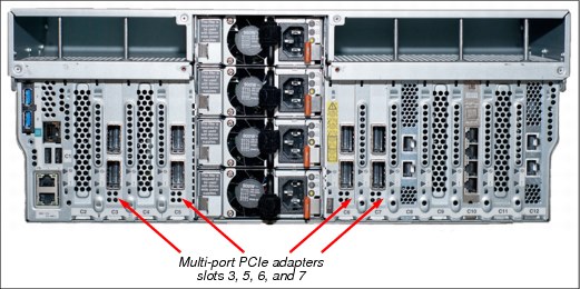
Figure 2-10 PCIe adapter locations in the DS8886 processor complex
Figure 2-11 shows the PCIe adapter locations in the DS8884 CPC.
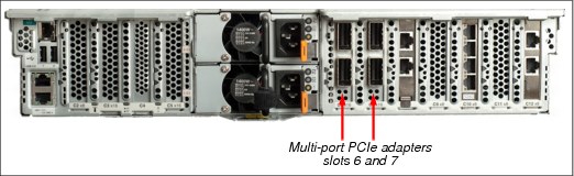
Figure 2-11 PCIe adapter locations in the DS8884 processor complex
2.4 I/O enclosures and adapters
The DS8880 base frame and first expansion frame (if installed) contain I/O enclosures, which are installed in pairs.
The DS8880 systems use an improved I/O enclosure, compared to earlier DS8000 systems. This new enclosure is PCIe Gen3-capable, and it is attached to the CPCs with PCIe Gen3 cables. The internal transfer rate to each I/O bay is four times faster than DS8870, which uses PCIe Gen2. The new I/O enclosure now supports six PCIe adapter slots, and it has PCIe attachments that allow direct attachment to the High-Performance Flash Enclosures.
DS8888 and DS8886 CPCs have up to four 2-port PCIe adapters that provide connectivity to the I/O enclosures. The DS8884 CPCs have two 2-port PCIe adapters that provide connectivity.
Figure 2-13 on page 40 and Figure 2-14 on page 41 show the DS8880 CPC to I/O enclosure connectivity. The DS8886 requires a dual 8-core configuration for the first expansion frame, and the DS8884 requires a 6-core processor with 128 GB of total system memory for the first expansion frame.
One or two I/O enclosure pairs can be installed in the base frame of the DS8886. The DS8884 has a single I/O enclosure pair. Two I/O enclosure pairs are installed in the first expansion frame of a DS8886 when it is installed. The DS8884 expansion frame has a single I/O enclosure pair.
A DS8886 has two I/O enclosure pairs in the base frame. A DS8884 system supports only one I/O enclosure pair in the base frame. For the DS8886, a dual 8-core system is required before the first expansion frame can be installed. This system supports the four I/O enclosure pairs in the first expansion frame.
Each I/O enclosure can have up to four HAs and two DAs. A maximum of 16 host adapter ports are supported in a single I/O enclosure. Flash interface cards are no longer installed in the I/O enclosure because the I/O enclosure has direct PCIe ports for direct attachment to the HPFE.
Each I/O enclosure includes the following attributes:
•5U rack-mountable enclosure
•Six PCIe slots
•Two PCIe Gen3 connections to the HPFE
•Redundant power and cooling
Figure 2-12 shows the DS8888 CPC to I/O enclosure connectivity.
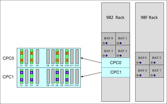
Figure 2-12 DS8888 I/O enclosure connections to the CPC
Figure 2-13 shows the DS8886 CPC to I/O enclosure connectivity.

Figure 2-13 DS8886 I/O enclosure connections to the CPC
Figure 2-14 shows the DS8884 CPC to I/O enclosure connectivity.

Figure 2-14 DS8884 I/O enclosure connections to the CPC
2.4.1 Cross-cluster communication
Figure 2-15 shows how the DS8880 I/O enclosure hardware is shared between the servers. One CPC is on the left side and one CPC is on the right side. The solid lines denote primary PCIe paths, while the dashed lines denote secondary PCIe paths.

Figure 2-15 DS8880 series PCIe communications paths as configured on the DS8886
The DS8880 uses the PCIe paths through the I/O enclosures to provide high-speed communication paths between the CPCs. Normally, the lowest available even-numbered I/O enclosure is used for communication from server 0 to server 1, whereas the lowest available odd-numbered I/O enclosure is used for communication from server 1 to server 0.
If a failure occurs in one or more I/O enclosures, any of the remaining enclosures can be used to maintain communication between the servers.
2.4.2 I/O enclosure adapters
The DS8880 I/O enclosures provide the connectivity from the hosts systems to the storage arrays through the processor complexes. Each I/O adapter is optimized for its specific task in the DS8880.
Each I/O enclosure can contain up to four HAs that provide attachment to host systems and up to two DAs to provide attachment for standard drive enclosures. Each I/O enclosure has two PCIe x8 connectors on the I/O enclosure PCIe module that provide attachment for the HPFEs. In DS8888, two additional PCIe x8 redrive cards can be installed in the third and sixth card slots.
Figure 2-16 shows the DS8880 I/O enclosure adapter layout for DS8888 (left) and DS8886 / DS8884 (right)

Figure 2-16 DS8888 (left) and DS8886 / DS8884 (right) I/O enclosure adapter layouts
DS8880 host adapters
Attached host servers interact with software that is running on the processor complexes to access data that is stored on logical volumes. The servers manage all read and write requests to the logical volumes on the storage arrays.
Two different types of HAs are available (8 Gbps and 16 Gbps). Both can negotiate their data transfer rate. 16 Gbps HAs can negotiate to 16, 8, or 4 Gbps full-duplex data transfer. The 8 Gbps HAs can negotiate to 8, 4, or 2 Gbps full-duplex. The 8 Gbps HAs can be either 4-port or 8-port cards. The 16 Gbps HAs are 4-port cards only.
Figure 2-17 shows the 16 Gbps host adapter. It provides faster single stream and per port throughput, and reduces latency in comparison to the 8 Gbps adapter. The 16 Gbps HA is equipped with a quad-core PowerPC processor that delivers dramatic (two to three times) full adapter input/output operations per second (IOPS) improvements compared to the 8 Gbps adapter.

Figure 2-17 Sixteen Gbps host adapter
|
Note: The maximum number of host adapter ports in any single I/O enclosure is 16, regardless of the HA type. If you install 8-port HAs, they are installed in slot 1 and 4 of the I/O enclosure.
|
HAs are installed in slots 1, 2, 4, and 5 of the I/O enclosure. Figure 2-16 on page 42 shows the locations for four 16 Gbps HA cards in the DS8880 I/O enclosure.
Each HA port can be configured as either FICON or FCP. For 8 Gbps HAs only, it is also possible to configure the port for the FC-AL protocol. For both HAs, the card optics can be either LW or SW.
The DS8888 and DS8886 configurations support a maximum of 16 HAs in the base frame, and an additional 16 HAs in the first expansion frame. The DS8884 configuration supports a maximum of eight in the base frame and an additional eight in the first expansion frame. With sixteen 8-port HAs, the maximum number is 128 HA ports. With sixteen 4-port HAs, the maximum number is 64 HA ports.
Eight Gbps HAs are available as 4-port and 8-port cards. The 16 Gbps HAs are available as 4-port cards only. The intermixture of both adapters is supported and leads to a different maximum number of ports, as shown on Table 2-1.
|
Optimum availability: To obtain optimum availability and performance, one HA must be installed in each available I/O enclosure before a second HA is installed in the same enclosure.
|
Table 2-1 DS8886 port configurations
|
16 Gbps
FC adapters
|
8 Gbps
FC adapters
|
16 Gbps
FC ports |
8 Gbps FC ports (4-port/8-port)
|
Maximum ports
|
|
0
|
16
|
0
|
64 - 128
|
128
|
|
1
|
15
|
4
|
60 - 120
|
124
|
|
2
|
14
|
8
|
56 - 112
|
120
|
|
3
|
13
|
12
|
52 - 104
|
116
|
|
4
|
12
|
16
|
48 - 96
|
112
|
|
5
|
11
|
20
|
44 - 88
|
108
|
|
6
|
10
|
24
|
40 - 80
|
104
|
|
7
|
9
|
28
|
36 - 72
|
100
|
|
8
|
8
|
32
|
32 - 64
|
96
|
|
9
|
7
|
36
|
28 - 56
|
92
|
|
10
|
6
|
40
|
24 - 48
|
88
|
|
11
|
5
|
44
|
20 - 40
|
84
|
|
12
|
4
|
48
|
16 - 32
|
82
|
|
13
|
3
|
52
|
12 - 24
|
78
|
|
14
|
2
|
56
|
8 - 16
|
74
|
|
15
|
1
|
60
|
4 - 8
|
70
|
|
16
|
0
|
64
|
0
|
64
|
Figure 2-18 shows the preferred HA installation order for the DS8880. The HA locations and installation order for the four I/O enclosures in the base frame are the same for the I/O enclosures in the first expansion frame. If 16-port HAs are installed, they fill the first and second HA pair only, and leave the additional two slots unused.

Figure 2-18 DS8880 HA installation order
Fibre Channel
The DS8880 uses the Fibre Channel protocol to transmit Small Computer System Interface (SCSI) traffic inside Fibre Channel frames. It also uses Fibre Channel to transmit FICON traffic, which uses Fibre Channel frames to carry z Systems I/O.
Each DS8880 Fibre Channel HA offers four or eight 8 Gbps Fibre Channel ports or four 16 Gbps Fibre Channel ports. Each port uses a LC-type connector. The 8 Gbps port independently auto-negotiates to an 8, 4, or 2 Gbps link speed. Sixteen Gbps ports can negotiate to a 16, 8, or 4 Gbps full-duplex data transfer. Each of the ports on a DS8880 HA can be independently configured for FCP or FICON. In addition, FC-AL can be configured on 8 Gbps ports only. The type of port can be changed through the DS8880 Storage Management GUI or by using data storage command-line interface (DS CLI) commands. A port cannot be FICON and FCP simultaneously, but the protocol can be changed as required.
The adapter itself is PCIe Gen 2. The HA contains a new high-performance application-specific integrated circuit (ASIC). To ensure maximum data integrity, it supports metadata creation and checking. Each Fibre Channel port supports a maximum of 509 host login IDs and 1,280 paths. This configuration allows the creation of large storage area networks (SANs).
Fibre Channel-supported servers
The current list of servers that are supported by Fibre Channel attachment is available at this website:
Consult these documents regularly because they contain the current information about server attachment support.
Fibre Channel distances
The following types of HA cards are available:
•LW
•SW
All ports on each card must be LW or SW. No intermixing of the two types within an adapter is allowed. With LW, you can connect nodes at distances of up to 10 km (6.2 miles) (non-repeated). With SW, you are limited to a distance that depends on the Fibre Channel cable type and the data transfer rate. OM3 Fibre Channel cable is required with 8 Gbps HAs and 16 Gbps HAs. For 16 Gbps, use OM3 or OM4. For the link distance limitations, see Table 2-2.
Table 2-2 SW link distance
|
Speed
|
OM3 link distance
|
OM4 link distance
|
|
8 Gbps FC
|
150 m (492 ft.)
|
190 m (623.3 ft.)
|
|
16 Gbps FC
|
100 m (328 ft.)
|
125 m (410.1 ft.)
|
Device adapters
DAs are Redundant Array of Independent Disks (RAID) controllers that provide access to the installed drives in the standard drive enclosures.
Each of the DS8880 DAs has four 8 Gbps Fibre Channel ports, which are connected to the drive enclosures by using two dual FC-AL loops, by using a switched topology. The DAs are installed in the I/O enclosures, and they are connected to the processor complexes through the PCIe network. The DAs are responsible for managing, monitoring, and rebuilding the RAID arrays. The DAs provide remarkable performance because of a high function and high-performance ASIC. To ensure maximum data integrity, the adapter supports metadata creation and checking.
Each DA connects the processor complexes to two separately switched FC-AL networks. Each network attaches to standard drive enclosures. Every drive in the enclosure is connected to both networks. Whenever the DA connects to a drive, it uses a bridged connection to transfer data. Figure 2-16 on page 42 shows the locations of the DAs in the I/O enclosure.
The DS8886 configuration supports 1 - 4 DA pairs in the base frame, and up to 4 additional DA pairs in the first expansion frame, for a total of up to 8 DA pairs. The DS8884 configuration supports half of the DS8886 configuration, or 1 - 2 DA pairs in the base frame, and up to 2 additional DA pairs in the first expansion frame, for a total of up to 4 DA pairs.
2.5 Storage enclosures and drives
This section covers the storage enclosures and drives, which consist of the following components:
•The installed flash cards, flash drives, and rotational drives, which are commonly referred to as disk drive modules (DDMs).
•Flash interface card pairs (DS8888 only) and DA pairs:
– The flash interface card pairs extend the I/O enclosure PCIe bus to the HPFEs.
– The DA pairs connect to Fibre Channel interface cards (FCICs) in the standard drive enclosures. These connections create switched arbitrated loop Fibre Channel networks to the installed drives.
For more information about the storage subsystem, see 3.5, “RAS on the storage subsystem” on page 78.
2.5.1 Drive enclosures
The DS8880 has two types of drive enclosures:
•HPFEs
•Standard drive enclosures
High-performance flash enclosures
The DS8880 HPFE is a high-speed, 1U enclosure that contains dual integrated flash RAID controllers that are optimized for flash. Each HPFE can support either 16 (half populated) or 30 (fully populated) flash cards. The I/O enclosure uses PCIe connectivity over two x8 PCIe Gen2 cables to the flash RAID controllers.
HPFEs are installed in single increments. The DS8888 configuration can support up to eight HPFEs in the base frame, and up to eight HPFEs in the optional expansion frame, for a total of 16 HPFEs, with a maximum 480 flash cards.
The DS8886 configuration can support up to four HPFEs in the base frame, and up to four HPFEs in the first expansion frame, for a total of 8 HPFEs, with a maximum 240 flash cards.
The DS8884 configuration can support up to two HPFEs in the base frame, and up to two HPFEs in the first expansion frame, for a total of 4 HPFEs, with a maximum 120 flash cards.
Figure 2-19 on page 47 shows the HPFE. The covers are removed to show key components.
To learn more about the HPFE, see System x3630 M4 (E5-2400 v2), TIPS1145:

Figure 2-19 Cut-away view of the HPFE that shows key components
PCIe bus attachment
The dual integrated flash RAID controllers in the DS8880 HPFE are connected to the PCIe module in two different I/O enclosures to provide redundancy and workload balance. In the DS8888, flash interface cards can also be installed in the third and sixth slots to provide additional connectivity.
The x8 PCIe Gen2 connections provide up to 4 GBps, full duplex, data transfer rates to the enclosure, with none of the protocol processor burden that is associated with Fibre Channel architecture. Each I/O enclosure pair supports up to four HPFEs in DS8888, or up to two HPFEs in DS8886 and DS8884. Figure 2-20 shows a simplified view of the PCIe cabling topology.

Figure 2-20 High-performance flash enclosure PCIe cabling
High-performance flash cards
The DS8880 HPFE supports 1.8-inch high-performance flash cards (Table 2-3).
The high-performance flash cards can be only installed in HPFEs. Each HPFE can contain 16 or 30 flash cards. Flash card set A (16 flash cards) is required for each flash enclosure. Flash card set B (14 flash cards) is an optional feature that can be ordered to fully populate the flash enclosure with a maximum of 30 flash cards. All flash cards in a flash enclosure must be the same type and same capacity.
All high-performance flash cards are Full Disk Encryption (FDE) capable. For more information about licensed features, see Chapter 9, “IBM DS8880 features and licensed functions” on page 217.
Table 2-3 Supported high-performance flash cards
|
Feature code
|
Drive capacity
|
Drive type
|
Drive speed in RPM (K=1000)
|
RAID support
|
|
15961
|
400 GB
|
1.8-inch flash card
|
N/A
|
5, 10
|
|
15982
|
400 GB
|
1.8-inch flash card
|
N/A
|
5, 10
|
|
1516a
|
800 GB
|
1.8-inch flash card
|
N/A
|
5, 10
|
|
1518b
|
800 GB
|
1.8-inch flash card
|
N/A
|
5, 10
|
1 FlashCard set A: Required for each HPFE (Feature Code (FC) 1500).
2 FlashCard set B: Optional with FC1596 or FC1516. If FC1598 or FC 1518 is not ordered, a filler set is required.
|
Note: To learn more about the DS8880 drive features, see the IBM System Storage DS8880 Introduction and Planning Guide, GC27-8525.
|
Arrays and spares
Each HPFE can contain up to four array sites. The first set of 16 flash cards creates two 8-flash card array sites. During logical configuration, RAID 5 arrays and the required number of spares are created. The number of required spares for an HPFE is two. The first two arrays to be created from these array sites are 6+P+S. The next set of 14 flash cards creates two 7-flash card array sites. These next two RAID 5 arrays to be created from these array sites are 6+P.
The HPFE supports RAID 5 and RAID 10 arrays. For more information about DS8880 virtualization and configuration, see Chapter 4, “Virtualization concepts” on page 93.
2.5.2 Standard drive enclosures
The DS8880 traditional spinning drives, which are also known as DDMs, and flash drives, which are also known as solid-state drives (SSDs), are installed in standard drive enclosures.
The DS8880 standard drive enclosures are installed as pairs. Depending on whether it is a base frame, first expansion frame, or other expansion frame, that frame can contain either 4, 6, or 9 standard drive enclosure pairs in the DS8886, and 5 or 6 standard drive enclosure pairs in a DS8884.
A standard drive enclosure pair supports either twenty-four 2.5-inch small form factor (SFF) or twelve 3.5-inch large form factor (LFF) drives. Each drive is an industry-standard serial-attached SCSI (SAS) drive.
Flash drives can be installed in standard drive enclosure pairs in drive sets of 8 or 16, depending on the capacity of the drive. The 2.5-inch SFF drives are installed in drive sets of 16. The 3.5-inch LFF drives are in installed in drive sets of eight.
Half of each drive set is installed in each enclosure of the enclosure pair.
|
Note: If the standard drive enclosure pair is not fully populated, you must install fillers in the empty slots.
|
Each drive connects into the enclosure midplane. The midplane provides physical connectivity for the drives, FCICs, and power supply units (PSUs).
Each drive enclosure has a redundant pair of FCICs with two inbound and two outbound 8 Gbps Fibre Channel (FC) connections. The FCICs provide the Fibre Channel to SAS conversion and interconnection logic for the drives. In addition, the FCICs include SCSI Enclosure Services (SES) processors that provide all enclosure services.
Figure 2-21 shows the front and rear views of the standard drive enclosure.
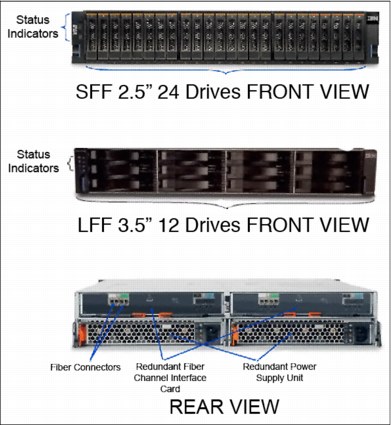
Figure 2-21 DS8880 standard drive enclosures
Switched Fibre Channel Arbitrated Loop
The DS8880 uses switched FC-AL technology to link the Fibre Channel DA pairs to the standard drive enclosures. Switched FC-AL uses the standard FC-AL protocol. However, the physical implementation is different. Switched FC-AL technology includes the following key features:
•Standard FC-AL communication protocol from the DA to drives.
•Direct point-to-point connections are established between the DA and drives.
•Isolation capabilities to provide easy problem determination during drive failures.
•Predictive failure statistics.
•Simplified expansion, where no cable rerouting is required when additional drive enclosure pairs are installed to the Fibre Channel network. The DS8880 architecture uses dual redundant switched FC-AL access to each of the drive enclosures. This configuration features the following key benefits:
– Two independent switched FC-AL networks provide high-performance connections to the drives.
– Four access paths are available to each drive.
– Each DA port operates independently.
– This configuration doubles the bandwidth over traditional FC-AL loop implementations.
Figure 2-22 shows each drive attached to two separate FCICs with connections to the drives. By using two DAs, redundant data paths exist to each drive. Each DA can support two switched Fibre Channel networks.

Figure 2-22 DS8880 drive enclosure (only 16 drives are shown for simplicity)
Arrays across loops
Figure 2-23 shows the DA pair layout. One DA pair creates two dual switched loops.

Figure 2-23 DS8880 switched loop layout (only eight drives per enclosure are shown for simplicity)
For the DS8880, the upper enclosure connects to one dual loop and the lower enclosure connects the other dual loop, in a drive enclosure pair.
Each enclosure places two FC switches onto each dual loop. Drives are installed in groups of 16. Half of the new drives are installed in one drive enclosure, and the other half is placed into the other drive enclosure of the pair.
A standard drive enclosure array site consists of eight drives: Four from each enclosure of the pair. When a RAID array is created from the drives of an array site, half of the array is in each storage enclosure. The performance is increased because the bandwidth is aggregated across the hardware of both enclosures.
One storage enclosure of the pair is on one FC switched loop, and the other storage enclosure of the pair is on a second switched loop. This configuration splits the array across two loops, which is known as array across loops (AAL), as shown in Figure 2-24 on page 52. Only 16 drives are shown, with eight in each drive enclosure. When fully populated, 24 drives are in each enclosure.
Figure 2-24 shows the layout of the array sites. Array site 1 in green (the darker drives) consists of the four left drives in each enclosure. Array site 2 in yellow (the lighter disks) consists of the four right drives in each enclosure. When an array is created, the array is accessible across both dual loops.

Figure 2-24 Array across loop
Benefits of AAL
AAL is implemented to increase performance. When the DA writes a stripe of data to a RAID 5 array, it sends half of the write to each switched loop. By splitting the workload in this manner, the workload is balanced across the loops. This configuration aggregates the bandwidth of the two loops and improves performance. If RAID 10 is used, two RAID 0 arrays are created. Each loop hosts one RAID 0 array. When the read I/O is serviced, half of the reads can be sent to each loop, which improves performance by balancing the workload across the loops.
Expansion
Device adapters (DAs) are installed in the I/O enclosures in pairs. Each DA of the pair is in a separate I/O enclosure of the I/O enclosure pair. The DS8886 configuration can support up to four DA pairs in the base frame, and four DA pairs in the first expansion frame for a total of eight DA pairs. The DS8884 configuration can support up to two DA pairs in the base frame, and two DA pairs in the first expansion frame, for a total of four DA pairs.
Standard drive enclosure pairs are connected to a DA pair. Each DA pair can support up to four drive enclosure pairs. If more storage capacity is required, an additional DA pair can be installed (up to the maximum supported quantity), and then additional standard drive enclosure pairs can be installed (up to the maximum supported quantity).
Drive sets can also be added to standard drive enclosures that are not fully populated. Half of the drive set is added to each enclosure of the drive enclosure pair. Performance will be superior if drive enclosure pairs are distributed across more DA pairs, aggregating the bandwidth of the installed hardware.
For more information about DA pairs and standard drive enclosure distribution and cabling, see 2.2.1, “DS8888 All-Flash configuration” on page 26 and 2.2.3, “DS8884 configuration” on page 28.
DS8880 standard and flash drives
•1.8-inch high-performance flash cards (see “High-performance flash cards” on page 48)
•2.5-inch SAS flash drives, which are also known as SSDs
•2.5-inch SAS enterprise drives (15K or 10K revolutions per minute (RPM))
•3.5-inch SAS nearline drives (7200 RPM)
Table 2-4 DS8880 supported enterprise and nearline drive types
|
Feature code
|
Drive capacity
|
Drive type
|
Drive speed in RPM (K=1000)
|
RAID support
|
Drives for each set
|
|
5308
|
300 GB
|
2.5-inch SAS Ent
|
15K
|
5, 6, and 10
|
16
|
|
5708
|
600 GB
|
2.5-inch SAS Ent
|
10K
|
5, 6, and 10
|
16
|
|
5618
|
600 GB
|
2.5-inch SAS Ent
|
15K
|
5, 6, and 10
|
16
|
|
5768
|
1.2 TB
|
2.5-inch SAS Ent
|
10K
|
5, 6, and 10
|
16
|
|
5778
|
1.8 TB
|
2.5-inch SAS Ent
|
10K
|
5, 6, and 10
|
16
|
|
5868
|
4 TB
|
3.5-inch SAS NL
|
7.2K
|
5 and 61
|
8
|
|
5878
|
6 TB
|
3.5-inch SAS NL
|
7.2K
|
5 and 6a
|
8
|
1 RAID 10 support is by request for price quotation (RPQ) only.
Table 2-5 shows the flash drive types supported by DS8880.
Table 2-5 DS8880 supported flash drive types
|
Feature code
|
Drive capacity
|
Drive type
|
Drive speed in RPM (K=1000)
|
RAID support1
|
Drives for each set
|
|
6068
|
200 GB
|
Flash drive (SSD)
|
N/A
|
5 and 10
|
16
|
|
6158
|
400 GB
|
Flash drive (SSD)
|
N/A
|
5 and 10
|
16
|
|
6258
|
800 GB
|
Flash drive (SSD)
|
N/A
|
5 and 10
|
16
|
|
6358
|
1.6 TB
|
Flash drive (SSD)
|
N/A
|
5 and 10
|
16
|
|
6458
|
3.2 TB
|
Flash drive (SSD)
|
N/A
|
5 and 10
|
16
|
1 RAID 6 or 10 is by RPQ only.
Arrays and spares
During logical configuration, arrays and spares are created from groups of eight drives, which are called array sites. The required number of spares for each DA pair is four drives of the same capacity and speed. For example, the first four RAID 5 arrays that are created are 6+P+S. Additional RAID 5 arrays (of the same capacity and speed) that are configured on the DA pair are 7+P.
The next group of 16 drives creates two 8-drive array sites. These next two arrays to be created from these array sites are 7+P. The HPFE supports only RAID 5 arrays. For more information about DS8880 virtualization and configuration, see Chapter 4, “Virtualization concepts” on page 93.
2.6 Power and cooling
The DS8880 power and cooling system is highly redundant. The components are described in this section. For more information, see 3.6, “RAS on the power subsystem” on page 86.
2.6.1 Rack Power Control
The DS8880 features a pair of redundant rack power control (RPC) cards, which are used to control the power sequencing of the system. As in earlier DS8000 models, the DS8880 RPCs are connected to the FSP in each processor complex, which allows them to communicate to the HMC and the storage system. The DS8880 RPC cards also add a second communication path to each of the processor complex operating partitions. The DS8880 RPCs also feature dedicated communication paths to each DC-UPS.
2.6.2 Direct current uninterruptible power supply
Each DS8880 frame contains two DC-UPSs. Depending on model configuration, these can be either single-phase 8 KW 8U DC-UPSs, or three-phase, 12 KW 12U DC-UPSs. The DC-UPSs cannot be intermixed in any DS8880 storage system.
The DC-UPS provides rectified AC power distribution and power switching for redundancy. Two redundant DC-UPSs are in each frame of the DS8880. Each DC-UPS features internal fans to supply cooling for that power supply.
The frame features two AC power cords. Each cord feeds a single DC-UPS. The DC-UPS distributes rectified AC. If AC is not present at the input line, the partner DC-UPS can provide rectified AC to the DC-UPS that lost input power, with no reduction in DC-UPS redundancy. If no AC input is present for either DC-UPS in the frame, the DC-UPSs switch to battery power. Depending on whether the ePLD feature is installed on the system, the system runs on battery power for either 4 or 40 seconds before it initiates an orderly shutdown.
2.6.3 Battery service module set
The DC-UPS contains integrated battery sets that are known as BSM sets. The BSM set consists of four BSM modules. The BSM sets help protect data if external power to the frame is lost. If AC input power to the frame is lost, the batteries are used to maintain power to the processor complexes and I/O enclosures for sufficient time to allow the contents of NVS memory (modified data that is not yet destaged from cache) to be written to the hard disk drives that are internal to the processor complexes (not the storage enclosure drives).
The BSMs sets consist of two BSM types:
•Each BSM set contains one primary BSM. The primary BSM is the only BSM with an electrical connection to the DC-UPS.
•Each BSM set also contains three secondary BSMs that are cabled to the primary BSM.
2.6.4 Extended Power Line Disturbance feature
The duration that the DC-UPSs can run on battery before system shutdown is initiated depends on whether the ePLD feature is installed.
The optional ePLD feature allows the system to run for up to 40 seconds without line input power and then gracefully shuts down the system if power is not restored. If the ePLD feature is not installed, the system initiates shutdown after 4 seconds if frame power is not restored. For more information about why this feature might be necessary, see 3.6.3, “Line power fluctuation” on page 89.
2.6.5 Power cord options
The power cord must be ordered specifically for the input voltage to meet certain requirements. The power cord connector requirements vary widely throughout the world. The power cord might not include the suitable connector for the country in which the system is installed. In this case, the connector must be replaced by an electrician after the system is delivered. For more information, see the IBM System Storage DS8880 Introduction and Planning Guide, GC27-8525.
2.6.6 Power distribution
In each frame, the two DC-UPSs supply output power to four Power Distribution Units (PDUs).
In the base frame, the PDUs supply power to the processor complexes, the I/O enclosures, the standard drive enclosures, and the HPFEs. In the first expansion frame, the PDUs supply power to the I/O enclosures, standard drive enclosures, and the HPFEs. In the second and third expansion frames, the PDUs supply power only to the standard drive enclosures. No HPFEs, I/O enclosures, or processor complexes are in these frames.
2.6.7 Enclosure power supplies
The CPCs, I/O enclosures, standard drive enclosures, and HPFEs feature dual redundant PSUs for each enclosure. The PSUs are supplied power from the DC-UPS through the PDUs. Each PSU in an enclosure is supplied from different DC-UPSs for redundancy. The PSUs have their own internal cooling fans. Each enclosure also has its own redundant cooling fans. All cooling fans draw cool air from the front of the frame and exhaust hot air to the rear of the frame.
|
Note: The DS8880 is designed for efficient air flow and to be compliant with hot and cold aisle data center configurations.
|
2.6.8 Power junction assembly
The power junction assembly (PJA) is a component of the DS8880 power subsystem. Dual PJAs provide redundant power to the Management Console (HMC) and the Ethernet switches.
2.7 Management Console and network
All configuration base frames ship with one Management Console, which is also known as the HMC, and two private network Ethernet switches. An optional second Management Console is available as a redundant point of management, and is also installed in the base frame. The introduction of the 19-inch rack introduced a new HMC, which is an SFF mini PC HMC.
Figure 2-25 shows a diagram of the new mini PC HMC and its location in the base frame. The mini PC HMC resides in the bottom of the base frame. As an option, a redundant HMC is available. This secondary HMC no longer needs to be added to a customer rack. This secondary HMC sits next to the primary HMC.

Figure 2-25 Diagram of new mini PC HMC and location in the base frame
The storage administrator runs all DS8880 logical configuration tasks by using the Storage Management GUI or DS CLI. All client communications to the storage system are through the HMC.
Clients that use the DS8880 advanced functions, such Metro Mirror or FlashCopy, for example, communicate to the storage system with Copy Services Manager (CSM). CSM is built into Spectrum Control Standard and Advanced. It replaces the IBM Tivoli Productivity Center for Replication through the Management Console.
The Management Console provides connectivity between the storage system and Encryption Key Manager (EKM) servers.
The Management Console also provides the functions for remote call-home and remote support connectivity.
For more information about the HMC, see Chapter 8, “IBM DS8880 Management Console planning and setup” on page 201.
2.7.1 Ethernet switches
The DS8880 base frame has two 8-port Ethernet switches. The two switches provide two redundant private management networks. Each CPC includes connections to each switch to allow each server to access both private networks. These networks cannot be accessed externally, and no external connections are allowed. External client network connection to the DS8880 system is through a dedicated connection to the Management Console. The switches receive power from the PJAs and do not require separate power outlets. The ports on these switches are shown in Figure 2-26.

Figure 2-26 Ethernet switch ports
|
Important: The internal Ethernet switches that are shown in Figure 2-26 are for the DS8880 private network only. No client network connection must ever be made directly to these internal switches.
|
2.7.2 DS8880 operator panel
The DS8880 status indicators are on the front door. Figure 2-27 shows the operator panel for a DS8880 storage system.
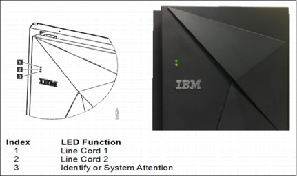
Figure 2-27 DS8880 frame operator indicators
Each panel has two power cord indicators, one for each power cord (frame input power). For normal operation, both of these indicators are illuminated green if each power cord supplies the correct power to the frame. Another LED is below the line indicators with a normal state of off. If this LED is lit solid yellow (in only the base frame), an open event exists in the problem log, and service is required. If this LED flashes (in any frame), the frame is being serviced.
The DS8880 has no physical power on/off switch because power sequencing is managed through the HMC. This configuration ensures that all data in nonvolatile storage, which is known as modified data, is destaged correctly to the drives before the DS8880 powers down.
2.8 Hardware feature summary for DS8880 configurations
The following tables summarize the hardware features that are available for the different DS8880 configurations.
The DS8888 is a high-performance All-Flash storage system that uses only High- Performance Flash Enclosures. Table 2-6 shows the hardware features of the DS8888.
Table 2-6 Hardware features of the DS8888
|
Processor
cores
|
System
memory1
|
Maximum
I/O
enclosure
pairs
|
Host
adapters2
|
Device adapter pairs
|
HPFEs
|
Maximum standard
drive
enclosure
pairs
|
Expansion
frames
|
|
24-core
|
1024 GB
|
4
|
2 - 16
|
0
|
2 - 8
|
0
|
0
|
|
48-core
|
2048 GB
|
8
|
2 - 32
|
0
|
2 - 16
|
0
|
0 - 1
|
1 System memory for each CPC.
2 Host adapters can be four ports or eight ports, with a maximum of 16 ports for each I/O enclosure.
Table 2-7 shows the maximum capacities for the Enterprise Class configuration
Table 2-7 Maximum capacity for the DS8888 configuration
|
Processor
cores
|
System
memory1
|
Maximum quantity of
2.5-inch
drives
|
Maximum usable
capacity of
2.5-inch
drives
|
Maximum quantity of
3.5-inch
drives
|
Maximum
usable
capacity of
3.5-inch
drives
|
Maximum
quantity of 1.8-inch flash cards
|
Maximum
usable
capacity of
1.8-inch
flash cards2
|
Maximum
total number of drives
|
|
24-core
|
1024 GB
|
0
|
0
|
0
|
0
|
240
|
73.25 TB
|
n/a
|
|
48-core
|
2048 GB
|
0
|
0
|
0
|
0
|
480
|
146.5 TB
|
n/a
|
1 System memory for each CPC.
2 Usable capacity is calculated by using RAID 5 for 1.8-inch flash cards.
The DS8886 is a high-density, high-performance storage system that includes standard disk enclosures and High-Performance Flash Enclosures. Table 2-8 shows the hardware features for the DS8886 configuration.
Table 2-8 Hardware features of the DS8886
|
Processor
cores
|
System
memory1
|
Maximum
I/O
enclosure
pairs
|
Host
adapters2
|
Device adapter pairs
|
HPFEs
|
Maximum standard
drive
enclosure
pairs
|
Expansion
frames
|
|
8-core
|
128 GB
|
4
|
2 - 16
|
1 - 4
|
0 - 4
|
6
|
0
|
|
8-core
|
256 GB
|
4
|
2 - 16
|
1 - 4
|
0 - 4
|
6
|
0
|
|
16-core
|
256 GB
|
8
|
2 - 32
|
1 - 8
|
0 - 8
|
32
|
0 - 4
|
|
16-core
|
512 GB
|
8
|
2 - 32
|
1 - 8
|
0 - 8
|
32
|
0 - 4
|
|
24-core
|
1024 GB
|
8
|
2 - 32
|
1 - 8
|
0 - 8
|
32
|
0 - 4
|
|
24-core
|
2048 GB
|
8
|
2 - 32
|
1 - 8
|
0 - 8
|
32
|
0 - 4
|
1 System memory for each CPC.
2 Host adapters can be four ports or eight ports, with a maximum of 16 ports for each I/O enclosure.
Table 2-9 shows the maximum capacities for the Enterprise Class configuration.
Table 2-9 Maximum capacity for the DS8886 configuration
|
Processor
cores
|
System
memory1
|
Maximum quantity of
2.5-inch
drives
|
Maximum usable
capacity of
2.5-inch
drives2
|
Maximum quantity of
3.5-inch
drives
|
Maximum
usable
capacity of
3.5-inch
drives3
|
Maximum
quantity of 1.8-inch flash cards
|
Maximum
raw/usable
capacity of
1.8-inch
flash cards4
|
Maximum
total number of drives5
|
|
8-core
|
128 GB
|
192
|
259.5 TB
|
96
|
384 TB
|
120
|
36.6 TB
|
312
|
|
8-core
|
256 GB
|
192
|
259.5 TB
|
96
|
384 TB
|
120
|
36.6 TB
|
312
|
|
16-core
|
256 GB
|
1536
|
2.24 PB
|
768
|
3.04 PB
|
240
|
73.25 TB
|
1776
|
|
16-core
|
512 GB
|
1536
|
2.24 PB
|
768
|
3.04 PB
|
240
|
73.25 TB
|
1776
|
|
24-core
|
1024 GB
|
1536
|
2.24 PB
|
768
|
3.04 PB
|
240
|
73.25 TB
|
1776
|
|
24-core
|
2048 GB
|
1536
|
2.24 PB
|
768
|
3.04 PB
|
240
|
73.25 TB
|
1776
|
1 System memory for each CPC.
2 Usable capacity is calculated by using RAID 5 for 2.5-inch drives.
3 Usable capacity is calculated by using RAID 6 for 3.5-inch nearline (NL) drives.
4 Usable capacity is calculated by using RAID 5 for 1.8-inch flash cards.
5 Combined total of 2.5-inch disk drives and 1.8-inch flash cards.
The DS8884 is an entry-level, high-performance storage system that includes standard disk enclosures and high-performance flash enclosures.
Table 2-10 shows the hardware features for the DS8884.
Table 2-10 Hardware features for the Business Class configuration
|
Processor
cores
|
System
memory1
|
Maximum I/O of
enclosure
pairs
|
Host
adapters2
|
Device adapter pairs
|
HPFEs
|
Maximum standard
drive
enclosure
pairs
|
Expansion
frames
|
|
6-core
|
32 GB
|
2
|
2 - 8
|
1 - 2
|
0 - 2
|
6
|
0
|
|
6-core
|
64 GB
|
2
|
2 - 16
|
1 - 4
|
0 - 2
|
18
|
0 - 2
|
|
6-core
|
128 GB
|
2
|
2 - 16
|
1 - 4
|
0 - 2
|
18
|
0 - 2
|
1 System memory for each CPC.
2 Host adapters can be four ports or eight ports, with a maximum of 16 ports for each I/O enclosure.
Table 2-11 shows the maximum capacities for the DS8884 configuration.
Table 2-11 Maximum capacities for the DS8884 configuration
|
Processor
cores
|
System
memory1
|
Maximum quantity of
2.5-inch
drives
|
Maximum
usable capacity of
2.5-inch
drives2
|
Maximum quantity of
3.5-inch
drives
|
Maximum
usable capacity of
3.5-inch
drives3
|
Maximum quantity of
1.8-inch
flash cards
|
Maximum
usable capacity of
1.8-inch
flash cards4
|
Maximum
total
drives5
|
|
6-core
|
64 GB
|
240
|
345 TB
|
120
|
458 TB
|
60
|
18.3 TB
|
300
|
|
6-core
|
128 GB
|
768
|
1.12 PB
|
384
|
1.52 PB
|
120
|
36.6 TB
|
888
|
|
6-core
|
256 GB
|
768
|
1.12 PB
|
384
|
1.52 PB
|
120
|
36.6 TB
|
888
|
1 System memory for each CPC.
2 Usable capacity is calculated by using RAID 5 for 2.5-inch drives.
3 Usable capacity is calculated by using RAID 6 for 3.5-inch NL drives.
4 Usable capacity is calculated by using RAID 5 for 1.8-inch flash cards.
5 Combined total of 2.5-inch disk drives and 1.8-inch flash cards.
..................Content has been hidden....................
You can't read the all page of ebook, please click here login for view all page.