

iSCSI/FC storage
This chapter shows a realistic example for block based storage using iSCSI storage that consists of a Clustered Data ONTAP system and a Windows 2008 server having several Ethernet ports. The approach for Fibre Channel (FC) is very similar.
We show you how to configure a storage virtual machine (SVM) for a Windows iSCSI host.
In the Clustered Data ONTAP 8.2 operating system, iSCSI is currently supported in clusters of up to eight nodes.
The following topics are covered:
22.1 Planning and checking the iSCSI environment
In this chapter, you will create an SVM for a Windows 2008 iSCSI host through an OnCommand System Manager GUI. According to the official procedure, you will check the interoperability and configure both a Windows 2008 host and a Clustered Data ONTAP system.
22.1.1 Checking your environment before configuration of iSCSI
Before configuring iSCSI, you will need to perform several checks as described next.
Checking the interoperability
Here is the link to the N series interoperability matrix:
In this case, we will check the interoperability between Windows 2008 and Clustered Data ONTAP. You can check iSCSI interoperability with the following link, which is included in the prior link:
The support information is organized into the following topics in this interoperability matrix:
•Host Utilities version
•Certified Windows version
•Supported CPU types
•Information and alerts:
In this topic, you will find important information regarding OS patches, considerations,
and so on.
and so on.
|
Note: It is crucial to check the interoperability before the implementation and the planning phase. If you cannot find any certified solution, you must submit a SCORE/RPQ (Request for Price Quotations). To submit a SCORE/RPQ, contact your IBM Representative.
|
22.2 Configuring iSCSI for both Windows 2008 and Clustered Data ONTAP
In a Clustered Data ONTAP environment, you must create an SVM to provide iSCSI services to the host. We assume that you already know how to configure the basic cluster system.
22.2.1 Creating an SVM for iSCSI
To provide iSCSI services to specific hosts, you must create at least one SVM for iSCSI services. In this case, you will create one SVM for one Windows 2008 server.
Creating an SVM for iSCSI
To create an SVM, proceed as follows:
1. Click Vservers in the System Manager navigation frame.
Figure 22-1 Create an SVM for iSCSI
3. Next you see the Vserver Setup wizard as shown in Figure 22-2. You need to enter an SVM name and several options in this window.
Here we list some values to be entered:
– Vserver Name: Define a name for the SVM that you want to name.
– Data Protocols: Each SVM can be a server that provides multiple protocols or at least one protocol. In this chapter, select iSCSI only.
– Language: This parameter depends on the specific characters that are used by your language environment. The default language is set to C.UTF-8. If your country uses two-byte characters, select a correct one.
|
Note: The language of an SVM with FlexVol volumes can be modified after the SVM is created.
|
– Security style: There are three security styles. UNIX, NTFS, and Mixed are the options. You can decide what security style to use on a volume, and you should consider two factors. The primary factor is the type of administrator that manages the file system. The secondary factor is the type of user or service that accesses the data on the volume.
– Root Aggregate: Select a root aggregate from one of the node root aggregates.
4. When you have made your selections, click the Submit & Continue button.

Figure 22-2 VServer Setup - Details Setup
After completing the prior steps, you can configure iSCSI logical interfaces (LIFs) as follows (see Figure 22-3):
1. In this panel, you can configure a data interface LIF for iSCSI.
|
Note: You can configure the iSCSI protocol while creating the SVM or you can do so at a later time.
|
Here we explain some values that you can choose:
– Target Alias: Specify an alias for the iSCSI target.
|
Note: The maximum number of characters for an alias name is 128. If you do not specify a target alias, the SVM name is used as an alias.
|
– LIFs Per Node: Specify the number of iSCSI LIFs that can be assigned to a single node. The minimum number for LIFs per node is two. The maximum number is the minimum of all the ports in the up state across the nodes. If the maximum value is an odd number, the previous even number is considered as the maximum value. You can choose any even number in the minimum and maximum value range.
|
Note: Do not manually enter the value. You must the select a value from the list.
Example: A 4-node cluster has node1, node2, and node3 with 4 ports each in the up state, and node4 with 5 ports in the up state. The effective maximum value for the cluster is 4.
|
– Starting IP Address: Specify the starting network IP address. The starting IP address specifies the first of the contiguous addresses in the LIF IP address pool.
|
Note: If you specify the number 4 for LIFs Per Node, the GUI will use a series of IP addresses as the starting IP address specified by you.
Example: If you specify the IP address of 9.155.66.65, the rest of the IP addresses should be 9.155.66.66, 67, 68. If you do not want to use a series of IP addresses, make the LIF manually through the CLI or click the check box, Review or Modify LIFs configuration (Advanced Settings).
|
– Netmask: Specify the subnet mask.
– Gateway:Specify the default gateway address.
– Number of portsets: If you want to verify or modify the automatically generated iSCSI LIFs configuration, select Review or Modify LIFs configuration (Advanced Settings). You can modify only the LIF name, home port, and LIF IP address. By default, the portsets are set to the minimum value.
You must ensure that you do not specify duplicate entries. If you specify duplicate LIF names, the System Manager appends numeric values to the duplicate LIF name. Based on the selected portset, the LIFs are distributed across the portsets using a round-robin method to ensure redundancy in case of node or port failure.
2. Then click the Submit & Continue button.

Figure 22-3 Configure iSCSI protocol
3. After clicking the Submit & Continue button, the iSCSI LIFs and portsets are created with the specified configuration. The LIFs are distributed accordingly among the portsets. The iSCSI service is started if all the LIFs are successfully created. See Example 22-1 to check the result through the CLI.
Example 22-1 A command to check iSCSI LIFs
cdot-cluster01::> network interface show
Logical Status Network Current Current Is
Vserver Interface Admin/Oper Address/Mask Node Port Home
----------- ---------- ---------- ------------------ ------------- ------- ----
cdot-cluster01
cluster_mgmt up/up 9.155.66.34/24 cdot-cluster01-02
e0a false
cdot-cluster01-01
clus1 up/up 169.254.216.146/16 cdot-cluster01-01
e2a true
clus2 up/up 169.254.67.99/16 cdot-cluster01-01
e2b true
mgmt1 up/up 9.155.90.168/24 cdot-cluster01-01
e0M true
cdot-cluster01-02
clus1 up/up 169.254.45.229/16 cdot-cluster01-02
e2a true
clus2 up/up 169.254.250.11/16 cdot-cluster01-02
e2b true
mgmt1 up/up 9.155.90.169/24 cdot-cluster01-02
e0M true
vs_cifs_01
vs_cifs_01_cifs_lif1
up/up 9.155.66.31/24 cdot-cluster01-02
Press <space> to page down, <return> for next line, or 'q' to quit...
e0a true
Logical Status Network Current Current Is
Vserver Interface Admin/Oper Address/Mask Node Port Home
----------- ---------- ---------- ------------------ ------------- ------- ----
vs_iSCSI_01
cdot-cluster01-01_iscsi_lif_1
up/up 9.155.66.65/24 cdot-cluster01-01
e0b true
cdot-cluster01-01_iscsi_lif_2
up/up 9.155.66.66/24 cdot-cluster01-01
e0a true
cdot-cluster01-02_iscsi_lif_1
up/up 9.155.66.67/24 cdot-cluster01-02
e0b true
cdot-cluster01-02_iscsi_lif_2
up/up 9.155.66.68/24 cdot-cluster01-02
e0a true
vs_nfs_01
cdot_cluster_01_01_lif_01
up/up 9.155.66.26/24 cdot-cluster01-02
e0a false
13 entries were displayed.
4. On the next Vserver administration page, click Skip.
In this panel, you can add an SVM user account and specify a login user method to access the storage system. If needed, you can configure them. Also, you can configure them through the CLI as well.
5. After completing the configuration, you can see the panel shown in Figure 22-4.

Figure 22-4 New Vserver Summary
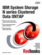
6. Also, you can see the status of iSCSI LIFs and working condition through the OnCommand System Manager as shown in Figure 22-5.
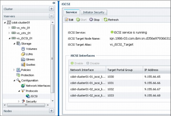
Figure 22-5 iSCSI Service status on OnCommand System Manager
Assigning aggregates as a resource for an SVM
In these steps, you can learn how to assign aggregates as a resource for a specific SVM to prioritize storage resource allocation to the highest-value workloads. Proceed as follows:
Figure 22-6 Editing iSCSI properties
2. Click the Resource Allocation tab when the Edit Vserver dialog box appears. You can select any specific aggregates for the current iSCSI SVM.
See Figure 22-7. This is a bad example for a configuration when choosing root aggregates.
Figure 22-7 Bad example: Assign a resource on the root aggregates
As you can see here, OnCommand System Manager warns against this kind of configuration. To prevent any future performance issues or reduced recovery time when the system is in HA condition and so on, you need to specify suitable data aggregates for your SVM.
3. If you specify any data aggregate that does not include a root aggregate, you will not see any warnings, as shown in Figure 22-8. This is a good example for a configuration.
Figure 22-8 Good example: Assign a resource on the data aggregates
22.2.2 Configuring a Windows 2008 Host for iSCSI
We have already checked the interoperability and configured iSCSI SVM on Clustered Data ONTAP. In these steps, we are going to configure the Windows 2008 iSCSI host.
Configuring iSCSI on the Windows 2008 host
On the Windows desktop, proceed as follows:
1. Open the Server Manager to activate an iSCSI feature, and select Add Features as follows. On the Server Manager, choose Action → Add Features. See Figure 22-9.
Figure 22-9 Add Features in Server Manager MMI

Figure 22-10 Selecting Multipath I/O
3. Then, to activate Multipath I/O, click the Install button. After clicking several following buttons, the Multipath I/O configuration will complete.
Installing FCP / iSCSI Windows Host Utilities
As we have already checked the suitable version for the host utilities, you must download the certified host utilities files from an IBM official site:
1. Use the following link to get N series software packages:
2. If you access the site with an authority, you can download the file as in Figure 22-11.

Figure 22-11 Windows FCP / iSCSI Windows Host Utilities download
3. The Windows Host Utilities enable you to connect a Windows host computer to the N series storage systems.
The Windows Host Utilities include an installation program that sets the required Windows registry and HBA values. Starting with version 5.3, the diagnostic programs for troubleshooting problems with Windows hosts connected to N series storage systems were replaced by the nSANity program. You can obtain the nSANity program from your technical support representative.
4. To install the FCP/iSCSI Windows Host Utilities, double-click the file downloaded from the IBM official site in Figure 22-11.
5. If your system has any issues regarding use of iSCSI with N series storage systems, you can see error messages as shown in Figure 22-12.
Figure 22-12 Host Utilities installation error due to Windows 2008 hotfix issues
As you can see here, the installation will not be able to complete due to some hotfix issues.
6. According to this description, the customer should install all of the hotfixes as mentioned.
|
Note: Here is a tip to download a hotfix. Just type the hotfix number at the end of the following link: http://support.microsoft.com/kb/
Example: For Q2528357, just visit the following Microsoft site:
Then you can request the hotfix you want.
|
a. After installing all of the hotfixes, you can complete the installation of FCP / iSCSI Windows Host Utilities.
Configuring the iSCSI software initiator in Windows 2008
In the following steps, you will configure the MPIO to use and manage iSCSI connections. We will not configure the Multiple Connections per Session (MCS) technique for multipathing. If you need more information about MCS, see the Microsoft MCS articles.
In order to check the current iSCSI configuration, proceed as follows:
1. Open the control panel and double-click iSCSI Initiator.
To make it easier to find the iSCSI initiator icon, you can select View by small icons
for viewing for the control panel.
for viewing for the control panel.
2. If an error message appears to indicate that the Microsoft ISCSI service is not running, click Yes to start the service. See Figure 22-13.

Figure 22-13 Starting Microsoft iSCSI
3. When the iSCSI Initiator Properties dialog box appears, click the Configuration tab as shown in Figure 22-14.

Figure 22-14 Configuration tab in iSCSI Initiator Properties
4. Record the name of the Initiator (IQN). In this picture, we can see that the IQN name is iqn.1991-05.com.microsoft:win-l02ldpmgpkp. We need this IQN name when we configure the iSCSI connection on the SVM in Clustered Data ONTAP.
5. To check the iSCSI Ethernet links that you made before in this chapter, click the Discovery tab. Click Discover Portal, enter the IP address of one of the ports within the iscsi_pset_1 port set, and click OK. See Figure 22-15.

Figure 22-15 Discover Target Portal
6. If you want to check the port set name or other information, you can use the cluster shell as well. See Example 22-2.
Example 22-2 The command of portset show
cdot-cluster01::> portset show
Vserver Portset Protocol Port Names Igroups
--------- ------------ -------- ----------------------- ------------
vs_iSCSI_01
iscsi_pset_1 iscsi cdot-cluster01-01_iscsi_lif_1, cdot-cluster01-01_iscsi_lif_2, cdot-cluster01-02_iscsi_lif_1, cdot-cluster01-02_iscsi_lif_2
-

Figure 22-16 Targets tab after specifying Target Portal Ip address
8. In order to proceed the next step, verify that the discovered target appears in the list and click Connect.
After clicking the Connect button, you can see the pop-up window shown in Figure 22-17.

Figure 22-17 Enabling multi-path settings
9. In this dialog box, select Enable multi-path and click Advanced.
10. .When you see the Advanced Settings dialog box in Figure 22-18, select the lowest target portal IP address, and click OK from the Target portal IP list.

Figure 22-18 Setting Target portal IP
11. Then click OK to close the Connect to Target dialog box and start a new iSCSI session between the initiator and target.
12. Check the current status of iSCSI on the Targets tab to see the link status change from inactive to connected.
You have just made one iSCSI connection between a Clustered Data ONTAP system and a Windows 2008 host. Now you need to create the remaining iSCSI paths between them.
13. Click Properties to begin creating additional sessions with all of the iSCSI LIFs within the port set. See Figure 22-19.

Figure 22-19 Properties dialog box
In the Properties dialog box, ensure that there is only one current session on the Session tab.
14. Click the Portal Groups tab and review all of the IPs, including the remaining three IPs that are currently available for sessions. See Figure 22-20.

Figure 22-20 iSCSI IP addresses in Portal Groups tab
15. After verifying all of the iSCSI IP addresses, click the Sessions tab again to add more sessions.
You can repeat the following steps three times to create four iSCSI sessions.
a. Click Add session.
Figure 22-21 Connect to Target
b. In the Advanced Settings dialog box, from the Target portal IP list, select the target portal IP address of one of the iSCSI LIFs that you have not assigned yet.
See Figure 22-22.
See Figure 22-22.
Figure 22-22 Advanced Settings
c. In the Properties dialog box, on the Sessions tab, verify that a new session has been created. See Figure 22-23.
Figure 22-23 Sessions properties
16. Repeat Steps 1-3 to create two more sessions, for a total four sessions, each with an iSCSI LIF in the port set of the target. See Figure 22-24.

Figure 22-24 Properties - iSCSI Sessions
You have now completed all of the iSCSI configuration. Your Windows 2008 machine is ready to use any iSCSI LUNs through the iSCSI connections.
22.2.3 Creating an iSCSI LUN
In the following steps, we will make a 100 MB LUN for Windows 2008 host. You can create different types volumes instead of this kind of normal LUN which we are making here.
Before creating any LUN, keep in mind that when you create a volume, Data ONTAP automatically performs the following actions:
•Reserves 5% of the space for Snapshot copies
•Schedules Snapshot copies
|
Note: Use the following guidelines to create volumes that contain LUNs:
•Do not create any LUNs in the system’s root volume. Data ONTAP uses this volume to administer the storage system.
•Use a SAN volume to contain the LUN.
•Ensure that no other files or directories exist in the volume that contains the LUN.
|
In the OnCommand System Manager, proceed as follows:
1. Click several icons to make an iSCSI LUN. In our lab environment, the path is Vservers → Cluster Name(cdot-cluster01) → iSCSI SVM(vs_iSCSI_01) → Storage → LUNs.
See Figure 22-25.
See Figure 22-25.

Figure 22-25 iSCSI SVM LUNs
2. Click the Create button to open the Create LUN Wizard. You will see the next window after you click the Next button. See Figure 22-26.
Figure 22-26 General Properties
3. You can create LUNs for an existing aggregate, volume, or qtree when there is available free space. Also, you can create a LUN in an existing volume or create a new FlexVol volume for the LUN.
Here are some values you can enter in this panel:
– Name: Specify the name of the iSCSI LUN which you want to make.
– Type: The LUN multiprotocol type, or operating system type, specifies the operating system of the host accessing the LUN. It also determines the layout of data on the LUN, the geometry used to access that data, and the minimum and maximum size of the LUN.
In this step, we can select one of three Windows host types. There is Windows 2003 MBR, Windows 2003 GTP, and Windows 2008 or later. If your host operating system is Windows Server 2008 or later, both MBR and GPT partitioning methods are supported. But if you are using Windows Server 2003, check which partitioning method is supported.
In this step, we can select one of three Windows host types. There is Windows 2003 MBR, Windows 2003 GTP, and Windows 2008 or later. If your host operating system is Windows Server 2008 or later, both MBR and GPT partitioning methods are supported. But if you are using Windows Server 2003, check which partitioning method is supported.
|
Note: Not all Data ONTAP versions support all LUN multiprotocol types. To get the most up-to-date information, you should consult the Interoperability Matrix.
|
– Thin Provisioned: Specify whether thin provisioning is enabled.
4. In the next window, you can select an aggregate for this LUN. See Figure 22-27.

Figure 22-27 Selecting a aggregate for an iSCSI LUN
5. In this step, you can select an aggregate for the iSCSI LUN. You can assign any aggregate included in Clustered Data ONTAP. That means several Volumes and LUNs are located in each aggregate. To increase the performance of the specific LUNs such as this iSCSI LUN, you can select one of aggregates with low I/O workload.
You can also specify the volume or accept the default volume name. And click Next.
6. On the Initiators Mapping page, you will define at least one more initiator group to make a connection between the iSCSI LUN and iSCSI Host. See Figure 22-28.

Figure 22-28 Initiators Mapping
7. The next step is to create an iSCSI initiator group with the name of IQN in Windows 2008. Click Add Initiator Group button. You must specify the name of IQN which was made before in Windows 2008. See Figure 22-29.
Figure 22-29 Adding initiators with the IQN name
8. Going back to the General tab, specify the rest values for the iSCSI initiator group. See Figure 22-30.

Figure 22-30 General tab in a Initiator group setting
Here are the values that you will need to enter:
– Name: Specify an initiator group name you want.
– Operating system: Specify an operating system type.
|
Note: The operating system types is different than the previously selected OS type. This configuration is only for an iSCSI initiator group.
|
– Type: Specify the supported protocol for the group.
– Portset: Select the portset for the iSCSI connections.
|
Note: A port set is a collection of LIFs. If you do not bind those igroups to a port set, any initiator within an igroup can access any LUN mapped to that igroup through any LIF.
The way an initiator connects to a LUN is through an igroup. In the following example, initiator1 can access LUN1 through LIF1 and LIF2. Without a port set, initiator1 can access LUN1 over any LIF.
|
9. When you have completed specifying all of these values, click the Create button. Back at the Initiators Mapping page, verify that the new igroup has been added to the list. Also select the Map check box to the left of the igroup and click Next. See Figure 22-31.

Figure 22-31 Initiators Mapping finish
10. When the iSCSI LUN creation is done, you can see the following panel on the OnCommand System Manager. See Figure 22-32.
Figure 22-32 Checking iSCSI LUN status
All of iSCSI related activities have been done. Now we will check that the Windows 2008 host can see the iSCSI LUN correctly.
22.3 Accessing the iSCSI LUN on the Windows 2008 Host
Here are the final steps needed to access an iSCSI LUN from Windows 2008. This is a simple way to configure iSCSI mapping on the Windows host, so we will describe it briefly.
Checking whether an iSCSI LUN was recognized or not
We can easily check that a Windows host can access the iSCSI LUN:
Figure 22-33 Checking the output of Disk Management
2. If you do not see the LUN disk in the bottom section of the center pane, right-click the Disk Management node in the left pane and select Rescan Disks. See Figure 22-34.
Figure 22-34 Rescan Disks
Figure 22-35 Initialize Disk
4. Now you will see the panel in Figure 22-36 where you can select a partition style.
Figure 22-36 Initialize Disk-Selecting Partition Style
5. Then normally you can assign the iSCSI LUN as a simple volume and format the drive with one of file system formats you want to use.
6. After that, you can see the iSCSI LUN through Windows Explorer. See Figure 22-37.
Figure 22-37 Accessing the iSCSI LUN
22.4 Further information
More details on iSCSI implementation can be found in the following IBM support documents:
•OnCommand System Manager 3.0 Help for Use with Clustered Data ONTAP Guide, located at this website:
•Windows Host Utilities 6.0.2 Release Notes, located at this website:
•Fibre Channel and iSCSI Configuration Guide for the Data ONTAP 8.0 Release Family, located at this website:
..................Content has been hidden....................
You can't read the all page of ebook, please click here login for view all page.