


Remote management
This chapter introduces the remote management networks through Remote LAN Module (RLM) and Baseboard Management Controller (BMC). You can manage your storage system remotely by using a remote management device, which can be the Service Processor (SP), the Remote LAN Module (RLM), or the Baseboard Management Controller (BMC), depending on the storage system model.
The RLM is included in the following systems:
N5200, N5300, N5500, N5600
N6040, N6060, N6070
N7600, N7700, N7800, N7900
The BMC is included in the 20xx systems (N3300, N3400, N3600).
The SP is included in all other systems (N62xx, N7950T).
The Service Processor (SP) is a remote management device that is included in the N62xx and N7950T systems. It enables you to access, monitor, and troubleshoot the storage system remotely.
The Remote LAN Module (RLM) is a remote management card that is supported on the N6000 and N7000 systems. The RLM provides remote platform management capabilities, including remote access, monitoring, troubleshooting, logging, and alerting features.
The Baseboard Management Controller (BMC) is a remote management device that is built into the motherboard of the N3000 systems. It provides remote platform management capabilities, including remote access, monitoring, troubleshooting, logging, and alerting features.
The following topics are covered:
36.1 Remote LAN Module (RLM)
The RLM command line interface (CLI) commands enable you to remotely access and administer the storage system and diagnose error conditions. Also, the RLM extends AutoSupport capabilities by sending alerts and notifications through an AutoSupport message.
The RLM its a management card intended for remote Management of midrange and high-end N series systems.
|
Tip: Place the interface on a management VLAN or separate network from the user data access path.
|
The RLM stays operational regardless of the operating state of the storage system. It is powered by a standby voltage, which is available as long as the storage system has input power to at least one of the storage system’s power supplies. Therefore you can logon to the RLM card even if a system is unavailable.
The RLM has a single temperature sensor to detect ambient temperature around the RLM board. Data generated by this sensor is not used for any system or RLM environmental policies. It is only used as a reference point that might help you troubleshoot storage system issues. For example, it might help a remote system administrator determine if a system was shut down due to an extreme temperature change in the system.
The following diagram illustrates how you can access the storage system and the RLM (Figure 36-1).
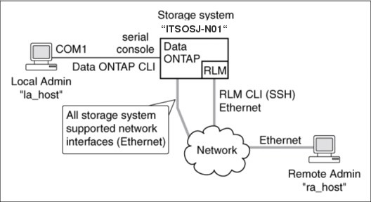
Figure 36-1 RLM diagram
Without the RLM, you can locally access the storage system through the serial console or from an Ethernet connection using any supported network interface. You use the Data ONTAP CLI to administer the storage system.
With the RLM, you can remotely access the storage system through the serial console. The RLM is directly connected to the storage system through the serial console. You use the Data ONTAP CLI to administer the storage system and the RLM.
With the RLM, you can also access the storage system through an Ethernet connection using a secure shell client application. You use the RLM CLI to monitor and troubleshoot the storage system.
If you have a data center configuration where management traffic and data traffic are on separate networks, you can configure the RLM on the management network.
The commands in the RLM CLI enable you to remotely access and administer the storage system and diagnose error conditions. Also, the RLM extends AutoSupport capabilities by sending alerts and notifications through an AutoSupport message.
Using the RLM CLI commands, you can perform the following tasks:
•Remotely administer the storage system by using the Data ONTAP CLI through the RLM’s system console redirection feature
•Remotely access the storage system and diagnose error conditions, even if the storage system has failed, by performing the following tasks:
– View the storage system console messages, captured in the RLM's console log
– View storage system events, captured in the RLM's system event log
– Initiate a storage system core dump
– Power-cycle the storage system (or turn it on or off)
– Reset the storage system
– Reboot the storage system
The RLM extends AutoSupport capabilities by sending alerts and “down system” or “down filer” notifications through an AutoSupport message when the storage system goes down, regardless of whether the storage system can send AutoSupport messages. Other than generating these messages on behalf of a system that is down, and attaching additional diagnostic information to AutoSupport messages, the RLM has no effect on the storage system’s AutoSupport functionality. The AutoSupport configuration settings and message content behavior of the RLM are inherited from Data ONTAP.
|
Tip: The RLM does not rely on the autosupport.support.transport option to send notifications. The RLM uses the Simple Mail Transport Protocol (SMTP).
|
In addition to AutoSupport messages, the RLM generates SNMP traps to configured trap hosts for all “down system” or “down filer” events, if SNMP is enabled for the RLM.
The RLM has a nonvolatile memory buffer that stores up to 4,000 system events in a system event log (SEL) to help you diagnose system issues. The event list from the SEL is automatically sent by the RLM to specified recipients in an AutoSupport message. The records contain the following data:
•Hardware events detected by the RLM, for example, system sensor status about power supplies, voltage, or other components
•Errors (generated by the storage system or the RLM) detected by the RLM, for example, a communication error, a fan failure, a memory or CPU error, or a “boot image not found” message
•Critical software events sent to the RLM by the storage system, for example, a system panic, a communication failure, an unexpected boot environment prompt, a boot failure, or a user triggered “down system” as a result of issuing the system reset or system power cycle command.
The RLM monitors the storage system console regardless of whether administrators are logged in or connected to the console. When storage system messages are sent to the console, the RLM stores them in the console log. The console log persists as long as the RLM has power from either of the storage system’s power supplies. Because the RLM operates with standby power, it remains available even when the storage system is power-cycled or turned off.
Hardware-assisted takeover is available on systems that support the RLM and have the RLM modules set up. For more information about hardware-assisted takeover, see the Data ONTAP 7- Mode High-Availability Configuration Guide.
The RLM supports the SSH protocol for CLI access from UNIX clients and PuTTY for CLI access from PC clients. Telnet and RSH are not supported by the RLM, and system options to enable or disable them have no effect on the RLM.
36.1.1 Ways to configure the RLM
Before using the RLM, you must configure it for your storage system and network. You can configure the RLM when setting up a new storage system with RLM already installed, after setting up a new storage system with RLM already installed, or when adding an RLM to an existing storage system.
You can configure the RLM by using one of the following methods:
•Initializing a storage system that has the RLM pre-installed:
When the storage system setup process is complete, the rlm setup command runs automatically. For more information about the entire setup process, see the Data ONTAP 7-Mode Software Setup Guide.
•Running the Data ONTAP setup script:
The setup script ends by initiating the rlm setup command.
•Running the Data ONTAP rlm setup command:
When the rlm setup script is initiated, you are prompted to enter network and mail host information.
In order to access the storage system through the RLM interface, an account must have login-sp capability. The storage system Administrators group has login-sp capability by default. If the root local account is disabled, then the naroot account is disabled and a local user with login-sp capability can log in to the RLM. It is available on the N62x0 and N7950Tplatforms.
|
Tip: Determine that the RLM firmware is version 4 or above.
|
In version 4 firmware, only ssh2 is enabled. The ssh protocol on the RLM is part of the RLM’s kernel operating system and therefore segmented for the implementation of ssh by the Data ONTAP operating system.
|
Action: Disable the root account and utilize accounts that are members of the storage systems Administrators group to manage the storage system through the RLM.
|
|
Tip: The RLM ignores the ssh.idle.timeout option and the console.timeout option. The settings for these options do not have any effect on the RLM.
|
|
Attention: RLM firmware 4.0 will track failed SSH login attempts from an IP address. If more than 5 repeated login failures are detected from an IP address in any 10-minute period, the RLM will stop all communication with that IP address for the next 15 minutes. Normal communication will resume after 15 minutes, but repeated login failures are detected again, communication will again be suspended for the next 15 minutes.
|
For detailed information about the RLM and its capabilities, see the “The Remote LAN Module” section of the Data ONTAP 8.0 7-Mode System Administration Guide.
36.1.2 Prerequisites for configuring the RLM
Before you configure the RLM, you must gather information about your network and your AutoSupport settings.
Here is the information you need to gather:
•Network information:
You can configure the RLM using DHCP or static addressing. If you are using an IPv4 address for the RLM, you need the following information:
– An available static IP address
– The netmask of your network
– The gateway of your network:
If you are using IPv6 for RLM static addressing, you need the following information:
If you are using IPv6 for RLM static addressing, you need the following information:
– The IPv6 global address
– The subnet prefix for the RLM
– The IPv6 gateway for the RLM
•AutoSupport information:
The RLM sends event notifications based on the following AutoSupport settings:
– autosupport.to
– autosupport.mailhost
It is best that you configure at least the autosupport.to option before configuring the RLM. Data ONTAP automatically sends AutoSupport configuration to the RLM, allowing the RLM to send alerts and notifications through an AutoSupport message to the system administrative recipients specified in the autosupport.to option. You are prompted to enter the name or the IP address of the AutoSupport mail host when you configure the RLM.x
36.1.3 Setting up the RLM
If you are running RLM firmware version 4.0 or later, and you have enabled IPv6 for Data ONTAP, you have the option to configure the RLM for only IPv4, for only IPv6, or for both IPv4 and IPv6. Disabling IPv6 on Data ONTAP also disables IPv6 on the RLM.
|
Attention: If you disable both IPv4 and IPv6, and if DHCP is also not configured, the RLM has no network connectivity.
|
Steps for setting up RLM
Follow these steps:
1. At the storage system prompt, enter one of the following commands:
setup
rlm setup
If you enter setup, the rlm setup script starts automatically after the setup command runs.
2. When the RLM setup asks you whether to configure the RLM, enter y.
3. Enter one of the following choices when the RLM setup asks you whether to enable DHCP on the RLM.
– To use DHCP addressing, enter y.
– To use static addressing, enter n.
|
Tip: DHCPv6 servers are not currently supported.
|
4. If you do not enable DHCP for the RLM, the RLM setup prompts you for static IP information.
Provide the following information when prompted:
– The IP address for the RLM:
|
Tip: Entering 0.0.0.0 for the static IP address disables IPv4 for the RLM.
|
– The netmask for the RLM
– The IP address for the RLM gateway
– The name or IP address of the mail host to use for AutoSupport
5. If you enabled IPv6 for Data ONTAP, and your RLM firmware version is 4.0 or later, the RLM supports IPv6. In this case, the RLM setup asks you whether to configure IPv6 connections for the RLM. Enter one of the following choices:
– To configure IPv6 connections for the RLM, enter y.
|
Tip: You can use the rlm status command to find the RLM version information.
|
– The subnet prefix for the RLM
– The IPv6 gateway for the RLM
|
Tip: You cannot use the RLM setup to enable or disable the IPv6 router-advertised address for the RLM. However, when you use the ip.v6.ra_enable option to enable or disable the IPv6 router-advertised address for Data ONTAP, the same configuration applies to the RLM.
|
For information about enabling IPv6 for Data ONTAP or information about global, link-local, and router-advertised addresses, see the Data ONTAP 7-Mode Network Management Guide.
6. At the storage system prompt, enter the following command to verify that the RLM network configuration is correct:
rlm status
7. At the storage system prompt, enter the following command to verify that the RLM AutoSupport function is working properly:
rlm test autosupport
|
Tip: The RLM uses the same mail host information that Data ONTAP uses for AutoSupport.
|
The following message is a sample of the output that Data ONTAP displays:
Sending email messages via SMTP server at [email protected]. If autosupport.enable is on, then each email address in autosupport.to should receive the test message shortly.
Connecting to the storage system console from the RLM
The RLM's system console command enables you to log in to the storage system from the RLM.
Follow these steps:
1. Enter the following command at the RLM prompt:
system console
The message “Type Ctrl-D to exit” appears.
2. Press Enter to see the storage system prompt.
You use Ctrl-D to exit from the storage system console and return to the RLM CLI.
The storage system prompt appears, and you can enter Data ONTAP commands.
Using online help at the RLM CLI
The RLM online help displays all RLM commands and options when you enter the question mark (?) or help at the RLM prompt.
Follow these steps:
1. To display help information for RLM commands, enter one of the following choices at the RLM prompt:
help
?
Example 36-1 shows the RLM CLI online help.
Example 36-1 RLM - Help
RLM-itsosj-n01> help
date - print date and time
exit - exit from the RLM command line interface
events - print system events and event information
help - print command help
priv - show and set user mode
rlm - commands to control the RLM
rsa - commands for Remote Support Agent
system - commands to control the system
version - print RLM version
Power cycle the N series through RLM
Turn the storage system on or off, or perform a power cycle (which turns system power off and then back on)
system power {on | off | cycle}
|
Tip: Standby power stays on, even when the storage system is off. During power-cycling, a brief pause occurs before power is turned back on.
|
|
Attention: Using the system power command to turn off or power-cycle the storage system might cause an improper shutdown of the system (also called a dirty shutdown) and is not a substitute for a graceful shutdown using the Data ONTAP halt command.
|
Display status for each power supply, such as presence, input power, and output power:
system power status
36.2 Baseboard Management Controller (BMC)
The Baseboard Management Controller (BMC) is a remote management device that is built into the motherboard of N3x00 storage systems. It provides remote platform management capabilities, including remote access, monitoring, troubleshooting, logging, and alerting features.
The Baseboard Management Controller (BMC) is a remote management device that is built into the motherboard of the N3x00 systems. It provides remote platform management capabilities, including remote access, monitoring, troubleshooting, logging, and alerting features.
The BMC stays operational regardless of the operating state of the system. Both the BMC and its dedicated Ethernet NIC use a standby voltage for high availability. The BMC is available as long as the system has input power to at least one of the system’s power supplies.
The BMC monitors environmental sensors, including sensors for the temperature of the system's nonvolatile memory (NVMEM) battery, motherboard, and CPU, and for the system's voltage level. When an environmental sensor has reached a critically low or critically high state, the BMC generates AutoSupport messages and shuts down the storage system. The data generated by the sensors can be used as a reference point to help you troubleshoot storage system issues. For example, it can help a remote system administrator determine if a system was shut down due to an extreme temperature change in the system.
The BMC also monitors non-environmental sensors for the status of the BIOS, power, CPU, and serial-attached SCSI (SAS) disks. These sensors are recorded by the BMC to assist support personnel.
You use the BMC sensors show command to display the ID and the current state of the sensors monitored by the BMC, and you use the BMC sensors search command to display information of a sensor by its ID.
Figure 36-2 illustrates how you can access the storage system and the BMC.
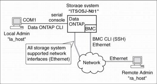
Figure 36-2 BMC diagram
With the BMC, you can access the storage system in these ways:
•Through an Ethernet connection using a secure shell client application:
You use the BMC CLI to monitor and troubleshoot the storage system.
You use the BMC CLI to monitor and troubleshoot the storage system.
•Through the serial console:
You use the Data ONTAP CLI to administer the storage system and the BMC.
You use the Data ONTAP CLI to administer the storage system and the BMC.
If you have a data center configuration where management traffic and data traffic are on separate networks, you can configure the BMC on the management network.
The commands in the BMC CLI enable you to remotely access and administer the storage system and diagnose error conditions. Also, the BMC extends AutoSupport capabilities by sending alerts and notifications through an AutoSupport message.
The BMC provides the following remote management capabilities for the storage system. You use the BMC CLI commands to perform the following tasks:
•Administer the storage system using the Data ONTAP CLI by using the BMC’s system console redirection feature
•Access the storage system and diagnose error conditions, even if the storage system has failed, by performing the following tasks:
– View the storage system console messages, captured in the BMC's system console log
– View storage system events, captured in the BMC's system event log
– Initiate a storage system core dump
– Power-cycle the storage system (or turn it on or off)
For instance, when a temperature sensor becomes critically high or low, Data ONTAP triggers the BMC to shut down the motherboard gracefully. The system console becomes unresponsive, but you can still press Ctrl-G on the console to access the BMC CLI. You can then use the system power on or system power cycle command from the BMC to power on or power cycle the system.
For instance, when a temperature sensor becomes critically high or low, Data ONTAP triggers the BMC to shut down the motherboard gracefully. The system console becomes unresponsive, but you can still press Ctrl-G on the console to access the BMC CLI. You can then use the system power on or system power cycle command from the BMC to power on or power cycle the system.
•Monitor environmental and non-environmental sensors for the controller module and the NVMEM battery.
You can switch between the primary and the backup firmware hubs to assist in bootup and recovery from a corrupted image in the storage system’s primary firmware hub.
The BMC extends AutoSupport capabilities by sending alerts and “down system” or “down filer” notifications through an AutoSupport message when the storage system goes down, regardless of whether the storage system can send AutoSupport messages. Other than generating these messages on behalf of a system that is down, and attaching additional diagnostic information to AutoSupport messages, the BMC has no effect on the storage system’s AutoSupport functionality. The system’s AutoSupport behavior is the same as it would be without BMC installed. The AutoSupport configuration settings and message content behavior of the BMC are inherited from Data ONTAP.
|
Tip: The BMC does not rely on the autosupport.support.transport option to send notifications. The BMC uses the Simple Mail Transport Protocol (SMTP).
|
The BMC has a nonvolatile memory buffer that stores up to 512 system events in a system event log (SEL) to help you diagnose system issues. The records contain the following data:
•Hardware events detected by the BMC, for example, system sensor status about power supplies, voltage, or other components
•Errors (generated by the storage system or the BMC) detected by the BMC, for example, a communication error, a fan failure, a memory or CPU error, or a “boot image not found” message
•Critical software events sent to the BMC by the storage system, for example, a system panic, a communication failure, an unexpected boot environment prompt, a boot failure, or a user triggered “down system” as a result of issuing the system reset or system power cycle command.
The BMC monitors the storage system console regardless of whether administrators are logged in or connected to the console. When storage system messages are sent to the console, the BMC stores them in the system console log. The system console log persists as long as the BMC has power from either of the storage system’s power supplies. Because the BMC operates with standby power, it remains available even when the storage system is power-cycled or turned off.
36.2.1 Ways to configure the BMC
Before using the BMC, you must configure it for your storage system and network. You can configure the BMC when setting up a new storage system with BMC already installed or after setting up a new storage system with BMC already installed.
You can configure the BMC by using one of the following methods:
•Initializing a storage system that has the BMC:
When the storage system setup process is complete, the bmc setup command runs automatically. For more information about the entire setup process, see the Data ONTAP 7-Mode Software Setup Guide.
•Running the Data ONTAP setup script:
The setup script ends by initiating the bmc setup command.
•Running the Data ONTAP bmc setup command:
When the bmc setup script is initiated, you are prompted to enter network and mail host information.
The BMC supports the SSH protocol for CLI access from UNIX clients and PuTTY for CLI access from PC clients. Telnet and RSH are not supported on the BMC, and system options to enable or disable them have no effect on the BMC.
|
Tip: The BMC ignores the ssh.idle.timeout option and the console.timeout option. The settings for these options do not have any effect on the BMC.
|
You can use root, naroot or Administrator to log into the BMC. These users have access to all commands available on the BMC. The password for all three account names is the same as the Data ONTAP root password. You cannot add additional users to the BMC.
|
Tip: The BMC uses the Data ONTAP root password (even if the root account is disabled) to allow access over the LAN with SSH. To access the BMC via SSH, you must configure the Data ONTAP root password. BMC accepts passwords that are no more than 16 characters.
|
|
Action: Take great care when using the BMC Management Port on the storage system. Set a strong password on the root account, disable the root account, and reset the root password on a regular basis.
|
For detailed information about the BMC and its capabilities, see the “The Baseboard Management Controller” section of the Data ONTAP 8.0 7-Mode System Administration Guide.
36.2.2 Prerequisites for configuring the BMC
Before you configure the BMC, you need to gather information about your network and your AutoSupport settings.
You need to gather the following information:
•Network information:
You can configure the BMC using DHCP or static addressing.
•If you are using DHCP addressing, you need the BMC’s MAC address.
|
Tip: If you do not provide a valid BMC MAC address, an EMS message shows up to remind you during system bootup or when you use the bmc status or the setup command.
|
•If you are using a static IP address, you need the following information:
– An available static IP address
– The netmask of your network
– The gateway of your network
•AutoSupport settings
The BMC sends event notifications based on the following Data ONTAP AutoSupport settings:
– autosupport.to
– autosupport.mailhost
It is best to configure at least the autosupport.to option before configuring the BMC. Data ONTAP automatically sends AutoSupport configuration to the BMC, allowing the BMC to send alerts and notifications through an AutoSupport message to the system administrative recipients specified in the autosupport.to option. You are prompted to enter the name or the IP address of the AutoSupport mail host when you configure the BMC.
36.2.3 Setting up the BMC
You can use the setup command or the bmc setup command to configure the BMC.
Before you begin, it is best to configure AutoSupport before configuring the BMC. Data ONTAP automatically sends AutoSupport configuration to the BMC, enabling the BMC to send alerts and notifications through an AutoSupport message.
Steps for setting up the BMC
Follow these steps:
1. At the storage system prompt, enter one of the following commands:
setup
bmc setup
If you enter setup, the bmc setup script starts automatically after the setup command runs.
2. When the BMC setup asks you whether to configure the BMC, enter y.
3. Enter one of the following choices when the BMC setup asks you whether to enable DHCP on the BMC:
– To use DHCP addressing, enter y.
– To use static addressing, enter n.
|
Tip: DHCPv6 servers are not currently supported.
|
4. If you do not enable DHCP for the BMC, the BMC setup prompts you for static IP information. Provide the following information when prompted:
– The IP address for the BMC
– The netmask for the BMC
– The IP address for the BMC gateway
– The name or IP address of the mail host to use for AutoSupport
|
Tip: Currently, you can use only IPv4 addresses to connect to the BMC.
|
5. Enter the Address Resolution Protocol (ARP) interval for the BMC when you are prompted.
6. If the BMC setup prompts you to reboot the system, enter the following command at the storage system prompt:
reboot
7. At the storage system prompt, enter the following command to verify that the BMC’s network configuration is correct:
bmc status
8. At the storage system prompt, enter the following command to verify that the BMC AutoSupport function is working properly:
bmc test autosupport
|
Tip: The BMC uses the same mail host information that Data ONTAP uses for AutoSupport. The bmc test autosupport command requires that you set up the autosupport.to option properly.
|
You have successfully set up the BMC AutoSupport function when the system displays the following output:
Please check ASUP message on your recipient mailbox.
Connecting to the storage system console from the BMC
You can access the BMC CLI from a console session by pressing Ctrl-G.
Press Ctrl-G at the storage system prompt to access the BMC CLI.
|
Tip: Entering system console at the BMC prompt returns you to the console session.
|
Only one administrator can log in to an active BMC CLI session at a time. However, the BMC allows you to open both a BMC CLI session and a separate, BMC-redirected system console session simultaneously.
When you use the BMC CLI to start a system console session, the BMC CLI is suspended, and the system console session is started. When you exit the system console session, the BMC CLI session resumes.
The BMC prompt is displayed as bmc shell ->.
Using online help at the BMC CLI
The BMC help displays all the available BMC commands when you enter the question mark (?) or help at the BMC prompt.
Example 36-2 shows the BMC CLI help.
Example 36-2 BMC online help
bmc shell -> ?
exit
bmc config
bmc config autoneg [enabled|disabled]
bmc config dhcp [on|off]
bmc config duplex [full|half]
bmc config gateway [gateway]
...
If a command has sub-commands, you can see them by entering the command name after the help command, as shown in Example 36-3).
Example 36-3 BMC help events
bmc shell -> help events
events all Print all system events
events info Print SEL(system event log)
information
events latest [N] Print N latest system events
events oldest [N] Print N oldest system events
events search [attr=N] Search for events by
attribute/value pair
events show [N] Print event N
Power cycle the N series through BMC
Turn the storage system on or off, perform a power cycle (which turns system power off and then back on), or display the power status:
system power {on | off | cycle | status}
|
Tip: Standby power stays on, even when the storage system is off. During power-cycling, there is a brief pause before power is turned back on.
|
|
Attention: Using the system power command to turn off or power-cycle the storage system might cause an improper shutdown of the system (also called a dirty shutdown) and is not a substitute for a graceful shutdown using the Data ONTAP halt command.
|
36.3 Service Processor (SP)
The Service Processor (SP) command line interface (CLI) commands enable you to remotely access and administer the storage system and diagnose error conditions. Also, the SP extends AutoSupport capabilities by sending alerts and notifications through an AutoSupport message.
The SP provides the following capabilities:
•The SP enables you to access the storage system remotely to diagnose, shut down, power-cycle, or reboot the system, regardless of the state of the storage controller.
The SP is powered by a standby voltage, which is available as long as the system has input power to at least one of the system’s power supplies.
The SP is powered by a standby voltage, which is available as long as the system has input power to at least one of the system’s power supplies.
The SP is connected to the system through the serial console. You can log in to the SP by using a Secure Shell client application from an administration host. You can then use the SP CLI to monitor and troubleshoot the system remotely. In addition, you can use the SP to access the system console and run Data ONTAP commands remotely.
You can access the SP from the system console or access the system console from the SP. The SP allows you to open both an SP CLI session and a separate system console session simultaneously.
For instance, when a temperature sensor becomes critically high or low, Data ONTAP triggers the SP to shut down the motherboard gracefully. The system console becomes unresponsive, but you can still press Ctrl-G on the console to access the SP CLI. You can then use the system power on or system power cycle command from the SP to power on or power cycle the system.
•The SP monitors environmental sensors and logs system events to help you take timely and effective service actions in the event that a system problem occurs.
The SP monitors the system temperatures, voltages, currents, and fan speeds. When an environmental sensor has reached an abnormal condition, the SP logs the abnormal readings, notifies Data ONTAP of the issue, and sends alerts and “down system” notifications as necessary through an AutoSupport message, regardless of whether the storage system can send AutoSupport messages.
Other than generating these messages on behalf of a system that is down and attaching additional diagnostic information to AutoSupport messages, the SP has no effect on the storage system’s AutoSupport functionality. The AutoSupport configuration settings and message content behavior are inherited from Data ONTAP.
|
Tip: The SP does not rely on the autosupport.support.transport option to send notifications. The SP uses the Simple Mail Transport Protocol (SMTP).
|
If SNMP is enabled for the SP, the SP generates SNMP traps to configured trap hosts for all “down system” events.
The SP also logs system events such as boot progress, Field Replaceable Unit (FRU) changes, Data ONTAP-generated events, and SP command history.
•The SP has a nonvolatile memory buffer that stores up to 4,000 system events in a system event log (SEL) to help you diagnose system issues.
The SEL stores each audit log entry as an audit event. It is stored in onboard flash memory on the SP. The event list from the SEL is automatically sent by the SP to specified recipients through an AutoSupport message.
The SEL contains the following data:
– Hardware events detected by the SP, for example, system sensor status about power supplies, voltage, or other components
– Errors detected by the SP, for example, a communication error, a fan failure, or a memory or CPU error
– Critical software events sent to the SP by the storage system, for example, a system panic, a communication failure, a boot failure, or a user-triggered “down system” as a result of issuing the SP system reset or system power cycle command
•The SP monitors the system console regardless of whether administrators are logged in or connected to the console.
When system messages are sent to the console, the SP stores them in the console log. The console log persists as long as the SP has power from either of the storage system’s power supplies. Because the SP operates with standby power, it remains available even when the storage system is power cycled or turned off.
•Hardware-assisted takeover is available on systems that support the SP and have the SP configured.
For more information about hardware-assisted takeover, see the Data ONTAP 7-Mode High-Availability Configuration Guide.
Figure 36-3 illustrates access to the storage system and the SP.
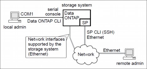
Figure 36-3 Service Processor diagram
36.3.1 Ways to configure the SP
Configuring the SP for your storage system and network enables you to log in to the SP over the network. It also enables the SP to send an AutoSupport message in the event of a problem. You can configure the SP when you set up a new storage system. You can also configure the SP by running the setup or the sp setup command.
On a storage system that comes with the SP, you can configure the SP by using one of the following methods:
•Initializing a new storage system:
When you power on a storage system for the first time, the setup command begins to run automatically. When the storage system setup process is complete, the sp setup command runs automatically and prompts you for SP configuration information. For more information about the system setup process, see the Data ONTAP 7-Mode Software Setup Guide.
•Running the Data ONTAP setup command:
If you want to change both system setup and SP configuration, you use the setup command. The system setup process ends by initiating the sp setup command.
•Running the Data ONTAP sp setup command directly:
If the storage system has been set up and you want to reconfigure only the SP, you can use the sp setup command, which omits system setup and prompts you directly for SP configuration information.
In order to access the storage system through the SP interface an account must have login-sp capability. The storage system Administrators group has login-sp capability by default. If the root local account is disabled, then the naroot account is disabled and a local user with login-sp capability can log in to the SP.
SP firmware 1.2 and later will track failed SSH login attempts from an IP address. If more than 5 repeated login failures are detected from an IP address in any 10-minute period, the RLM will stop all communication with that IP address for the next 15 minutes. Normal communication will resume after 15 minutes, but, if repeated login failures are detected again, communication will again be suspended for the next 15 minutes.
For detailed information about the SP and its capabilities, see the “Using the service processor for remote system management” section of the Data ONTAP 8.1 7-Mode System Administration Guide.
36.3.2 Prerequisites for configuring the SP
You need the following information about your network and AutoSupport settings when you configure the SP:
•Network information:
If you are using an IPv4 address for the SP, you need the following information:
– An available static IP address for the SP
– The netmask of your network
– The gateway IP of your network
If you are using IPv6 for SP static addressing, you need the following information:
– The IPv6 global address
– The subnet prefix for the SP
– The IPv6 gateway IP for the SP
For information about network interfaces and management, see the Data ONTAP 7-Mode Network Management Guide.
•AutoSupport information:
The SP sends event notifications based on the settings of the following AutoSupport options:
– autosupport.to
– autosupport.mailhost
At the minimum, consider configuring the autosupport.to option before configuring the SP. Data ONTAP automatically sends AutoSupport configuration to the SP, allowing the SP to send alerts and notifications through an AutoSupport message to the system administrative recipients specified in the autosupport.to option. You are prompted to enter the name or the IP address of the AutoSupport mail host when you configure the SP.
36.3.3 Setting up the SP
You can use the setup command or the sp setup command to configure the SP, depending on whether you want to change the system setup besides configuring the SP. You can configure the SP to use either a static or a DHCP address.
If you have enabled IPv6 for Data ONTAP, you have the option to configure the SP for only IPv4, for only IPv6, or for both IPv4 and IPv6. Disabling IPv6 on Data ONTAP also disables IPv6 on the SP. If you disable both IPv4 and IPv6, and if DHCP is also not configured, the SP will not have network connectivity.
The firewall for IPv6 is configured to accept a maximum of 10 Internet Control Message Protocol (ICMP) packets in a one-second interval. If your system has management software that frequently performs diagnostic checks, this limit can cause false positive errors to be generated. Consider increasing the software's ping interval or tuning the software's report to expect the false positive errors caused by the ICMP limit.
Steps for setting up the SP
Follow these steps:
1. At the storage system prompt, enter one of the following commands:
– setup
If you want to change both system setup and SP configuration, you use the setup command. When the storage system setup process is complete, the sp setup command runs automatically and prompts you for SP configuration information.
For information about system setup, see the Data ONTAP 7-Mode Software Setup Guide.
– sp setup
If the storage system has been set up and you want to configure only the SP, you use the sp setup command, which omits system setup and prompts you directly for SP configuration information.
2. When the SP setup asks you whether to configure the SP, enter y.
3. Enter one of the following choices when the SP setup asks you whether to enable DHCP on the SP:
– To use DHCP addressing, enter y.
|
Tip: The SP supports DHCPv4 but not DHCPv6.
|
– To use static addressing, enter n.
4. If you do not enable DHCP for the SP, provide the following static IP information when the SP setup prompts you to enter it:
– The IP address for the SP
|
Tip: Entering 0.0.0.0 for the static IP address disables IPv4 for the SP. If you enter 0.0.0.0 for the static IP address, you must enter 0.0.0.0 also for the netmask and the IP address for the SP gateway.
|
– The netmask for the SP
– The IP address for the SP gateway
– The name or IP address of the mail host to use for AutoSupport
5. If you have enabled IPv6 for Data ONTAP, the SP supports IPv6. In this case, the SP setup asks you whether to configure IPv6 connections for the SP. Enter one of the following choices:
– To configure IPv6 connections for the SP, enter y.
– To disable IPv6 connections for the SP, enter n.
6. If you choose to configure IPv6 for the SP, provide the following IPv6 information when the SP setup prompts you to enter it:
– The IPv6 global address:
Even if no IPv6 global address is assigned for the SP, the link-local address is present on the SP. The IPv6 router-advertised address is also present if the ip.v6.ra_enable option is set to on.
– The subnet prefix for the SP
– The IPv6 gateway for the SP
|
Tip: You cannot use the SP setup to enable or disable the IPv6 router-advertised address for the SP. However, when you use the ip.v6.ra_enable option to enable or disable the IPv6 router-advertised address for Data ONTAP, the same configuration applies to the SP
|
For information about enabling IPv6 for Data ONTAP or information about global, link-local, and router-advertised addresses, see the Data ONTAP 7-Mode Network Management Guide.
7. At the storage system prompt, enter the following command to verify that the SP network configuration is correct:
sp status
8. At the storage system prompt, enter the following command to verify that the SP AutoSupport function is working properly:
sp test autosupport
|
Tip: The SP uses the same mail host information that Data ONTAP uses for AutoSupport.
|
The following message is a sample of the output Data ONTAP displays:
Sending email messages via SMTP server at [email protected]. If autosupport.enable is on, then each email address in autosupport.to should receive the test message shortly.
Accessing the SP from the system console
You can access the SP from the system console to perform monitoring or troubleshooting tasks.
To access the SP CLI from the system console, press Ctrl-G at the storage system prompt. The SP prompt appears, indicating that you have access to the SP CLI.
|
Tip: You can press Ctrl-D and then press Enter to return to the system console.
|
Only one administrator can log in to an active SP CLI session at a time. However, the SP allows you to open both an SP CLI session and a separate system console session simultaneously.
The SP prompt appears with SP in front of the hostname of the storage system. For example, if your storage system is named itsosj-n01, the storage system prompt is itsosj-n01> and the prompt for the SP session is SP itsosj-n01>.
If an SP CLI session is currently open, you or another administrator with privileges to log in to the SP can close the SP CLI session and open a new one. This feature is convenient if you logged in to the SP from one computer and forgot to close the session before moving to another computer, or if another administrator takes over the administration tasks from a different computer.
You can use the SP's system console command to connect to the storage system console from the SP. You can then start a separate SSH session for the SP CLI, leaving the system console session active. When you press Ctrl-D to exit from the storage system console, you automatically return to the SP CLI session. If an SP CLI session already exists, the following message appears:
User username has an active console session.
Would you like to disconnect that session, and start yours [y/n]?
Would you like to disconnect that session, and start yours [y/n]?
If you enter y, the session owned by username is disconnected and your session is initiated. This action is recorded in the SP’s system event log.
Using online help at the SP CLI
The SP online help displays the SP CLI commands and options when you enter the question mark (?) or help at the SP prompt.
1. To display help information for the SP commands, enter one of the following at the SP prompt:
help
?
Example 36-4 shows the SP CLI online help.
Example 36-4 SP help
SP itsosj-n01> help
date - print date and time
exit - exit from the SP command line interface
events - print system events and event information
help - print command help
priv - show and set user mode
sp - commands to control the SP
rsa - commands for Remote Support Agent
system - commands to control the system
version - print SP version
2. To display help information for the option of an SP command, enter the following command at the SP prompt:
help SP_command
Example 36-5 shows the SP CLI online help for the SP events command.
Example 36-5 SP help events
SP itsosj-n01> help events
events all - print all system events
events info - print system event log information
events newest - print newest system events
events oldest - print oldest system events
events search - search for and print system events
Power cycle the N series through SP
Turn the storage system on or off, or perform a power cycle (turning system power off and then back on):
system power{on|off|cycle}
|
Tip: The standby power stays on to keep the SP running without interruption. During the power cycle, a brief pause occurs before power is turned back on.
|
|
Attention: Using the system power command to turn off or power-cycle the storage system might cause an improper shutdown of the system (also called a dirty shutdown) and is not a substitute for a graceful shutdown using the Data ONTAP halt command
|
36.4 CLI administration
In this section, we introduce various ways to administer N series systems through CLI (command line interface). We cover the following network protocols:
•telnet
•SSH
•RSH
•Audit Logging
On storage systems shipped with Data ONTAP 8.0 or later, secure protocols are enabled and non-secure protocols are disabled by default. SecureAdmin is set up automatically on storage systems shipped with Data ONTAP 8.0 or later. These systems have the following default security settings:
•Secure protocols (including SSH, SSL, and HTTPS) are enabled by default.
•Non-secure protocols (including RSH, Telnet, FTP, and HTTP) are disabled by default.
We advise that you configure and enable SecureAdmin. immediately after initially setting up Data ONTAP. This preferred practice enables SSH and SSL encryption for secure administration of the N series storage system. Also, use only the SSH version 2 protocol and using SSH public key authentication. For more information about SecureAdmin, see the Data ONTAP System Administration Guide.
Although SSH version 1 is supported in Data ONTAP, it has known exploitable vulnerabilities that can be prevented only by using SSH version 2 exclusively. SSH public keys provide a stronger and more granular method of SSH access to N series storage systems.
In Data ONTAP version 7.3.4 the option to disable sslv2 (options ssl.v2.enable off) was added.
Audit logging
An audit log is a record of commands executed at the console through a telnet shell or an SSH shell or by using the rsh command. All the commands executed in a source file script are also recorded in the audit log. Administrative HTTP operations, such as those resulting from the use of System Manager or another SDK ONTAPIR application, are logged. All login attempts to access the storage system, with success or failure, are also audit logged.
In addition, changes made to configuration and registry files are audited. Read-only APIs by default are not audited but you can enable auditing with the auditlog.readonly_api.enable option. By default, Data ONTAP is configured to save an audit log. The audit log data is stored in the /etc/log directory in a file called auditlog. For configuration changes, the audit log shows the following information:
•Which configuration files were accessed
•When the configuration files were accessed
•What was changed in the configuration files
For commands executed through the console, a telnet shell, or an SSH shell or by using the rsh command, the audit log shows the following information:
•Which commands were executed
•Who executed the commands
•When the commands were executed
You can access the audit log files using your NFS or CIFS client, or HTTP(s).
For detailed information about audit logging and its capabilities, see the “Audit logging” section of the Data ONTAP 8.x 7-Mode System Administration Guide.
|
Tip: There is no option to extend the maximum audit log entry character limit. The limit is 511 characters.
|
Preferred practice
Audit logging must always be enabled. This logs administrative access from the console and from remote shell sessions. Log file size depends on corporate security policy, but it must be large enough to record several days' worth of administrative usage at a minimum. A preferred practice is to set log file size to a large value (several megabytes, at least) and then adjust the size after monitoring growth of the log file.
Some corporate security policies might dictate central log collection and analysis. Data ONTAP does support the sending of Data ONTAP audit logs to an external syslog host. Although we do not advise using an external syslog as a preferred practice, consider this option as a way to collect historical data; see syslog.conf for details.
..................Content has been hidden....................
You can't read the all page of ebook, please click here login for view all page.