


IBM TS7700 parameter examples
This appendix explains two different parameter scenarios. The first parameter example shows how different definitions and parameters interact. The second example set shows how the tape partitions can be used to influence the configuration and performance.
|
Important: These examples are not leading practices or recommended configurations to be adopted. The purpose of this appendix is to demonstrate how some operational choices or parameter interactions can affect your TS7700 subsystem by walking you through some options and settings, and evaluating the effects of different settings or choices.
|
This appendix describes four examples of how consistency policies work and how certain parameters influence the behavior of the configurations. This appendix explains the usage of the following objects:
•Different Copy Consistency Policies
•Scratch allocation assistance (SAA) and device allocation assistance (DAA)
•Retain Copy Mode
•Override settings
•Synchronous deferred on Write Failure Option
•Cluster family
The examples are meant as a drill to exercise some setting options and evaluate the effects on the grid. They are only hypothetical implementations, for the sake of the settings exercise. Although the distance between data centers has an influence on latency, the distance has no influence on the function.
These examples show no Time Delay Replication copy policy. A Time Delay Replication copy is only made after a certain amount of time has expired (after creation / after last access). While the timer is not elapsed, this type of copy behaves regarding the dependencies to the parameter mentioned in these examples like a No copy. When the timer is elapsed, the copy behaves like a copy produced in Deferred mode copy. Therefore, no specific examples need to be added.
This appendix includes the following sections:
General example setup
This appendix explains the following examples:
•Two-cluster grid for high availability (HA) and disaster recovery (DR)
•Two-cluster grid for HA and DR with selected Copy Override Policies and Retain
Copy Mode
Copy Mode
•Three-cluster grid for HA and DR
•Four-cluster grid for HA and DR
•Four-cluster grid for HA and DR with cluster families
Every example includes the following Management Classes (MCs):
•MC1: Synchronous mode for object access method (OAM) object support and hierarchical storage management (HSM) Migration Level 2 (ML2) workload.
•MC2: At least two clusters, which are defined with Rewind Unload (RUN) for data that must be immediately copied to the DR site.
•MC3: Deferred for workload types, where a deferred copy can be considered.
•MC4: An MC that is limited to a specific cluster (No Copy for all other clusters). This MC is needed for Bulk Volume Information Retrieval (BVIR) and Copy Export runs.
The data in cache statement applies only to the condition when all clusters are available. In outages, the normal rules apply. Synchronous goes to synchronous deferred (if the synchronous write failure option is enabled), and RUN copies go to the Immediate-Deferred copy queue. As soon as the failing cluster is recovered and is available in the grid again, the copies are made according to their policies.
Each of the examples also shows one example of the specific influence of SAA, DAA, override policies, the synchronous write failure option, and the service preparation mode of a cluster. They also describe the copy policy behavior if a disaster occurs.
Without DAA, there is no pre-selection of the mount point for a non-scratch mount. This is addressed only in the four-cluster grid example.
The Tape Volume Cache (TVC) selection for scratch mounts depends on the Copy Consistency Policy. For non-scratch mounts, there is a general rule that if a cluster has a valid copy of the logical volume in cache, this cluster TVC is selected as the I/O TVC.
Table G-1 lists the influence of the features as explained in the following examples.
Table G-1 Features mapped to examples
|
Feature
|
Where to find
|
Comment
|
|
Scratch allocation assist (SAA)
|
Example 4
|
|
|
Device allocation assist for private volumes (DAA)
|
Example 1
|
|
|
Retain Copy Mode
|
Example 1
|
Only used in the MC MCD
|
|
Override settings: Prefer local cache for fast ready mounts
|
Example 2
|
|
|
Override settings: Prefer local cache for non-fast ready mounts
|
Example 2
|
|
|
Override settings: Force volumes to be mounted on this cluster in local cache
|
Example 2
|
|
|
Override settings: Copy Count Override
|
Example 3
|
|
|
Synchronous Deferred on Write Failure option
|
Example 1, 3, 4, 5: ON
Example 2: OFF
|
|
|
Cluster family
|
Example 4
|
|
Example 1: Two-cluster grid for HA and DR
With a two-cluster grid, you can configure the grid for disaster recovery (DR), high availability (HA), or both. Configuration considerations are described for two-cluster grids. The scenario that is presented is a typical configuration. Other configurations are possible and might be better suited for your environment.
Figure G-1 shows a homogeneous TS7740 cluster grid. You can also choose to introduce a TS7720 only, or a hybrid cluster. For more information about choosing the best configuration to meet your demands, see 2.4.1, “Homogeneous versus hybrid grid configuration” on page 103.

Figure G-1 Example of two-cluster grid for HA limited distance DR
Setting up the configuration
The environment of a two-cluster grid for HA and DR is listed in Table G-2.
Table G-2 Environment for a two-cluster grid for HA and DR
|
Fact
|
Number or state
|
Comment
|
|
Number of clusters
|
Two
|
Divided in two data centers.
|
|
Type of cluster
|
TS7740 homogeneous
|
|
|
Host connection
|
|
All hosts connected to all clusters.
|
|
SAA
|
Disabled
|
|
|
DAA for private volumes
|
Disabled
|
The default of DAA for private volume is enabled. The disablement is for educational purposes only.
|
|
Override settings
|
None
|
|
|
Synchronous Deferred on Write Failure option
|
On
|
|
|
Cluster family
|
None
|
|
Results of this parameter setting
MCA has a parameter setting of S/S:
•Data in cache: Data is written synchronously to both clusters.
•Mount behavior in normal conditions: Controlled by client (job entry subsystem 3 (JES3)/JES2).
•Mount behavior in outage conditions: If one of the clusters is unavailable, the mount is still performed on the remaining cluster. This happens because the Synchronous Deferred on Write Failure Option is set. The default is that this option is not selected. In this case, the mount will fail (see the next examples).
•TVC Selection for scratch mounts: Both clusters are treated equally regarding TVC selection.
MCB has a parameter setting of R/R:
•Data in cache: At RUN time, a valid copy is in cache at both locations.
•If one cluster is unavailable, the copies are set to immediate copy deferred and run as soon the cluster is available again.
•Mount behavior in normal conditions: Controlled by client (JES3/JES2).
•Mount behavior in outage conditions: If one cluster is unavailable, the mount is still run.
•TVC Selection for scratch mounts: Both clusters are treated equally regarding TVC selection.
MCC has a parameter setting of R/D:
•Data in cache: At RUN time, a valid copy is in one cache. The other cluster has no valid copy currently. The deferred copy is run later.
•Mount behavior in normal conditions: Controlled by client (JES3/JES2).
•Mount behavior in outage conditions: If one cluster is unavailable, the mount is still run.
•TVC Selection for scratch mounts: Cluster 0 is preferred for TVC selection. That means that if a mount is run in Cluster 1, the TVC from Cluster 0 will probably be selected. However, there are still some cases when the TVC from Cluster 1 will be selected (for non-scratch mounts or a heavy workload on Cluster 0).
MCD has parameters R/N and N/R:
•Data in cache: At RUN time, only one copy of data in the chosen cluster is available. No copy is run to the other cluster.
•All data that is stored by using this MC is in only one location. In a disaster, data loss is the result. Also, consider that a media failure can also result in data loss.
•Mount behavior in normal conditions: Controlled by client (JES3/JES2).
Mount behavior in outage conditions: If one cluster is unavailable, a scratch mount is still run. The MC from the mount cluster will be selected. This is always a RUN in this example. Retain Copy mode is only valid for non-scratch mounts.
|
Note: Because a copy is located only in one of the two clusters, private mounts might fail in an outage if the targeted volume is not in the cluster that remains available.
|
•TVC selection for scratch mounts: Local cache is selected.
|
These MCs are necessary for BVIR processing, DR volume testing, and Copy Export runs.
|
MCD with Retain Copy Mode
Assume that you have not specified Retain Copy Mode for this MC. The scratch mount was placed on Cluster 0, and the volume was created on Cluster 0 only (R,N). Now, you use this volume for several runs. Without DAA, the z/OS can select a virtual drive either from Cluster 0 or Cluster 1. If Cluster 1 is selected, the MC is again acknowledged (N,R), and a second copy of the volume is created. To avoid this, you can specify the Retain Copy Mode.
In this case, the origin MC (R,N) is selected, and no additional copy by a specific mount is created.
Effect of features on the grid behavior
SAA can be used in this example. However, the benefit is limited because both clusters are TS7740 and might present the same workload characteristics. If your TS7740s have different cache sizes or are differently connected to the host (performance), SAA might be considered to prefer a specific TS7740.
DAA for private volumes might be chosen to ensure that a cluster with a valid copy is selected. In this example, the benefits are limited. For MCs S/S, R/R, and R/D, there must always be a valid copy available in both clusters. Therefore, DAA made no difference. But the MCD example (RN/NR) benefits because a private mount is directed to the cluster that holds the valid copy.
Because this is a two-cluster grid, cluster families do not provide value in this configuration.
Special considerations for a consistency policy with “R,D” and “D,R”
[R,D] and [D,R] are used when the local cluster is meant to always be the I/O TVC. But, it might result in unexpected immediate copies during certain private mount operations, such as when the location of the R swaps. This can happen in a job execution when a volume is created in one cluster (R), and almost immediately, the next step of the execution mounts the same volume to the other cluster (swapping the R location).
It is better to use D/D with the preferred local for Fast Ready mounts, which eliminates any unexpected immediate copies from occurring.
Example 2: Two-cluster grid for HA and DR
Copy policies override settings and Retain Copy Mode. Example 2, as shown in Figure G-2, has the same configuration as shown in Example 1. However, several features are now applied.
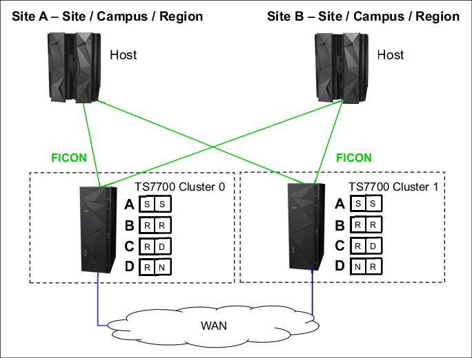
Figure G-2 Example of two-cluster grid for HA and limited distance DR
Setting up the configuration
The parameter settings are listed in Table G-3. These examples are for this exercise only and are not recommendations or preferred practices.
Table G-3 Environment for a two-cluster grid for HA and DR
|
Fact
|
Number/State
|
Comment
|
|
Number of clusters
|
Two
|
Divided in two data centers.
|
|
Type of cluster
|
TS7740 homogeneous
|
|
|
Host connection
|
|
All hosts connected to all clusters.
|
|
SAA
|
Disabled
|
|
|
DAA for private volumes
|
Disabled
|
|
|
Retain Copy Mode
|
Disabled
|
|
|
Override settings: Prefer local cache for fast ready mounts
|
On
|
Is set on both clusters.
|
|
Override settings: Prefer local cache for non-fast ready mounts
|
On
|
Is set only on Cluster 1.
|
|
Override settings: Force volumes to be mounted on this cluster in local cache
|
Off
|
This override setting overwrites the previous two, if turned on.
|
|
Override settings: Copy Count Override
|
Off
|
|
|
Synchronous Deferred on Write Failure option
|
Off
|
|
|
Cluster family
|
None
|
|
Results of this parameter setting
MCA has a parameter setting of S/S:
•Data in cache: Data is written synchronously to both clusters.
•Mount behavior in normal conditions: Controlled by customer (JES3/JES2).
•Mount behavior in outage conditions: The mount fails because the Synchronous Write Failure is set to OFF. This situation might occur in the following situations:
– Service preparation (microcode update or upgrades)
– Actual failure of one cluster
– Actual failure of all grid network links
– Real disaster situation
•Synchronous mode spells an absolute need of data protection. It is your choice to set Synchronous Deferred on Write Failure ON or OFF. When OFF, applications that use this MC must have both clusters available always, ruling out otherwise concurrent activities, such as microcode updates or upgrades in the equipment.
•With this flag ON (one cluster is temporarily unavailable), the application is still able to mount volumes to the remaining cluster. Copies are rolled back to Synchronous-Deferred mode, which is the highest priority of deferred copy queue. The composite library enters the Synchronous Deferred State, exiting from it only when all Synchronous-Deferred copies have been run in all distributed libraries of the grid.
•For TVC selection for scratch mounts, each cluster has a defined number of virtual drives. If a mount occurs, a virtual drive is selected. The Override policy for Fast Ready Categories ensures that the local TVC is selected. No remote mount occurs.
MCB has a parameter setting of R/R:
•Data in cache: At RUN time, a valid copy is in each cache.
•If one cluster is not available, the copies are set to immediate copy deferred and run as soon the cluster is available again.
•Mount behavior in normal conditions: Controlled by customer (JES3/JES2).
•Mount behavior in outage conditions: If one cluster is not available, the mount is still run.
•TVC selection for scratch mounts: As described in MCA, the local TVC is used. No remote mount occurs.
MCC has a parameter setting of R/D:
•Data in cache: At RUN time, a valid copy is in one cache, and the other cluster has no valid copy. The deferred copy is run later.
•Mount behavior in normal conditions: Controlled by customer (JES3/JES2).
•Mount behavior in outage conditions: If one cluster is not available, the mount is still run.
•TVC selection for scratch mounts: As described in MCA, the local TVC is used. No remote mount occurs.
MCD has parameter settings R/N and N/R:
•Data in cache: At RUN time, only one copy of data in the chosen cluster is available. No copy is run to the other cluster.
•Mount behavior: If the cluster is not available, the mount is still run.
|
Note: Because a copy is located only within one of the two clusters, private mounts might fail in an outage if the targeted volume is not in the cluster that remains available.
|
•TVC selection for scratch mounts: As described in MCA, the local TVC is used. No remote mount occurs.
|
Important: These MCs are necessary for BVIR processing, DR volume testing, and Copy Export runs.
|
Special considerations for non-Fast Ready mounts and Copy Policy Override
Assume that you have a private non-Fast Ready mount for a logical volume. MC C with R/D is selected. Prefer local cache for non-fast ready mounts is selected on Cluster 1, but not on Cluster 0.
If Cluster 0 is selected as the virtual drive mount point, the TVC might be selected where a valid copy exists. That can result in a remote write to Cluster 1, and the data will be in Cluster 1 after RUN. If the data was modified, a copy is processed to Cluster 0 at RUN time. If the data was not modified, no copy occurs.
If Cluster 1 is selected, it prefers to use the TVC of Cluster 1 because of the Copy Policy Override. If no valid copy of the logical volume exists in the cache of Cluster 1, a recall from a stacked volume occurs. After RUN, a valid copy will be in Cluster 1. If the data was modified, a copy is processed to Cluster 0 at RUN time. If the data was not modified, no copy occurs.
If Cluster 1 has no valid copy of the data (in cache or on a stacked volume), Cluster 0 is selected for TVC.
Special considerations: “Force volumes to be mounted on this cluster in local cache”
This override policy is valid for all mounts. It forces the selected I/O cluster to use the local TVC. If, for any reason, the virtual node (vNode) cluster is unable to act as the I/O Tape Volume Cache (TVC), a mount operation fails even if remote TVC choices are still available when this override is enabled.
Example 3: Three-cluster grid for HA and DR
Assume that two or three TS7700 clusters are in separate locations and are separated by a distance dictated by your company’s requirements for DR. In a three-cluster grid configuration, DR and HA can also be achieved simultaneously by ensuring that two local, high-availability clusters possess volume copies and have shared access to the host, and the third and remote cluster possesses deferred volume copies for DR.
During a stand-alone cluster outage, the three-cluster grid solution maintains no single points of failure that prevent you from accessing your data, assuming that copies exist on other clusters as defined in the Copy Consistency Point.
In this example, Cluster 0 and Cluster 1 are the HA clusters and are local to each other (less than 10 kilometers (6.2 miles) apart). Cluster 2 is at a remote site that is away from the production site or sites. The virtual devices in Cluster 0 and Cluster 1 are online to the host and the virtual devices in Cluster 2 are offline to the hosts on Site A. The optional host is not installed. The host accesses the 512 virtual devices that are provided by Cluster 0 and Cluster 1.
Figure G-3 on page 908 shows an optional host connection that can be established to remote Cluster 2 using DWDM or channel extenders. With this configuration, you need to define an extra 256 virtual devices at the host for a total of 768 devices.
In this configuration, each TS7720 replicates to both its local TS7720 peer and to the remote TS7740, depending on their Copy Consistency Points. If a TS7720 reaches the upper threshold of usage, the oldest data that has already been replicated to the TS7740 might be removed from the TS7720 cache, depending on the Copy Consistency Policy.
If you enable the TS7720 to remove data from cache, consider applying the selective dual copy in the TS7740. In this case, the TS7720 can remove the data from its cache, and then, the copy in the TS7740 is the only valid copy. Therefore, consider protecting this last valid copy against a physical media failure.
Copy Export can be used from the TS7740 to have a second copy of the migrated data, if required.
Figure G-3 shows a combined HA and DR solution for a three-cluster grid.
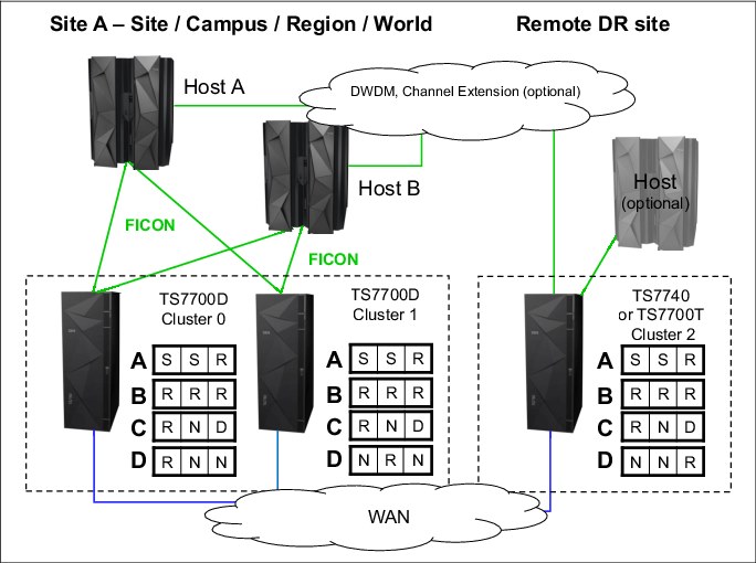
Figure G-3 Three-cluster HA and DR with two TS7700Ds and one TS7700T
Setting up the configuration
The parameter settings are listed in Table G-4. All settings are for exercise purposes only.
Table G-4 Environment for a three-cluster grid for HA and DR
|
Fact
|
Number/State
|
Comment
|
|
Number of clusters
|
Three
|
Divided in two or three data centers.
|
|
Type of cluster
|
Two TS7720s within metro distance and one TS7740 in a DR location as a hybrid cluster
|
|
|
Host connection
|
|
Hosts are connected only to the local Cluster 0 and Cluster 1.
|
|
SAA
|
Disabled
|
|
|
DAA
|
Disabled
|
|
|
Override settings
|
Copy Count Policy Override set to 2
|
|
|
Synchronous Deferred on Write Failure Option
|
ON
|
|
|
Cluster family
|
None
|
|
Results of this parameter setting
MCA has a parameter setting of S/S/R:
•Data in cache: Because of the Synchronous mode copy, the data is written synchronously to Cluster 0 and Cluster 1. During RUN, the data is also copied to the DR location.
•Mount behavior in normal conditions: Controlled by customer (JES3/JES2); Cluster 0 and Cluster 1 have only host attachment.
•Mount behavior in outage conditions: The same rules for Synchronous mode regarding Write failure ON/OFF apply as in a two-cluster grid, even if a third cluster is available. If Cluster 0 or Cluster 1 is unavailable, the mount is satisfied because the Synchronous Deferred on Write Failure flag is on. The state of Cluster 2 does not have an influence in this S/S mount.
•TVC selection for scratch mounts: Clusters with S are preferred against a cluster with a Run as the I/O TVC.
MCB has a parameter setting of R/R/R:
•Data in cache: If you do not use the Copy Count Override Policy, at RUN time, a valid copy is in each cache (there are three copies, one in each cluster).
•In the example, the Copy Count Override Policy was set to a number of 2. Therefore, by the time that two RUNs complete successfully, which is sufficient for the TS7700 to signal device end, and the job finishes successfully. For MCB, that can result in the situation where two RUNs are processed in the TS7720 in the production environment, and the DR location has no valid copy at RUN time. The remaining RUN copies are produced later.
•Mount behavior in normal conditions: Controlled by customer (JES3/JES2); Cluster 0 and Cluster 1 have only host attachment.
•Mount behavior in outage conditions: Scratch mounts can be run if one TS7720 is available. If both TS7720s are not available, scratch mounts cannot be run because the TS7740 is not connected to the hosts.
•Private mounts can be satisfied if one TS7720 is available.
•TVC selection for scratch mounts: All three clusters are treated as equal in relation to TVC selection.
MCC has a parameter setting of R/N/D:
•Data in cache: At RUN time, Cluster 0 has a valid copy of the data. Cluster 1 has no copy, and Cluster 2 has no copy at RUN, but Cluster 2 receives a copy later. If Cluster 2 was selected as TVC (due to special conditions), Cluster 2 can also have a valid copy at RUN time. The copy to Cluster 0 is processed then on RUN time.
•Mount behavior in normal conditions: Controlled by customer (JES3/JES2); Cluster 0 and Cluster 1 have only host attachment.
•Mount behavior in outage conditions: For scratch mounts, if Cluster 0 fails, the mount might be run on Cluster 1. Even if Cluster 1 has no valid copy, the TVC of Cluster 2 is used as the remote mount. After RUN, Cluster 2 will have a valid copy in the cache, whereas Cluster 1 has no valid copy.
•Private mounts can be run if the deferred copy has already created a valid copy of the logical volume. Cluster 1 is selected as the mount point and Cluster 1 uses the TVC of Cluster 2. After RUN, a valid copy will be only in Cluster 2.
•TVC selection: Cluster 0 is always preferred. Cluster 2 is accepted if Cluster 0 is unavailable. Cluster 1 is not used as the TVC.
|
Important: This copy policy implies that if you have an outage of one component (either Cluster 0 or Cluster 2), only one valid copy of data is available.
|
MCD has parameters RNN, NRN, and NNR. These MCs are necessary for BVIR processing, DR volume testing, and Copy Export runs.
Effect of features on the grid behavior
SAA can be introduced in this example if you want to direct a specific type of workload to a certain TS7720. This might be useful if your TS7720s have different configurations.
DAA might be chosen to ensure that a cluster with a valid copy is selected. In this example, the data associated with MCC and MCD benefits.
The usage of override settings for local cache influences only the TVC selection, as described in “Example 2: Two-cluster grid for HA and DR” on page 904.
Cluster families provide no value in this configuration.
Example 4: Four-cluster grid for HA and DR
This example has two production sites (Site A and Site B) within metro distances. Cluster 0, Cluster 1, Cluster 2, and Cluster 3 are HA clusters and are local to each other (less than 10 kilometers (6.2 miles) apart). All virtual drives connect to the host. The host accesses the 1,024 virtual devices that are provided by Cluster 0, Cluster 1, Cluster 2, and Cluster 3 (see Figure G-4).
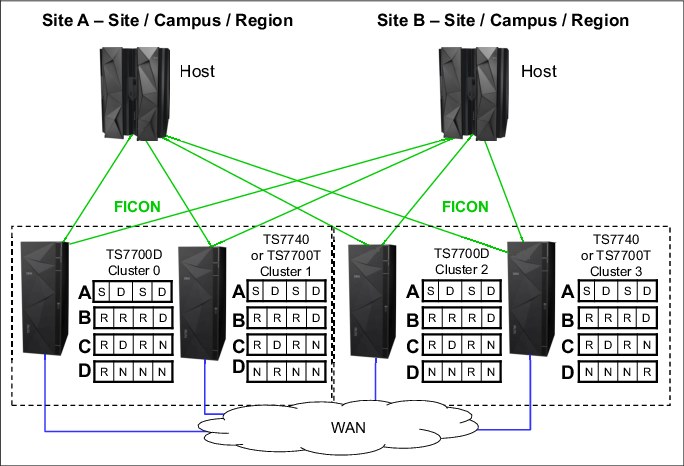
Figure G-4 Examples of a four-cluster grid for HA and DR
In this configuration, there are many different possible consistency point policies available. The section covers three valid configurations and one configuration that is not recommended.
In this example, if a TS7720 reaches the upper threshold of usage, the oldest data that has already been replicated to the TS7740 can be removed from the TS7720 cache. Copy Export can be used from the TS7740 to have a second copy of the migrated data, if required.
Setting up the configuration
The parameter settings are listed in Table G-5.
Table G-5 Environment for a four-cluster grid for HA and DR
|
Fact
|
Number/State
|
Comment
|
|
Number of clusters
|
Four
|
Divided in two data centers.
|
|
Type of cluster
|
One TS7720 and one TS7740 in data center A. One TS7720 and one TS7740 in data center B.
|
|
|
Host connection
|
|
Hosts are connected to all clusters.
|
|
SAA
|
Enabled
|
TS7720s are selected as scratch mount candidates for MCA and MCB.
TS7740 (Cluster 1) is selected as the scratch mount candidate for MCC.
|
|
DAA for private volumes
|
Enabled
|
|
|
Override settings
|
None
|
|
|
Synchronous Deferred on Write Failure option
|
ON
|
|
|
Cluster family
|
None
|
|
Results of this parameter setting
MCA has a parameter setting of S/D/S/D:
•Data in cache: Because of the Synchronous mode copy, the data is written synchronously to Cluster 0 and Cluster 2 (TS7720). Cluster 1 and Cluster 3 (TS7740) receive the data later.
•Mount behavior in normal conditions: Due to the use of SAA, Cluster 0 and Cluster 2 are selected for scratch mounts. For private mounts, DAA selects a cluster according to the rules of DAA.
•Mount behavior in outage conditions: The same rules for Synchronous mode about Write Failure ON/OFF apply as in a two-cluster grid. In the example, Write Failure is set to ON, which enables mounts to be satisfied if one of the synchronous clusters is available.
•If Cluster 0 and Cluster 2 are not available, the mount is not run because SAA is enabled. In this case, you need to disable SAA or select the TS7740 as the scratch candidate mount. Private mounts are run if DAA can find any valid copy of the data in the grid.
•TVC selection for scratch mounts: Clusters with S are preferred against clusters with a Deferred as the I/O TVC.
MCB has a parameter setting of R/R/R/D:
•Data in cache: At RUN, Cluster 0, Cluster 1, and Cluster 2 have a valid copy in cache. Cluster 3 receives a copy later.
•Mount behavior in normal conditions: Due to the use of SAA, Cluster 0 and Cluster 2 are selected for scratch mounts. For private mounts, DAA selects a cluster according to the rules of DAA.
•Mount behavior in outage conditions: If both Cluster 0 and Cluster 2 are not available, the mount is not run because SAA is enabled. In this case, you need to disable SAA or select the TS7740 as the scratch candidate mount. Private mounts are run, if DAA can find any valid copy of the data in the grid.
•TVC selection for scratch mounts: Clusters with R are preferred over clusters with a Deferred as the I/O TVC.
MCC has a parameter setting of R/D/R/N:
•Data in cache: At RUN time, a valid copy is in Cluster 0 and Cluster 2. Cluster 1 (TS7740) receives the data later. Cluster 3 does not receive a copy.
•Mount behavior in normal conditions: Due to the use of SAA, Cluster 0 and Cluster 2 are selected for scratch mounts. For private mounts, DAA selects a cluster according to the rules of DAA.
•Mount behavior in outage conditions: The TS7740 (Cluster 1) is the only cluster that is selected as a scratch candidate in this example. Therefore, scratch mounts can be run only if Cluster 1 is available. Private mounts are run if DAA can find any valid copy of the data in the grid.
•TVC selection for scratch mounts: Cluster 0 and Cluster 2 are preferred, and Cluster 1 might be selected. Cluster 3 is not selected due to the No Copy setting.
Special consideration for this Management Class
This example of MC setup shows characteristics that you need to avoid when you use scratch candidate selection:
•Cluster 1 is the only cluster that is selected for a scratch candidate. This is a single point of failure, which is not necessary in such a configuration.
•Cluster 1 has a definition of Deferred copy. In combination with the scratch candidate selection, the likelihood of remote mount rises.
•Auto removal is allowed for the TS7720. With Auto Removal allowed, some volumes might have only a consistent copy in one of the TS7720 tape drives. Consider having a copy in both of the TS7740s to protect the data against a site loss and against a physical media failure.
MCD has these parameter settings: R/N/N/N, N/R/N/N, N/N/R/N, and N/N/N/R. These MCs are necessary for BVIR processing, DR volume testing, and Copy Export runs.
Effect of features on the grid behavior
The effect of the Override Policy: Copy Count Override is explained in the three-grid configuration and also applies here.
Cluster families have a major influence on the behavior and are introduced in the next example.
Example 5: Four-cluster grid for HA and DR by using cluster families
This example has a similar environment, but there are two changes:
•Cluster 0 and Cluster 1 are defined as family A; Cluster 2 and Cluster 3 are defined as family B.
•SAA is disabled.
The new configuration is shown in Figure G-5.
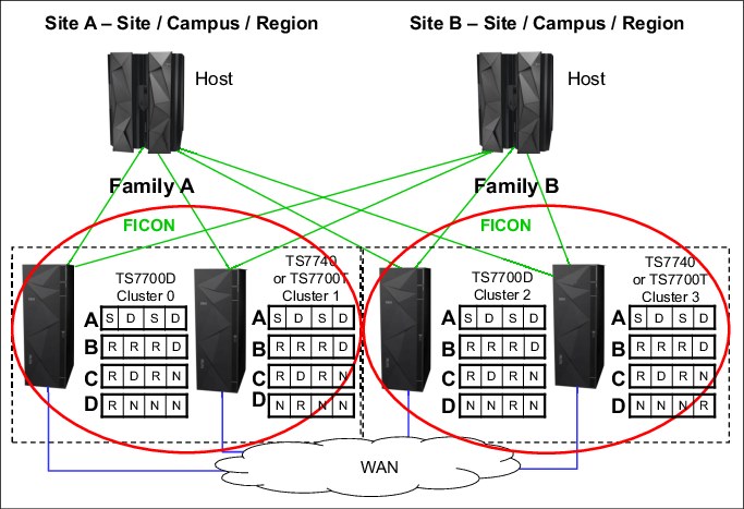
Figure G-5 Examples of a four-cluster grid for HA and DR with cluster families
Setting up the configuration
The parameter settings are listed in Table G-6.
Table G-6 Environment - four-cluster grid for HA and DR
|
Fact
|
Number/State
|
Comment
|
|
Number of clusters
|
Four
|
Divided in two data centers.
|
|
Type of clusters
|
One TS7720 and one TS7740 in data center A (Site A), and one TS7720 and one TS7740 in Site B
|
|
|
Host connection
|
|
Hosts are connected to all clusters.
|
|
SAA
|
Disabled
|
|
|
DAA for private volumes
|
Enabled
|
|
|
Override settings
|
None
|
|
|
Synchronous Deferred on Write Failure option
|
ON
|
|
|
Cluster family
|
Two cluster families, with one cluster family in each site
|
|
Results of this design
MCA has a parameter setting of S/D/S/D:
•For this Copy Consistency Point, the influence of a family is small.
•Data in cache: There is no change to the number of copies available at a certain point in time. Only the copy source is different. Without cluster families defined, all copies were requested from the cluster with the selected I/O cache. With cluster families defined, the copy is requested inside the family from either Cluster 0 (Family A) or Cluster 2 (Family B).
•Mount behavior: No change.
•TVC selection: For a remote mount, normally, the cluster with S is selected. However, a cluster inside the family overrules a cluster outside the family. If Cluster 0 needed a remote mount, the cluster prefers Cluster 1 rather than Cluster 2, even if a physical mount needs to be run.
MCB has a parameter setting of R/R/R/D:
•For this Copy Consistency Point, the introduction of cluster families has the following effect.
•Data in cache: Assume that the Cluster 0 or Cluster 1 TVC was selected as the I/O cache. At RUN, the data is in the cache of Cluster 0, Cluster 1, and Cluster 2. Cluster 3 receives the copy later, but not from the original TVC cache. Instead, Cluster 3 receives the copy from Cluster 2 because it is a member of the same family.
|
Remember: All RUN copies are processed as defined.
For deferred copies, only one copy is transferred between the two sites. All other deferred copies are produced inside the defined family.
|
•Mount behavior in normal conditions: The mount behavior itself remains the same as family clusters. It is under your control to select the appropriate scratch mount candidates or to disable virtual drives. Due to the use of SAA, Cluster 0 and Cluster 2 are selected for scratch mounts. For private mounts, DAA selects a cluster according to the rules of DAA.
•TVC selection: Normally, a cluster with R is preferred against a cluster with Deferred. However, if, in a cluster family, a remote mount occurs, the family overrules this behavior. Therefore, if a cluster needs a remote mount, the cluster prefers a cluster inside the family over a cluster with a RUN outside the family. In the example, that can lead to following situation.
Cluster 2 receives a private mount. Assume that Cluster 2 has no valid copy and initiates a remote mount. Without a cluster family, Cluster 0 (TS7720) is selected if Cluster 0 has a valid copy in the cache. Instead, Cluster 2 prefers to select Cluster 3 as the TVC, which might result in a recall from a stacked volume. If the volume is modified, Cluster 3 already has a valid copy and transfers this copy to all other clusters because of the Copy Consistency Point.
MCD has these parameter settings: R/N/N/N, N/R/N/N, N/N/R/N, and N/N/N/R. These MCs are used for BVIR processing, DR volume testing, and Copy Export runs. For this Copy Consistency Point, the definition of cluster families has no influence.
General example setup for Tape partitions
This example shows a customer environment, with six different types of data. The following table shows the type of data, the likelihood that this data is read again, and the data volumes.
All data volumes are calculated without growth for a basic calculation in this example.
Table G-7 lists the type of data, the likelihood of read, and the daily, and total volume of TB stored.
Table G-7 Data scenario for Tape Partitions
|
|
Likelihood read / customer requirement
|
Daily volume compressed data
|
Total volume in TB / expiration
|
|
HSM ML2
|
High
|
0.3 TB
|
150 TB
|
|
DB2 archive logs
|
Customer wants to keep 10 days in cache
|
1 TB
|
17 TB
|
|
DB2 image copies
|
Customer wants to keep 3 days in cache
|
5 TB
|
150 TB
|
|
Archive data - 4 years and longer
|
Low
|
0.2 TB
|
300 TB expiration 4 years and longer,
|
|
Other Backups A
|
Low
|
15 TB
|
500 TB, 30 days
|
|
Other Backups B
|
Low
|
|
|
|
Other data, like SMF
|
High during the next week, then low
|
0.5 TB
|
730 TB (4 years)
|
|
Other data
|
low
|
0.1 TB
|
Unpredictable
|
The following scenarios can be considered:
•All data in cache: No physical backend.
•All data will be premigrated ASAP to physical tape: No usage of delay premigration.
•HSM ML2 will be kept in cache only, all other data will be premigrated. Tape partitions will be used.
•Delay premigration is used to expire data in cache.
Especially for Example 3 and Example 4, there are several different options. In this appendix, only two options are covered to explain the theory.
The night batch jobs producing the 15 TB from “other backups” are running 5 hours each day. A throughput for 3 TB in an hour is therefore necessary. Assume that this is a steady workload, a compressed host I/O from 875 MBps is expected.
Basic considerations how to find the best configuration and setup
Firstly, the customer has defined some requirements. This is a good starting point for the configuration and setup. Alternatively, there is a total amount of throughput, cache capacity, and cache bandwidth requirements, depending on how the data is treated. The same applies to the amount of premigration queue depth (FC 5274). In the next paragraphs, we calculate to determine whether the configuration and setup would be valid to satisfy the customer needs.
Example 1: All data in cache
To determine, if that is a valid option, it is only necessary to add the total amount of compressed data. In our example, it is obvious that we need more cache than the maximum amount of data we can deliver in one TS7760T (1.3 PB).
So for this example, this is not a feasible solution.
Example 2: All data on physical tape (premigrated ASAP), only one tape partition
First, determine what the minimum requirement for the cache is. That would be at least the amount of data that is written on one day. Adding the numbers, a one-drawer TS7760 with 31.42 TB would be sufficient. However, that does not satisfy the requirements of the customer.
To satisfy the customer requirement, we need to calculate the following information:
•DB2 archive log= 1 TB a day = 10 days in cache = 10 TB
•DB2 image copy = 5 TB a day = 3 days in cache = 15 TB
•Other backup = 15 TB
•Other data = 0.8 TB
•HSM = Unpredictable
Adding the numbers (10 + 15 + 15 + 0.2 + 0.5 + 0.1) = 40.8 TB
A two-drawer configuration (approx. 63 TB) would allow also to have some HSM data in cache.
However, this configuration has the following restrictions:
•It cannot handle the necessary Host I/O sustained throughput.
•Without Tape partitions, the cache can be controlled only with PG1/PG0, therefore the DB2 data and SMF data might not be in cache as requested.
Therefore, this solution is not feasible.
Example 3: HSM ML2 will be kept in cache only, all other data will be premigrated, and tape partitions will be used
To determine the configuration, we first calculate the minimum cache capacity:
•CP0: HSM ML2, 150 TB + 10% free space and contingency = 165 TB.
•CP1: DB2: 25 TB + 10% contingency = 28 TB (rounded).
•CP2: Other data = 15.8 TB. SMF data will be treated with PG1. All other data will be treated as PG0.
In total 208.8 TB are requested, so seven drawers with approx. 219 TB total capacity needs to be installed to satisfy the minimum request for cache capacity.
Looking to the cache bandwidth (see CHAPTER PERFORMANCE), a seven-drawer configuration could provide the necessary sustained throughput, as long no RUN or SYNC copies shall be produced.
If RUN or SYNC is needed (and we strongly suggest that you use them when HSM ML2 synchronous mode copy is used), then a seven-drawer configuration is not sufficient - or no premigration could run during the night batch. This could result in an issue, because 15 TB will not fit in the premigration queue. So we would not recommend this configuration if RUN or SYNC is needed.
Regarding the premigration queue depth, we cannot follow the recommendation to be able to keep a full day of premigration data in the queue, because the customer produces 22 TB a day. In the 5-hour peak, approx. 15 TB are written. That means, that either two TS7700 needs to be installed or the customer needs to accept that premigration during the peak time is essential to not run in throttling. In addition, the customer should consider to review the LI REQ,SETTING2,PRETHDEG / COPYWDEG/TVCWDEG values to be prepared in an unavailable situation of the physical library.
So this could be one feasible option.
Example 4: Delay premigration will be used to expire data in cache
To determine the configuration, we first calculate the minimum cache capacity:
•CP0: HSM ML2, 150 TB + 10% free space and contingency = 165 TB.
•CP1: DB2: 25 TB + 10% contingency = 28 TB (rounded).
•CP2: Other data (backups with 30 days will expire in cache)= 500 TB, + 10 TB for other data. SMF treated with PG1, all other data will be treated as PG0.
That means, that we have to provide 703 TB, which results in 23 drawers. This amount of drawers is capable to run the host I/O in sustained mode, and do also some copy activity.
Because all data from the daily backup will expire in cache, the amount of FC 5274 for the premigration queue needs to be recalculated.
in this example. the daily amount of compressed data is 7 TB, which results in 7 * FC 5274. Depending on the workload profile, you might consider to install only 5 TB to cover the DB2 portion only.
In this example also the number of backend cartridges - and maybe even backend drives would be less than in Example 3.
If 7* FC 5274 is installed, also an unavailability of the physical tape library of 24 hours can be allowed without any throttling issue.
This is also a feasible solution, if the customer allows that no physical copy exists for a part of the backup data. Keep in mind that this data has only a short lifecycle anyway.
..................Content has been hidden....................
You can't read the all page of ebook, please click here login for view all page.