


Configuring a z14 ZR1 server by using Dynamic Partition Manager
This chapter describes how to configure a z14 ZR1 CPC by using Dynamic Partition Manager (DPM). DPM is a management interface that simplifies the configuration and administration of an IBM Z CPC.
This chapter includes the following topics:
16.1 Introduction
DPM is a resource management and operational environment that provides a simplified approach to configuring and managing IBM Z servers1. DPM reduces the barriers to the adoption of IBM Z for new and existing customers.
The DPM implementation provides built-in integrated capabilities that allow advanced virtualization management on IBM Z servers. With DPM, customers can use their Linux and virtualization skills while getting the full value of IBM Z hardware’s robustness and rich security features in a workload optimized environment.
DPM provides facilities to define and run virtualized computing systems by using a firmware-managed environment that coordinates the physical system resources that are shared by the partitions2. The partitions’ resources include processors, memory, network, storage, Crypto, and Accelerators.
DPM is not an extra hypervisor for IBM Z servers. DPM uses the PR/SM hypervisor infrastructure and provides an intelligent and unified interface that allows customers to define, use, and operate the platform virtualization with little or no IBM Z experience.
|
Note: When IBM z14 ZR1 servers are set to run in DPM mode, the following components are supported:
•Linux virtual servers running in a partition
•The KVM hypervisor1 for Linux guests
•z/VM with Linux guests
•Virtual appliances that use the IBM Secure Service Container (SSC) framework
|
1 Available with Linux distributions.
The DPM infrastructure is shown in Figure 16-1.
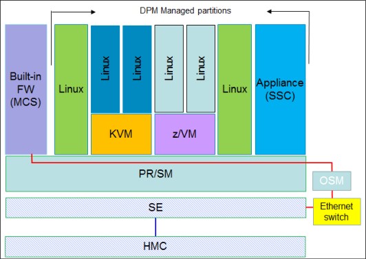
Figure 16-1 High-level overview of DPM implementation
The firmware partition (similar to the PCIe support partition, which is also known as the master control services [MCS] partition), along with the Support Element (SE), provides instrumentation to create and manage the Linux native partitions (used also for deploying kernel-based virtual machine (KVM) code), partitions that run the IBM z/VM hypervisor, or partitions that run appliances that use the Secure Service Container framework.
The connectivity from the SE to the MCS is provided through the internal management network by two OSA-Express 1000BASE-T that are acting as management adapters (OSM).
16.1.1 Prerequisites
This section provides an overview for DPM prerequisites and considerations for supported features. For more information, see the IBM Dynamic Partition Manager (DPM) Guide, SB10-7170.
Prerequisites
The DPM is a mode of operation that requires IBM z14 M0x (Machine Type 3906), IBM z14 ZR1 (Machine Type 3907), IBM z13 (Machine Type 2964 - Driver Level 27), or z13s (Machine Type 2965) CPCs.
|
Feature enablement: DPM is a feature code (FC) 0016 that can be selected during the machine order process. FC 0016 requires one pair of OSA-Express 1000BASE-T adapters, which must be included in the configuration.
When the Z CPC is managed by using DPM, the OSA-Express 1000BASE-T features are dedicated for DPM configuration and cannot be used for any other purpose.
|
16.1.2 Planning considerations
In this section, we provide considerations for installing a new system (create a configuration from scratch) and for switching a system from “traditional” management to use DPM.
We also describe I/O features and other configuration aspects, such as time synchronization and resource allocation.
New system
If the system you are configuring is new (no pre-existing configuration to be saved or migrated), start configuring the system as described in 16.1.4, “Enabling DPM” on page 391.
|
Important: Consider the following points:
•A CPC in DPM mode cannot be part of an Ensemble that is managed by Unified Resource Manager. The HMC that is used to enable the CPC in DPM mode must not be an Ensemble HMC (Primary or Backup Ensemble HMC).
•All definitions that are made for the CPC (if any) before the DPM mode is activated are saved and can be brought back if you choose to revert to standard PR/SM mode. However, when switching the CPC into standard PR/SM mode, any definitions that are made with the CPC in DPM mode are discarded (not saved).
|
Previously configured system
If you are converting a system (configured and managed by using standard or traditional tools) to the use of DPM, you must check the configuration of the system and verify whether you must save any configuration data. This process helps you to decide whether you should revert to “traditional” management tools.
16.1.3 Considerations for I/O features
The following I/O and special purpose features are supported for configuration by using DPM:
•OSA-Express features (all supported features)
•FICON Express (all supported features):
– Fibre Channel Protocol (SCSI)
– FICON (ECKD) DASD
•RoCE Express and RoCE Express2 features (as standard NIC, no SMC-R support)
•IBM zEDC Express (used as an accelerator)
•Crypto Express features (all supported features)
|
Important: Not all channel types are supported for these features. For more information about supported channel types, see the DPM documentation.
|
The following features are not supported when DPM is used to configure and manage your system:
•Coupling features3:
– ICA SR
– Coupling Express Long Reach
•zHyperLink Express
|
Important: Always consult with operating system support for the features’ functionality availability.
|
Internal features
From the available internal capabilities of the z14 ZR1, HiperSockets are supported and configurable by using DPM.4
Time synchronization
If your environment requires time synchronization, the z14 ZR1 includes Server Time Protocol (STP) support. STP support is provided through FC 1021.
STP allows the Z CPC to synchronize its time to an external time source (ETS). At Power On Reset, the CPC retrieves the Time Of Day (TOD) from the SE. Further on, the time of the CPC can be maintained in sync with an ETS by using the SE Network Time Protocol (NTP) client (with STP configured) and STP feature.
When configured, STP creates a Coordinated Timing Network (CTN) that is used for maintaining CPCs in sync with an ETS.
When in DPM mode, a CPC can be configured as a Single Server CTN. Through STP, time synchronization information is provided to the operating systems that is running in the partitions (LPARs) on the CPC.
Operating system support is required for the use of the STP feature. Linux on Z and z/VM support time synchronization by using STP.
|
STP tip: STP provides timing information to all partitions in a CPC. If the CPC uses STP, all active partitions can maintain time synchronization to an external source without requiring external timing source access (through a network connection).
Moreover, the IBM Z CPC is equipped with Pulse Per Second input to increase time synchronization accuracy from 100 ms (standard NTP accuracy) to 10 microseconds when a time source (NTP server) is used that also includes a Pulse Per Second output (PPS).
|
For more information, see the following publications:
•Server Time Protocol Planning Guide, SG24-7280
•Server Time Protocol Implementation Guide, SG24-7281
•Server Time Protocol Recovery Guide, SG24-7380
Processor considerations
The following processor characterization types can be configured and used for customer workload on a CPC that is managed by using DPM:
•Central Processor (CP)
•Integrated Facility for Linux (IFL)
|
Important: Simultaneous Multi-Threading (SMT) is not supported on CPs. As of this writing, only IFLs support SMT.
|
The following processor types cannot be configured when the CPC is managed by using DPM:
•IBM Z Integrated Information Processor (zIIP)
•Integrated Coupling Facility (ICF)
16.1.4 Enabling DPM
Enabling DPM is a disruptive action. The selection of DPM mode of operation is done by using a SE task that is named Enable Dynamic Partition Manager under the CPC Configuration menu, as shown in Figure 16-2 on page 392.
For more information about DPM enabling, see IBM 3907 Installation Manual, GC28-6973.
|
Note: During the machine installation1 or in preparation for DPM (later), the IBM SSR connects the two OSA Express 1000BASE-T cables to the Ethernet Top of Rack (management) switches in the designated ports.
|
1 The DPM mode of operation setting is normally performed at machine installation time by the service support representative (SSR).

Figure 16-2 Enabling DPM mode of operation from the SE CPC configuration tasks
After the option is selected, a new window opens (see Figure 16-3) in which you must enter the two OSA Express 1000BASE-T ports that are designated for DPM management (connected to the two switches in the frame during the Z server installation).

Figure 16-3 Entering the OSA ports that are used by the management network
After entering the OSA adapter port numbers that were cabled to the switches, click Enable.
The SE then restarts. When finished, the DPM mode becomes active and operational.
The DPM mode welcome window is shown in Figure 16-4. The three options at the bottom (Getting Started, Guides, and Learn More) include mouse-over functions that briefly describe their meaning or provide more functions.

Figure 16-4 DPM mode welcome window
The welcome window that is shown in Figure 16-4 opens only when at least one HMC-defined CPC is active in DPM mode. This DPM mode can be identified by the presence of the Adapters information. Otherwise, the traditional HMC window is presented when you log on to the HMC (the items that are indicated by the arrows in Figure 16-4 are not displayed).
16.2 Configuring Server Time Protocol
|
Note: This configuration task is optional. You can skip this task if you do not plan to use STP for CPC time synchronization.
However, if you plan to use STP, this task is performed before partitions are configured and activated; otherwise, the partitions might need to be reactivated to acquire any timing configuration from STP if configured later.
STP configuration for a single server CTN configuration requires SE connectivity to an external NTP server (external time source). Alternatively, the HMC can be configured as an NTP server.
|
STP can be used if time synchronization for our environment is required. Although STP is an optional feature (FC 1021), it is highly recommended (for more information, see “Time synchronization” on page 390).
This section describes the procedure that we used in our environment to enable STP for a DPM-managed CPC.
16.2.1 Configuring External Time Source on the Support Element
|
Note: Ensure that you configured at least one NTP server to be accessible to the SE. Communication with the designated NTP server also can be encrypted. For more information about configuring encryption for the NTP server, see the HMC Version 2.14.0 documentation.
|
The STP configuration information can be checked by using the CPCs Support Element interface. In our example, we used the following process to check the configuration:
1. From the HMC interface, with a user that includes System Programmer (Sysprog) authority, we selected our CPC. Then, clicked Recovery → Single Object Operations (SOO). In the SOO interface, we select the CPC and then, click the System (Sysplex) Time task (see Figure 16-5).

Figure 16-5 Accessing System (Sysplex) Time menus form the SE
The window that shown in Figure 16-6 opens. If the CPC is newly installed or STP was not yet configured, no Timing Network (CTN) information is available.

Figure 16-6 System (Sysplex) Time configuration information (SE view)
2. The ETS information must be configured. We click the ETS Configuration tab, as shown in Figure 16-7.

Figure 16-7 External Time Source tab (not configured)
3. We select Use NTP and enter the necessary information. Then, we check the NTP server connectivity (by clicking Query), as shown in Figure 16-8 on page 396. After the NTP servers are contacted, the NTP stratum and time source information are shown.
The Adjust NTP threshold option can be used if your NTP servers might drift away from a lower NTP stratum level (through NTP reconfiguration).
|
Note: The lower the NTP stratum value, the better the time synchronization accuracy for your system.
|

Figure 16-8 Entering ETS information
4. We click Apply to save ETS information. This information is used later to configure the CTN.
5. We close the System (Sysplex) Timer task and log off from the support element.
16.2.2 Configuring the Coordinated Timing Network (HMC)
We completed the following steps to configure the CTN for the CPC in DPM mode:
1. We continue STP configuration on the HMC by selecting the CPC and then clicking Manage System Time, as shown in Figure 16-9.

Figure 16-9 The Manage System Time task on the HMC
2. In our environment, the HMC is used to manage multiple CPCs. The Manage System Time task shows information about the CTN configuration for all configured CTNs.
For a new CPC, no predefined CTN information is available; therefore, we enter a name (see HMC help) for our CTN.
We use a created CTN with the ID ITSO2. The CPC we configured for DPM is not part of any CTN now. It is shown as STP stratum 0; therefore, it is considered a candidate for the ITSO2 CTN, as shown in Figure 16-10.
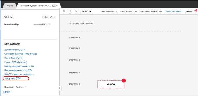
Figure 16-10 CTN candidate
3. We click Setup new CTN and start configuring the single server CTN, as shown in Figure 16-11. Because this server is a single server CTN, no Backup Time Server or Arbiter are available for this configuration.

Figure 16-11 Setting up a new CTN
4. In our example, we specify our CPC as a member in the CTN, as shown in Figure 16-12 on page 398. Click NEXT.

Figure 16-12 Choosing CTN member
5. We select our CPC (see Figure 16-13) as the Preferred Time Server (PTS) and skip selecting a BTS and Arbiter.

Figure 16-13 Selecting the PTS
6. We select the CTS as the Preferred Time Server (PTS), as shown in Figure 16-14.

Figure 16-14 Choosing Current Time Server
7. We proceed to setting the Leap Seconds, Time Zone information, and we set the date and time, as shown in Figure 16-15. We configured the External Time Source (ETS) in steps 1 - 4, as described in 16.2.1, “Configuring External Time Source on the Support Element” on page 394.

Figure 16-15 Set date and time
8. After clicking NEXT, we check the configuration before confirming any changes, as shown in Figure 16-16.

Figure 16-16 Single Server CTN (pending Confirm Changes)
9. After the configuration is applied, the CTN is active and the CPC time of day is directed to the ETS. The result is shown in Figure 16-17 on page 401.
|
Saving the CTN configuration across PORs: The resulting default configuration allows other CPC to be added to this CTN (“unrestricted CTN”). However, because no coupling links are used, this addition is not possible.
Also, the configuration of an unrestricted CTN does not persist after a Power-on-Reset (POR); that is, the configuration is not saved. Therefore, the CTN must be reconfigured after a POR.
To save the CTN configuration across PORs, the CTN membership must be restricted as described next.
|
T
Figure 16-17 CTN configuration result - Unrestricted CTN
10. We restrict the CTN membership to save (persist) the configuration after a PRO, as shown in Figure 16-18.

Figure 16-18 Restricting CTN membership
16.3 Configuring partitions
In this section, we describe how to configure three types of supported partitions: Linux, z/VM, and SSC.
After the CPC is activated in DPM mode, you can configure the system. The configuration process includes the following high-level tasks:
•Planning and checking available resources (processor, memory, adapters, accelerators, cryptographic cards, and devices)
•Configuring storage adapters and environment
•Configuring partitions
For more information about how to configure your system by using DPM, see IBM Dynamic Partition Manager (DPM) Guide, SB10-7170, which is available at the IBM Resource Link website (login required).
16.3.1 Checking system resources
This section describes how to browse the interface for more information about system resources.
System overview
Figure 16-19 shows a system overview of CPC that is managed by DPM.

Figure 16-19 System Details: General information
Figure 16-20 shows the system status.

Figure 16-20 Status window
Processor and Memory
The installed and available processor and memory resources are shown in Figure 16-21.

Figure 16-21 Processors and Memory window
Adapters
The installed adapters summary usage information is shown in Figure 16-22.

Figure 16-22 Adapters summary window
Adapters information
To check the detailed list of adapters, click Manage Adapters (see Figure 16-22 on page 403). A new tab opens in which detailed adapter information is listed (see Figure 16-23). You can filter the adapters based on functionality, as highlighted at the top of the table.

Figure 16-23 Adapter list
|
Tip: The OSA-Express Adapters that are highlighted in the middle of Figure 16-23 are configured as OSM (management adapters). These two adapters cannot be used for any other purpose.
|
16.3.2 Preliminary task: Storage configuration
Starting with DPM 3.1, support for FICON (ECKD storage) and FCP (SCSI storage) is provided. DPM provides a Storage configuration task, which is required before allocating external storage to your LPARs.
You can filter the adapter list to identify the available storage adapters, as shown in Figure 16-24 on page 405. The adapters are shown as “Unconfigured”.
Now, you must proceed with the storage configuration to select the protocol to be used for storage access for each adapter and configure the storage (access the storage subsystem, allocate storage space, and so on).

Figure 16-24 Checking available FICON Express adapters
Complete the following steps:

Figure 16-25 Accessing the “Configure Storage” task
2. In the Configure Storage window, configure the cards’ (adapters’) protocol (FICON or FCP), request storage, and configure FICON connections (switches/directors and storage devices).
In our test environment, we used FCP (SCSI) storage; therefore, we selected FCP for our adapters, as shown in Figure 16-26.

Figure 16-26 Storage cards configuration
Identify the adapters that you plan to use (unused adapters are marked as NONE), click the wanted protocol (FCP or FICON). Then, save the configuration and return to main menu (see Figure 16-25 on page 405).
3. After the storage adapter protocol is saved, the status of the adapter is reflected in the Manage Adapters task (see the red arrow Figure 16-25 on page 405), as shown in Figure 16-27 on page 407.

Figure 16-27 Storage adapters available for allocation to partitions
For more information about configuring FICON (ECKD) storage, see IBM Dynamic Partition Manager (DPM) Guide, SB10-7170.
16.3.3 Configuring a Linux partition
This section describes how to create a Linux partition by using the Standard configuration menu. We present the same steps for configuring a partition by using the Advanced menu as described in 16.3.6, “Configuring partitions by using Advanced menus” on page 424.
We used the following process:
1. To configure a partition, we start with the Systems Management interface on the HMC, select the CPC to be configured. Then, in the Tasks pane, we select New Partition, as shown in Figure 16-28.

Figure 16-28 New Partition task selection
2. The menu that is shown in Figure 16-29 opens. We select Okay, got it to use the standard partition configuration menus.
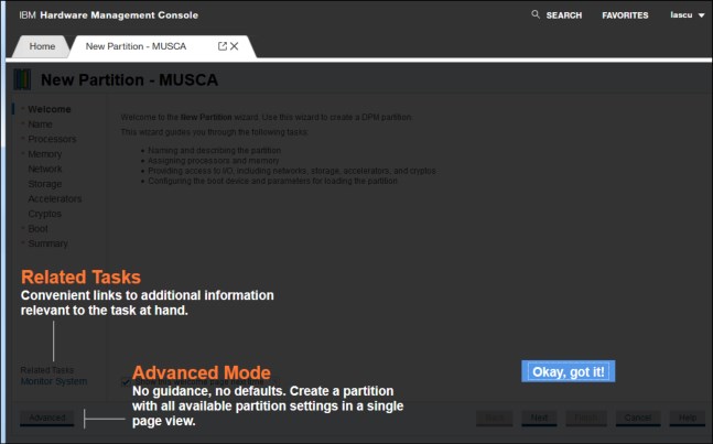
Figure 16-29 Emphasizing the configuration menus options (Standard / Advanced)
Figure 16-30 shows the standard New Partition configuration (wizard) menu. Later in this chapter, we also create an LPAR by using the Advanced menus.

Figure 16-30 Initial menu for configuring partitions (New Partition wizard)
3. The basic information for a partition (name, description, and type) are configured in the next menu, as shown in Figure 16-31. We select the partition type as Linux and click Next.

Figure 16-31 Partition name, description, and type
Depending on the partition type, several processor types (as they are characterized in the machine configuration) can be used. For Linux partitions, only CP or IFL processor types are supported, as shown in Figure 16-32.

Figure 16-32 Available processor types for Linux partition

Figure 16-33 Selecting IFLs for the partition
5. In the next menu (see Figure 16-34), we select the amount of memory to be made available for our partition. The “desired” amount is 16 GB and the maximum amount is 24 GB.

Figure 16-34 Memory selection
6. After the memory is selection, we click Next and start configuring adapters for our partition. Figure 16-35 on page 411 shows the Network Interface Card (NIC) selection window.

Figure 16-35 NIC selection
7. We selected an OSA-Express adapter and created one device (Device number 0001) for our partition, as shown in Figure 16-36.

Figure 16-36 Network device configured
8. We select a storage access (host bus) adapter for our partition, as shown Figure 16-37 on page 412. Because we use SCSI protocol for storage access, we select an adapter that is configured as FCP.
|
Note: For more information about Linux on Z device support and configuration, see the IBM Knowledge Center page for Linux on Z and LinuxONE.
|

Figure 16-37 Selecting FCP adapter
Figure 16-38 shows the NPIV device (device 0004) that was created for our partition.

Figure 16-38 FCP (NPIV) device
9. If wanted, we select Accelerators and Cryptos. However, these components can be added later. We chose to skip Accelerators and Cryptos configuration and proceed to selecting Boot options, as shown in Figure 16-39.

Figure 16-39 Selecting Linux partition boot options
10. After selecting the partition boot options, we finalize creating the partition by clicking Finish, as shown in see Figure 16-40.

Figure 16-40 Finalizing partition definition
The options that are available when the partition is created are shown in Figure 16-41.

Figure 16-41 More task options after partition creation
11. Because we need information about the partition’s storage device configuration, we chose to export WWPNs. WWPNs information is required for SAN zoning and storage access (LUN Masking).
|
Note: This book does not describe how to install an operating system or any other software in a partition. For more information about such installations, see your software of choice (operating system, hypervisor, or appliance) installation documentation.
|
16.3.4 Configuring a z/VM partition
This section describes configuring a partition for running the z/VM hypervisor.
Because the procedure is similar to configuring a Linux partition, we emphasize only the differences from the procedure that is described in 16.3.3, “Configuring a Linux partition” on page 407. For more information, see 16.3.6, “Configuring partitions by using Advanced menus” on page 424.
Complete the following steps:
1. To configure a partition, start with the Systems Management interface on the HMC. Select the CPC to be configured. Then, in the Tasks pane, select New Partition, as shown in Figure 16-42.

Figure 16-42 New Partition task selection
Figure 16-43 shows the standard New Partition configuration (wizard) menu. Later on in this chapter, we also create an LPAR by using the Advanced menus.

Figure 16-43 Initial menu for configuring partitions (New Partition wizard)
2. The basic information for a partition (name, description, and type) are configured in the next menu, as shown in Figure 16-44. Select the partition type as z/VM and click Next.

Figure 16-44 Partition name, description, and type
3. Make the following selections:
– Processor resources (similar to Linux partition)
– Memory resources (similar to Linux partition)
– Network adapters and configure network devices (similar to Linux partition)
– Host bus adapter and configure storage devices (similar to Linux partition)
4. Configure the accelerator adapter (zEDC) to our partition, as shown in Figure 16-45. Select the wanted adapter click OK.

Figure 16-45 Selecting an accelerator adapter for the partition
5. An accelerator device (0001) is created, as shown in Figure 16-46. Click Next to configure a Crypto adapter.

Figure 16-46 Accelerator device (data compression)
Figure 16-47 shows selecting the Crypto adapter.

Figure 16-47 Cryptographic adapter selection (Crypto selected as an accelerator)
A cryptographic domain must be selected for the configured partition, as shown in Figure 16-48.

Figure 16-48 Selecting cryptographic domain for the selected adapter
6. Select the control domain, as shown in Figure 16-49.

Figure 16-49 Control domain selection
Figure 16-50 shows the Crypto device configured for the z/VM partition.

Figure 16-50 Crypto device configuration
7. Selecting the boot options (similar to what is shown in Figure 16-39 on page 413).
8. After selecting the partition boot options, finalize the partition creation by clicking Finish (see Figure 16-40 on page 413).
9. Save the information about the partition’s storage device configuration by exporting the configured WWPNs. The WWPN information is required for SAN zoning and storage access (LUN Masking).
|
Note: This book does not describe how to install software in a partition. For more information about such installations, see your software of choice (operating system, hypervisor, or appliance) installation documentation.
|
16.3.5 Configuring a Secure Service Container partition
An SSC partition is configured similar to Linux or z/VM partitions. As such, we provide figures for the choices and features that are specific to this type of partition only.
Complete the following steps:
1. To configure a partition, start with the Systems Management interface on the HMC and select the CPC to be configured. Then, in the Tasks pane, select New Partition, as shown in Figure 16-42 on page 415.
2. Select the type of partition (Secure Service Container), as shown in Figure 16-51. For this type of partition, no operating system console is used, only web interface access. For more information about the user information configuration, see your documentation.

Figure 16-51 Secure Service Container partition description
3. Select the processor resources (CP or IFL).
4. Select the memory that is required for this partition (wanted and maximum).
5. Select the Network Interface Card adapter for this partition, as shown in Figure 16-52 on page 422.
|
Note: A NIC device is required for this type of partition.
|

Figure 16-52 NIC selection
6. Configure TCP/IP information for the NIC (otherwise, the installer interface might not be accessible). The configuration we used is shown in Figure 16-53.

Figure 16-53 NIC description and IP information

Figure 16-54 NIC configuration
8. Configure the storage adapter (HBA). In our example, we used FCP storage (see Figure 16-38 on page 412).
9. Optionally, you can configure Accelerators and Cryptos (if required by the code that runs in the partition).
10. After you see the available boot options, you can select to boot in installer mode (which is required if you want to install code on the storage that is allocated to the partition), as shown in Figure 16-55.

Figure 16-55 Boot options for SSC partition

Figure 16-56 Secure Service Container partition summary
12. Save the information about the partition’s storage device configuration by exporting the configured WWPNs. The WWPN information is required for SAN zoning and storage access (LUN Masking).
|
Note: This book does not describe how to install software in a partition. For more information about such installations, see your software of choice (operating system, hypervisor, or appliance) installation documentation.
|
16.3.6 Configuring partitions by using Advanced menus
In this scenario, we describe how to configure a Linux partition by using the Advanced menus. The Advanced menus allow a system administrator5 who is familiar with the system to take a more granular approach in resource management and allocation.
For example, the Advanced menus allow configuring dedicated processor resources (only shared processor resources can be configured by using the standard (wizard) menus).
Complete the following steps:
1. Select the Advanced menus, as shown in Figure 16-57.

Figure 16-57 Initial menu for configuring partitions - selecting Advanced menus

Figure 16-58 Advanced mode switch confirmation
3. In the Advanced menu (see Figure 16-59) window, scroll down to configure all resources.
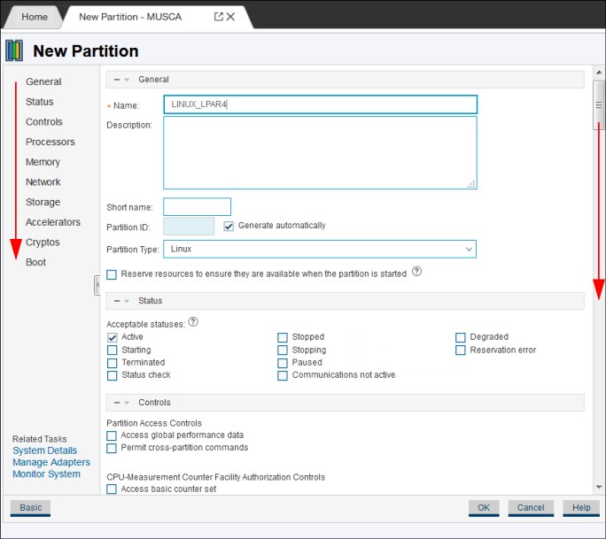
Figure 16-59 New Partition - Advanced menu
Because these configuration steps are similar to the standard and wizard mode, we do not cover these steps here.
16.3.7 Changing partition properties
After the partition is configured, its characteristics can be changed by using the Partition Details menu that is available in the Systems Details tab, as shown in Figure 16-60.

Figure 16-60 System Details tab
In the System Details tab, click Start Options (or scroll down to the Start Options section). Then, select the wanted partition and open the Partition Details tab.
The extra configuration parameters that are not presented when a new partition is configured by using the standard and wizard configuration menu can be changed after the partition is created.
The Partition Details tab (see Figure 16-61) is used to browse the partition configuration.

Figure 16-61 Partition details
Some of the other partition resources and properties that can be configured by using the Advanced menu include Dedicated processors, as shown in Figure 16-62.

Figure 16-62 Configuring Dedicated processors for a partition
1 IBM LinuxONE servers also can be managed by using DPM.
2 DPM uses the term partition, which is the same as logical partition (LPAR).
3 InfiniBand coupling features are not supported on z14 ZR1. Although these features might be supported on systems that support DPM, the InfiniBand features are not configurable or usable when the CPC is managed by DPM.
4 Other internal features include Internal Shared Memory (ISM) communications that are used for SMC-D, Internal Coupling (IC), and Virtual Flash Memory (VFM). These features are not supported in DPM mode.
5 System administrator role is equivalent to System Programmer (HMC role).
..................Content has been hidden....................
You can't read the all page of ebook, please click here login for view all page.