


Mapping CHIDs to CHPIDs by using the CMT
This chapter describes a detailed scenario for the use of the CHPID Mapping Tool (CMT).
This chapter includes the following topics:
4.1 Validating the 3907 work IODF
To validate the 3907 work input/output definition file (IODF) by using the hardware configuration definition (HCD), complete the following steps:
1. Select HCD option 2.12. Build validated work I/O definition file. Review the message list and correct any errors.
2. Press PF3 to continue. The Requested action successfully processed message is displayed.
3. Select HCD option 6.4. View I/O Definition File Information. The IODF type is now indicated as Work - Validated (see Figure 4-1).
|
+---------------- View I/O Definition File Information -----------------+
| |
| |
| IODF name . . . . . . : 'ITSO1.IODF78.WORK' |
| IODF type . . . . . . : Work - Validated |
| IODF version . . . . . : 5 |
| |
| Creation date . . . . : 2018-03-06 |
| Last update . . . . . : 2018-03-08 10:43 |
| |
| Volume serial number . : DZ3P02 |
| Allocated space . . . : 5000 (Number of 4K blocks) |
| Used space . . . . . . : 2158 (Number of 4K blocks) |
| thereof utilized (%) 86 |
| Activity logging . . . : No |
| Multi-user access . . : No |
| Backup IODF name . . . : |
| |
| Description . . . . . : |
| |
| |
| |
| F1=Help F2=Split F3=Exit F9=Swap F12=Cancel |
+-----------------------------------------------------------------------+
|
Figure 4-1 View I/O Definition File Information: Validated work IODF
4.2 Creating the IOCP for the CHPID Mapping Tool
To create the input/output configuration program (IOCP) for the CHPID Mapping Tool, complete the following steps:
|
z/OS V2.3 HCD
+------ Activate or Process Configuration Data ------+
| |
| |
| Select one of the following tasks. |
| |
| 3 1. Build production I/O definition file |
| 2. Build IOCDS |
| 3. Build IOCP input data set |
| 4. Create JES3 initialization stream data |
| 5. View active configuration |
| 6. Activate or verify configuration |
| dynamically |
| 7. Activate configuration sysplex-wide |
| 8. *Activate switch configuration |
| 9. *Save switch configuration |
| 10. Build I/O configuration data |
| 11. Build and manage System z cluster IOCDSs, |
| IPL attributes and dynamic I/O changes |
| 12. Build validated work I/O definition file |
| |
| * = requires TSA I/O Operations |
| F1=Help F2=Split F3=Exit F9=Swap |
| F12=Cancel |
+----------------------------------------------------+
|
Figure 4-2 Activate or Process Configuration Data: Building IOCP for MUSCA
2. HCD displays the list of available processors (see Figure 4-3). Select the MUSCA processor by entering a forward slash (/) next to it and press Enter.
|
+-------------------------- Available Processors ---------------------------+
| Row 1 of 3 |
| Command ===> __________________________________________________________ |
| |
| Select one. |
| |
| Processor ID Type Model Mode Description |
| CETUS 3906 M03 LPAR Cetus |
| LEPUS 2965 N20 LPAR Lepus |
| / MUSCA 3907 ZR1 LPAR Musca |
| **************************** Bottom of data ***************************** |
| |
| |
| |
| F1=Help F2=Split F3=Exit F7=Backward F8=Forward |
| F9=Swap F12=Cancel F22=Command |
+---------------------------------------------------------------------------+
|
Figure 4-3 Available Processors: Selecting a processor for IOCP file
3. HCD displays a panel on which you enter information about the IOCP input data set to be created (see Figure 4-4). Complete the following fields:
– Title1: IODF78
– IOCP input data set: 'ITSO1.IODF78.IOCPIN.MUSCA'
– Input to Stand-alone IOCP: Yes
– Job statement information: Complete this information for your installation.
|
+------------------------- Build IOCP Input Data Set -------------------------+
| |
| |
| Specify or revise the following values. |
| |
| IODF name . . . . . . . . . : 'ITSO1.IODF78.WORK' |
| Processor ID . . . . . . . : MUSCA |
| Title1 . IODF78 |
| Title2 : ITSO1.IODF78.WORK - 2018-03-08 10:43 |
| |
| IOCP input data set |
| 'ITSO1.IODF78.IOCPIN.MUSCA' |
| Input to Stand-alone IOCP? Yes (Yes or No) |
| |
| Job statement information |
| //WIOCP JOB (ACCOUNT),'NAME',MSGCLASS=T |
| //* |
| //* |
| //* |
| //* |
| //* |
| |
| F1=Help F2=Split F3=Exit F5=Reset F9=Swap F12=Cancel |
+-----------------------------------------------------------------------------+
|
Figure 4-4 Build IOCP Input Data Set: Data fields to be updated
4. Press Enter. HCD submits a batch job to create the data set.
5. In Time Sharing Option (TSO), verify that the data set that you created exists and contains IOCP statements (see Figure 4-5). This data set is used as input into the CHPID Mapping Tool.
|
ID MSG1='IODF78', *
MSG2='ITSO1.IODF78.WORK - 2018-03-08 10:43', *
SYSTEM=(3907,1),LSYSTEM=MUSCA, *
TOK=('MUSCA',008001117A883907104328120118067F00000000,00*
000000,'18-03-08','10:43:28','........','........')
RESOURCE PARTITION=((CSS(0),(LEPUS0A,A),(LEPUS0B,B),(LEPUS0C,C*
),(LEPUS0D,D),(LEPUS0E,E),(LEPUS0F,F),(LEPUS01,1),(LEPUS*
02,2),(LEPUS03,3),(LEPUS04,4),(LEPUS05,5),(LEPUS06,6),(L*
EPUS07,7),(LEPUS08,8),(LEPUS09,9)),(CSS(1),(MUSCA1C,C),(*
MUSCA1F,F),(MUSCA11,1),(MUSCA12,2),(MUSCA13,3),(MUSCA14,*
4),(*,5),(*,6),(*,7),(*,8),(*,9),(*,A),(*,B),(*,D),(*,E)*
),(CSS(2),(*,1),(*,2),(*,3),(*,4),(*,5),(*,6),(*,7),(*,8*
),(*,9),(*,A),(*,B),(*,C),(*,D),(*,E),(*,F)))
FUNCTION FID=A0,VF=1,PCHID=100,PNETID=PERFNET, *
PART=((MUSCA11),(=)),TYPE=ROC2,PORT=1
FUNCTION FID=A1,VF=2,PCHID=100,PNETID=PERFNET, *
|
Figure 4-5 IOCP input data set: Contents (truncated)
Part of the TOK statement is now replaced with dots (see Example 4-1).
Example 4-1 IOCP file (TOK statement)
TOK=('MUSCA',008001117A883907104328120118067F00000000,00*
000000,'18-03-08','10:43:28','........','........') 
These dots ensure that this IOCP file cannot be written to a processor and used for a power-on reset. This precaution is needed because this IOCP file was created from a validated work IODF and not a production IODF. IOCP files that can be used for a power-on reset can be generated from a production IODF only.
|
Important: When an IOCP statement file is exported from a validated work IODF by using HCD, it must be imported back to HCD for the process to be valid. The IOCP file cannot be used directly by the IOCP program.
|
6. Download this IOCP file from TSO to the CMT workstation. Use a workstation file transfer facility, such as the one in the IBM Personal Communications Workstation Program, or any equivalent 3270 emulation program. Be sure to use TEXT as the transfer type. In this example, the file is named MUSCAin.iocp.
4.3 Assigning CHIDs to CHPIDs using the CMT
The following steps use the IOCP statements from HCD steps and the 3907 order process (CFReport). Use the CHPID Mapping Tool to assign CHIDs to each of the CHPIDs for the 3907.
For this process, the CHPID Mapping Tool (CMT) must be downloaded. For more information about downloading and installing the CMT, see 2.5, “CHPID Mapping Tool”. If CMT is installed, verify that the latest updates are installed.
The version of CHPID Mapping Tool that is used for the following figures is 6.19. Check for the latest version on IBM Resource Link.
For more information, see the CHPID Mapping Tool User’s Guide, GC28-6984.
Use the CHPID Mapping Tool to complete the following steps:
1. Import the CFReport file into the CMT.
2. Import the IOCP file into the CMT.
3. Resolve CHPIDs with a CHID conflict.
4. Process the hardware resolution.
5. Manually resolve the CS5 CHPIDs.
6. Set the priority for single-path control units and other control units that override the CHPID Mapping Tool default priorities and Automatic Mapping.
7. Resolve the CHPIDs that are not connected to control units.
8. Create the CHPID Mapping Tool reports.
9. Create an updated IOCP statements file for transfer back into the IODF file.
4.4 Importing the CFReport file into the CHPID Mapping Tool
To import the CFReport file into the CHPID Mapping Tool, complete the following steps:
1. Start the CMT on your workstation.
2. CMT asks for a project name and location of the CMT work files. We used MUSCA_upg as the project name (see Figure 4-6).

Figure 4-6 Creating a CHPID Mapping Tool Project
3. Specify that the CFReport and IOCP input file panel is displayed. For this step, we input only the CFReport file for now.
|
Attention: To import the CFReport File into the CHPID Mapping Tool, a Customer Number must be contained in the CFReport File.
|
4. Import the CFReport file into the CHPID Mapping Tool by specifying the name in the CFReport file field. Then, click Finish (see Figure 4-7).

Figure 4-7 Specifying the CFReport file
If you click Finish but did not select an IOCP file, you receive the message that is shown in Figure 4-8. Click OK.

Figure 4-8 Warning message for not specifying an IOCP file
A window shows the progress of reading the CFReport file (see Figure 4-9).

Figure 4-9 Reading the CFReport file
CMT might issue a warning message if it cannot determine that the Adapter IDs in the CFReport file (see Figure 4-10). Click OK.

Figure 4-10 Temporary AID Values Assigned
5. The information from the CFReport file is displayed in the Hardware pane (see Figure 4-11).

Figure 4-11 Imported CFReport file
4.5 Importing the 3907 IOCP file into the CHPID Mapping Tool
To import the validated 3907 IOCP file into the CHPID Mapping Tool, complete the following steps:

Figure 4-12 Importing the IOCP file
2. Select the IOCP file on your workstation to import into the CHPID Mapping Tool and click Finish (see Figure 4-13).

Figure 4-13 Specifying the IOCP file for import
|
Note: As described in 3.2.5, “Deleting any unsupported items in the repeated 2965” on page 37, z14 ZR1 (machine type 3907) does not support InfiniBand coupling links. Therefore, all CHPIDs of type CIB must be deleted in the IOCP file before you import the file into the CHPID Mapping Tool.
|
3. In the Projects window, under the Input tab, expand the IOCP tab, right-click the IOCP file, and select Read Selected IOCP (see Figure 4-14).

Figure 4-14 Reading the selected IOCP
A window displays the progress information (see Figure 4-15).

Figure 4-15 Processing the IOCP file
Another window might be displayed that provides a selection regarding what type of upgrade you are performing (see Figure 4-16):
– IOCP file represents current configuration
– IOCP file represents proposed configuration
In our example, we selected IOCP file represents proposed configuration because we added I/O during the upgrade process from a 2965 to a 3907. Click OK.

Figure 4-16 Processing the IOCP file
The CHPID Mapping Tool displays the information from the CFReport file and the IOCP file in the Hardware Resolution pane. By default, the Hardware Resolution view (see Figure 4-17) includes the following tabbed panes:
– Projects
– Hardware Resolution
– Adapter Type Summary
Hardware Resolution is the middle pane and the Adapter Type Summary is on the right.

Figure 4-17 Hardware Resolution after Imported IOCPfile
The Adapter Type Summary pane displays a table with helpful information. It summarizes the number of used and available channels for the hardware channel types (used, available, and device count).
In the example, the CHPID Mapping Tool can show some of the following output:
•Hardware Resolution: This window lists all CHPIDs that were found and the Status column shows the CHPID information to be investigated. In the example, investigate the status. The status messages and possible resolutions are listed in Table 4-1.
Table 4-1 Status messages and possible resolutions
|
Status
|
Description
|
Resolution (if required)
|
|
No hardware found
|
AID values or PCHID values are present that are not found in the hardware. This situation might occur when you replace hardware for an MES and the IOCP file contains a CHID value for the old hardware (the IOCP file contains a CHID value for the hardware being removed).
|
If you use any CHPIDs of IOCP type CS5, the CHPID Mapping Tool cannot automatically assign these CHPIDs. If the AID assignment in the IOCP file is not valid, you can reset it during hardware resolution. You can then use manual mapping to assign the CHPIDs to AIDs.
Complete the following steps for CS5 CHPIDs:
1. Remove the AID values.
2. Complete one of the following tasks:
– Inside the CHPID Mapping Tool, manually map to associate these CHPIDs with AIDs.
– Assign the AID values outside of the tool; for example, by using HCD.
3. Replace the IOCP file.
|
|
Used IOCP types or adapter types exceed the number available. If more IOCP types exist than available, the Adapter Type (in the Hardware Resolution pane) might be empty. If more used than available adapter types exist, the tool indicates this deficiency in the Used and Available columns of the Adapter Type Summary pane.
|
You must complete one of the following tasks:
•Change the IOCP file.
•Purchase more hardware.
•Ignore the CHPID.
|
|
|
Select at least one adapter type.
|
An adapter type is not assigned to the current row.
|
Assign an adapter type to IOCP type.
|
|
Adapter_type is not compatible with IOCP_type.
|
Adapter type that is assigned for the CHPID is not compatible with the IOCP type that is specified by the IOCP file.
|
For more information, see Appendix 4.7.1, “Resetting Incompatible (Hardware - I/O) entries” on page 63.
|
|
Required hardware for type IOCP_type not available.
Example: Required hardware for type FC not available.
|
The CHPID Mapping Tool found no hardware for the specified IOCP type.
|
You must change the IOCP file or obtain more hardware.
|
|
CHID_1 moved to new channel ID: CHID_2
Example: 520 moved to 1E2
|
You are replacing hardware for an MES, and the IOCP file contains a CHID value for the old hardware, which is being removed. This CHID value moved from an old machine to the CHID value for the new hardware. CHID_1 is the first CHID value (for example, 520) and CHID_2 is the second CHID value (for example, 1E2).
|
This status is an informational message; no hardware resolution is required. The message informs you of the new location so you can change this location if you prefer a different assignment.
|
•Manual mapping CS5 CHPIDs: Availability Mapping cannot be used until all CS5 CHPIDs are resolved. You can use manual mapping to resolve any CS5 CHPIDS after which the Availability Mapping function is enabled for use.
•Process the CU Priorities and Automatic Mapping:
– Reset CHPIDs assigned by Automatic Mapping: Selecting this option resets all CHPIDs that were processed by prior availability runs in this session.
By default, this option is selected.
– Reset CHPIDs assigned by Manual Mapping: Selecting this option resets CHPIDs that were assigned a CHID in the Manual window. If this option is not selected, availability CHIDs for these CHPIDs are not reset.
By default, this option is not selected.
– Reset CHPIDs assigned by IOCP (Potential re-cabling): If some of the CHPIDs are assigned in the IOCP Input file, selecting this option resets the CHPIDs. Selecting this option also might require recabling after availability assignments.
Generally, select this option.
– Reset CHPIDs assigned by CMT for config files: The CFReport indicates that you are performing an MES/upgrade, and channels or CHPIDs (or both) exist that might include configuration files that are associated with them. The MES/upgrade might move some of those channel cards.
Regardless of whether the channels are moving, the CHPID Mapping Tool assigns CHIDs to the logical CHPID definitions to keep the CHPID definition associated with its current configuration file, or moves the definition to the new location where the channel is moving.
If you reset the CHPID Mapping Tool assignments, back up the configuration file data before the MES, and restore that data to the new location (the CHID where the affected CHPIDs are assigned) before you use the CHPIDs.
By default, this option is not selected.
If no options are selected, availability works on only CHPIDs that do not include assigned CHIDs.
To give the CHPID Mapping Tool the most choices when you use the availability option, select Reset CHPIDs assigned by IOCP.
|
Attention: If you select Reset CHPIDs assigned by IOCP, any mapped CHPID assignments are rest, which can result in recabling of the server.
|
However, if you select Reset CHPIDs assigned by Automatic Mapping, review the intersects from availability processing carefully to ensure that preserving the previous CHPID-to-CHID relationship does not cause unacceptable availability.
4.6 Resolving CHPIDs with CHID conflicts
The CMT displays the CHPIDs with CHID conflicts (see Figure 4-18).

Figure 4-18 CHPIDs with PCHID conflicts
In the first column of every row, the Hardware Resolution pane contains one of the following symbols:
•An X in a red circle: This symbol indicates an error.
•An exclamation mark in a yellow circle: This symbol indicates a warning or attention message.
•A green check mark: This symbol indicates that the tool successfully resolved the specified Channel Type.
The example includes the following reasons to resolve hardware resolution issues:
•The CHID channel type changed.
•The defined CHID is not compatible with the channel path at a particular location.
•Not enough ports exist in the hardware.
•A type mismatch exists between a CHPID and its associated channel type.
4.7 Resolving hardware issues
In the example, the CHPID Mapping Tool displays an X in a red circle in the first column of the Hardware Resolution pane (see Figure 4-19) that is related to error types: No hardware found and FICON EXP16S+ SX is not compatible with OSD.

Figure 4-19 Hardware resolution status errors
|
More information: For more information about these error messages, see the CHPID Mapping Tool User’s Guide, GC28-6947.
|
The following options must be reset:
•Incompatible (Hardware - I/O) entries
•“Error: No hardware found”
•“Select at least one adapter type”
•“Required hardware for type IOCP_type not available”
• “CHID_1 moved to new channel ID: CHID_2”
4.7.1 Resetting Incompatible (Hardware - I/O) entries
The Channel type that is assigned for the CHPID is not compatible with the IOCP type that is specified by the IOCP file. For this mismatch, you might receive the following message:
Error: Channel_type is not compatible with IOCP_type.
Resolve this problem by resetting the CHID. In our example, the IOCP type is OSD, but the CHID is associated with an FICON card. You cannot assign the OSD type on the FICON card.
The CHPID Mapping Tool displays the error message in the Status column, as shown in Figure 4-20.

Figure 4-20 Channel_type is not compatible with IOCP_type
Select the channel type OSD. The Status is Error: FICON EXP16S+ SX is not compatible with OSD. Right-click in the row and select Reset Incompatible (Hardware - I/O) Entries to remove the CHID values for only those rows (see Figure 4-21).

Figure 4-21 Channel_Type is not compatible with IOCP_type OSD
The tool replaces the X in a red circle with an Attention icon (exclamation mark in a yellow circle), changes the status message, and removes the CHIDs information (see Figure 4-22).

Figure 4-22 Results for reset of incompatible
The CHPID Mapping Tool now displays messages about any CHPID types that were imported from the IODF into the CMT that do not have any associated hardware support in the CFReport file (see Figure 4-23). Click OK. The Adapter Type Summary details also is shown in Figure 4-23.

Figure 4-23 Required Hardware unavailable
Excessive numbers of OSD CHPID types are in the example IODF to show how the CHPID Mapping Tool handles this condition.
You can use the overdefine option to change the CHID value to an asterisk (*) in the IODF. In this way, you can retain the OSD CHPID definitions in the IODF so that you can install OSD CHIDs in the processor later.
|
Tip: Other CHPID types can also be overdefined by entering an asterisk (*) for the CHID value. Overdefining is now supported for CS5 type CHPID definitions.
|
Alternatively, you can remove the OSD CHPID definitions from the IODF.
To continue with our example, complete the following steps:
1. Return to the IODF and change the CHID values for the OSD CHPIDs (or any other CHPIDs that do not include any supporting hardware in the CFReport) to an asterisk (*).
2. Revalidate the IODF by using HCD option 2.12.
3. Re-create the IOCP statements file and transfer it to your workstation.
4. Import the IOCP file by right-clicking the Projects window and selecting Import IOCP File.
|
Tip: If you review the IOCP statements file now, the OSD CHPIDs are still defined in the IODF (although they are omitted from the file).
|
Now, when you click Reset “Channel-Type is not compatible with IOCP_type”, the CHPID Mapping Tool prompts you to resolve some hardware.
4.7.2 Resetting “Error: No hardware found”
An X in a red circle in the first column indicates an error, and the Status column provides the information with value of Error: No hardware found (see Figure 4-24).

Figure 4-24 Error: No Hardware found
In the example, select channel type FC. The Status is Error: No Hardware found. Right-click in the row and select Reset “No hardware found” Entries to remove the CHID values for those rows (see Figure 4-25).

Figure 4-25 Resetting No Hardware found entries
The tool replaces the X with an Attention icon, changes the status message, and removes the CHID information (see Figure 4-26).

Figure 4-26 Results of resetting No hardware found
4.7.3 Resetting “Select at least one adapter type”
The adapter type is not assigned to the current row. Assign an adapter type to the IOCP type by completing the following steps:
1. Click the Adapter Type column in the target row. The tool displays an arrow in the Channel Type column of the target row (see Figure 4-27).

Figure 4-27 Selecting at least one adapter type
2. Click the ellipses (...) box.
3. The tool displays a list of available and compatible card types for the CHPID, as shown in Figure 4-28. Select an adapter type and click OK.

Figure 4-28 Adapter Type Selection
The Used and Available totals change is shown in the Adapter Type Summary tab.
4.7.4 Resetting “Required hardware for type IOCP_type not available”
The CHPID Mapping Tool found no hardware for the specified IOCP type, as shown in the following example:
Required hardware for type CS5 not available.
You must change IOCP file or obtain more hardware.
4.7.5 Resetting “CHID_1 moved to new channel ID: CHID_2”
When moving from old hardware to new hardware (for example, during a miscellaneous equipment specification [MES]), the CHID value that is assigned to a feature can change. This message indicates that the IOCP file contains a CHID value for the old machine that is being removed. The CHID value is changed from the old machine to the CHID value for the new machine.
For example, CHID_1 is the first CHID value that represents the old hardware (for example, 1B0) and CHID_2 is the new value representing the new hardware (for example, 533). In essence, the feature is present in the old and new hardware, but its location (CHID) changed.
This status is an informational message. No hardware resolution is required. The message informs you of the new location so you can change it if you prefer a different assignment.
After you assign all Adapter Types, the Manual Mapping option becomes available.
4.8 Manual mapping to resolve CS5 CHPIDs
In some situations, the Automatic Mapping option is not available. You cannot use automatic mapping until all CS5 CHPIDs are resolved. You can use manual mapping to resolve this task.
To resolve the CS5 CHPIDs, assign the available CHPIDs by completing the following steps:
Figure 4-29 Manual Mapping
2. Ensure that the tool is set to display Manual Mapping in the Hardware → I/O format (see Figure 4-30).

Figure 4-30 Manual Mapping of Hardware → I/O
3. Click every row that includes type ICA SR in the Adapter Type column. The tool displays all the available CHPIDs with IOCP type (see Figure 4-31).

Figure 4-31 Adapter Type of HCA3 and associated CHPID assigned
4. Select one or more empty check boxes in the I/O Config pane to assign the CHPID. In the Hardware pane, the CHPID number is inserted in the CHPID column. In the Assigned By column, the value of Manual is inserted.
If you select more than one CHPID for an ICS SR adapter type, you see the Multiple --> value (see Figure 4-32) inserted in the CHPID and Assigned By columns.

Figure 4-32 Adapter Type of HCA3 and associated multiple CHPID assigned
The Automatic Mapping option becomes available after you assign all the CHPIDs of IOCP type CS5.
4.9 Processing Automatic Mapping then CU Priority
If you are importing an IOCP statements file from a 2965 in which CU Priority values were defined, review the CU Priority values first. The CHPID Mapping Tool can then perform the availability functions for a 3907.
You must assign priorities if you want to make some control units more important (in the CMT processing order) than others, or have two (or more) control units that you want the CMT to process at the same time.
Perform the first availability function by completing the following steps:
1. Click Automatic Mapping.
2. The Reset CHPID Assignments window opens with Reset choices (see Figure 4-33). For the example, select the following two options and then, click OK:
– Reset CHPIDs assigned by Automatic Mapping
– Reset CHPIDs assigned by IOCP (Potential re-cabling required!)

Figure 4-33 Reset CHPID Assignments
|
Tip: The following fourth choice is also available, but only for an upgrade or an MES:
Reset CHPIDs assigned by CMT for config files.
|

Figure 4-34 Reset CHPID assignments warning message
4. Because the 3907 includes availability rules that differ from a 2965, remove all CHID assignments that are still in the IOCP.
5. Click OK.
6. After the CHPID Mapping Tool resets the CHPIDs, it displays the result of the process (see Figure 4-35). Click OK.

Figure 4-35 Availability ran successfully with no errors message

Figure 4-36 Process Intersections run successfully message
The following intersects are available:
C Two or more assigned channels use the same channel card.
S More than half the assigned channels use the same InfiniBand or STI link.
M All assigned channels are supported by the same MBA group.
B More than half the assigned channels are supported by the same MBA Group.
D Assigned channels are on the same daughter card.
|
Tip: Intersect messages inform you of a potential availability problem that was detected by the CMT. However, they do not necessarily indicate an error. It is your responsibility to evaluate whether the condition must be corrected.
|
8. Click Manual Mapping. In the CHPID Groups tab, observe any intersect warnings that were found during automatic mapping and decide whether they are acceptable (see Figure 4-37). The example returned the “C” intersect. This warning indicates that multiple definitions exist on the same I/O card.

Figure 4-37 B Intersect examples
You can now display the results of the channel mapping. You can also sort the report in various ways. For example, you can see how the CHPID Mapping Tool ranked control units.
Complete the following steps to check and set values for items, such as OSC CHPIDs and FCTC CHPIDs, to ensure that the CHPID Mapping Tool allocates these CHPIDs with high CHID availability:
1. Click CU Priorities. By default, this pane is in the center at the top of the window.
2. In the CU Priorities pane, search in the CU Number column for the control units for which you want to set a priority.
3. Enter a priority number for the CU in the Priority column for each row. The CHPID Mapping Tool makes more related changes in the CHPID Groups panes.
4.10 CHPIDs not connected to control units
In the CU Priorities window, click in the CU Number column (see Figure 4-38). The CHPID Mapping Tool shows at the end of the list all CHPIDs that are defined in the IOCP input that are not connected to control units. In the list of CU numbers, the letter “S” precedes all coupling CHPIDs, and the letter “P” precedes all non-coupling CHPIDs.

Figure 4-38 CHPIDs not connected to control units
Review the list for the following reasons:
•Perhaps you forgot to add a CHPID to a control unit and must update the IOCP source before you continue in the CMT.
•The unconnected CHPIDs might be extra channels that you are ordering in anticipation of new control units.
•The unconnected CHPIDs might be coupling links that are being used in coupling facility (CF) images (they do not require control units).
If extra CHPIDs exist for anticipated new control units, consider grouping these CHPIDs with a common priority. Having a common priority allows the availability mapping function to pick CHIDs that can afford your new control unit availability.
4.11 Creating CHPID Mapping Tool reports
The CHPID Mapping Tool offers built-in reports, which are available from the top of the window. You can also print the information from the report by clicking Print. The options to create a Preview Report or Save Report are listed in Figure 4-39.

Figure 4-39 Preview Report and Save Report buttons
Click Preview Report or Save Report to display choices (a list of types of reports). The choices are the same except that Save Report lists an extra selection (see Figure 4-40).

Figure 4-40 Preview Report and Save Report menus
For simplicity, only the following reports are described in this example:
•CHPID Report
•Port Report, sorted by location
•CHPID to Control Unit Report
However, all built-in reports are printed in the same way.
The person who installs the I/O cables during system installation needs one of these reports. The Port Report, sorted by location, is preferable. The installer can use this report to help with labeling the cables. The labels must include the CHID or cage/slot/port information before system delivery.
4.11.1 CHPID Report
To create the CHPID report, complete the following steps:

Figure 4-41 Preview report: CHPID Report
The CHPID Mapping Tool displays the CHPID Report in a Report tab within the CMT (see Figure 4-42).

Figure 4-42 CHPID Report
|
Tip: You can save individual reports as multiple reports in batch.
|
2. Click Save Report.
In the example, when you click CHPID Report, an option window opens (see Figure 4-43). Specify a file name and an external path (location) of where to save the file. If you want to save the report in HTML, select HTML. The tool selects PDF by default. The window is similar for all type of reports. Click Finish.
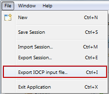
Figure 4-43 Save CHPID Report
The CHPID Report is created by the CHPID Mapping Tool (see Figure 4-44).
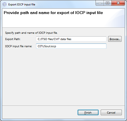
Figure 4-44 CHPID Report example in PDF format
At the end of this CHPID Report is a list of CHPIDs with modified CHID/AID assignments (see Figure 4-45). This report is valuable for moving cables.

Figure 4-45 List of CHPIDs that include modified PCHID/AID assignments
4.11.2 CHPID to Port Report, sorted by location
To create the Port Report that is sorted by location, click Preview Report → Port Report → Sorted by Location. The CHPID Mapping Tool displays the CHPID to Port Report in a Report tab within the CMT (see Figure 4-46).

Figure 4-46 CHPID to Port Report, sorted by location
4.11.3 CHPID to CU Report
This report is created in way that is similar to the CHPID Report. Click Preview Report → CHPID to Control Unit Report. The CHPID Mapping Tool displays the CHPID to Control Unit (CU) Report in a Report tab within the CMT (see Figure 4-47).

Figure 4-47 CHPID to CU Report
4.12 Creating an updated IOCP
Now we need to create a CMT updated IOCP statements file that must be imported back into the IODF by using HCD. This IOCP statements file now includes CHIDs that are assigned to CHPIDs.
To create the IOCP, complete the following steps:

Figure 4-48 Export IOCP input file
|
Requirement: This file must be uploaded to the z/OS image on which you stored the work IODF that you used to create the IOCP input data set.
|

Figure 4-49 Export IOCP File

Figure 4-50 Save session
|
Note: Consider saving your project before exiting the CMT application.
|
4.13 HCD: Updating the 3907 work IODF with CHIDs
After you map the CHIDs to CHPIDs by using the CHPID Mapping Tool, transfer this information back into HCD. In our example, we call the host file name ‘ITSO1.IODF78.IOCPOUT.MUSCA’.
To update the IODF with the CHIDs, complete the following steps:
1. Upload the IOCP file that was created by the CMT (MUSCAout.iocp, in the example) to the z/OS image. Use a file transfer facility, such as the one in IBM Personal Communications or an equivalent FTP program. Be sure to use TEXT as the transfer type and allocate the z/OS file with RECFM=F or FB and LRECL=80.
In the updated IOCP statements file, notice that the CMT keeps a reference to the CCN. Also, note the CU Priority values that were added for the OSC control units.
|
Remember: Control unit priorities are stored in the IOCP output file that is created by CMT. This file is migrated back into HCD. HCD maintains these priorities and outputs them when it creates another IOCP deck. These files are in the form of commented lines at the end of the IOCP deck (see Example 4-2).
|
Example 4-2 Updated IOCP statements file: With CMT statements
CNTLUNIT CUNUMBR=FFFC,PATH=((CSS(2),E1,E0,E3,E2,E5,E4)), *
UNIT=CFP
IODEVICE ADDRESS=(FFA5,007),CUNUMBR=(FFFC),UNIT=CFP
IODEVICE ADDRESS=(FFBD,007),CUNUMBR=(FFFC),UNIT=CFP
IODEVICE ADDRESS=(FFC4,008),CUNUMBR=(FFFC),UNIT=CFP
IODEVICE ADDRESS=(FFCC,008),CUNUMBR=(FFFC),UNIT=CFP
IODEVICE ADDRESS=(FFD4,008),CUNUMBR=(FFFC),UNIT=CFP
IODEVICE ADDRESS=(FFDC,008),CUNUMBR=(FFFC),UNIT=CFP
*CMT* VERSION=000
*CMT* CCN=02433073(CFR from ResourceLink)
*CMT* 1B00.0=0333,1B00.1=0333,PF100.0=0001,PF200.0=0001,PF101.0=0001
*CMT* PF201.0=0001,PF102.0=0001,PF202.0=0001,PF103.0=0001,PF203.0=0001
*CMT* PFD0.0=0001,PFC0.0=0001,PFD1.0=0001,PFB0.0=0001,PFC1.0=0001
*CMT* PFA0.0=0001,PFB1.0=0001,PFA1.0=0001,PFB2.0=0001,PFA2.0=0001
*CMT* PFB3.0=0001,PFA3.0=0001
******************************** Bottom of Data ********************************
2. From the HCD main panel, enter the work IODF name used. Select option 5. Migrate configuration data (see Figure 4-51).
|
z/OS V2.3 HCD
Command ===> ________________________________________________________________
Hardware Configuration
Select one of the following.
5 0. Edit profile options and policies
1. Define, modify, or view configuration data
2. Activate or process configuration data
3. Print or compare configuration data
4. Create or view graphical configuration report
5. Migrate configuration data
6. Maintain I/O definition files
7. Query supported hardware and installed UIMs
8. Getting started with this dialog
9. What's new in this release
For options 1 to 5, specify the name of the IODF to be used.
I/O definition file . . . 'ITSO1.IODF78.WORK' +
|
Figure 4-51 Hardware Configuration: Migrate configuration data
3. From the Migrate Configuration Data panel (see Figure 4-52), select option 1. Migrate IOCP/OS data and press Enter.
|
+----------- Migrate Configuration Data ------------+
| |
| |
| Select one of the following tasks. |
| |
| 1_ 1. Migrate IOCP/OS data |
| 2. *Migrate switch configuration data |
| |
| * = requires TSA I/O Operations |
| |
| F1=Help F2=Split F3=Exit F9=Swap |
| F12=Cancel |
+---------------------------------------------------+
|
Figure 4-52 Migrate Configuration Data: Migrate IOCP/OS data
4. The Migrate IOCP Data panel opens (see Figure 4-53). Complete the following fields and then, press Enter:
Processor ID Use the same ID used to create the IOCP input deck.
OS configuration ID This configuration is the operating system configuration that is associated with the processor.
IOCP only input data set This data set is specified when the MUSCAout.iocp file was uploaded to z/OS.
Processing mode Select option 2 to save the results of the migration. However, before using option 2, try to migrate by using option 1 to validate the operation.
Migrate options Select option 3 for PCHIDS. Only the PCHIDs are migrated into the work IODF.
|
+-------------------- Migrate IOCP / MVSCP / HCPRIO Data ---------------------+
| |
| |
| Specify or revise the following values. |
| |
| Processor ID . . . . . . . . . . . . MUSCA___ + CSS ID . . . . . . _ + |
| OS configuration ID . . . . . . . . ITSOTEST + |
| |
| Combined IOCP/MVSCP input data set . _____________________________________ |
| IOCP only input data set . . . . . . 'ITSO1.IODF78.IOCPOUT.MUSCA'_________ |
| MVSCP only or HCPRIO input data set _____________________________________ |
| Associated with processor ________ + |
| partition ________ + |
| Processing mode . . . . . . . . . . 2 1. Validate |
| 2. Save |
| |
| Migrate options . . . . . . . . . . 3 1. Complete |
| 2. Incremental |
| 3. PCHIDs |
| MACLIB used . . . . . . . 'SYS1.MACLIB' |
| Volume serial number . . . ______ + (if not cataloged) |
| |
| F1=Help F2=Split F3=Exit F4=Prompt F9=Swap F12=Cancel |
+-----------------------------------------------------------------------------+
|
Figure 4-53 Migrate IOCP / MVSCP / HCPRIO Data: Data fields to be updated
HCD displays any errors or warning messages that result from the migration action. In the example, the only message generated indicates that the migration was successful (see Figure 4-54).
|
------------------------- Migration Message List ---------------------------
Query Help
--------------------------------------------------------------------------
Row 1 of 2
Command ===> ___________________________________________ Scroll ===> CSR
Messages are sorted by severity. Select one or more, then press Enter.
/ Statement Orig Sev Message Text
_ I I/O configuration successfully written to the IODF
# ITSO1.IODF78.WORK.
***************************** Bottom of data ******************************
|
Figure 4-54 Migration Message List: successful message
The work IODF now contains the CHPID definitions and the mapping to CHIDs that was done by using the CMT.
5. Press PF3. The following message is displayed:
IOCP/Operating system deck migration processing complete, return code = 0.
6. Press PF3 again.
4.14 More steps and processes
For more information about the next steps, see Chapter 5, “Production IODF and setting up the CPC” on page 85.
..................Content has been hidden....................
You can't read the all page of ebook, please click here login for view all page.