

Hardware Management Console and Support Element
The Hardware Management Console (HMC) supports the functions and tasks that are required to manage the IBM Z CPCs. When tasks are performed on the HMC, the commands are sent to the primary Support Element (SE) of the targeted system, which then issues commands to their respective central processor complex (CPC).
This chapter describes the newest elements for the HMC and SE.
|
Note: The Help function is a good starting point to get more information about all of the functions that can be used by the HMC and SE. The Help feature is available by clicking Help from a drop-down menu that appears when you click your user ID.
For more information, see IBM Knowledge Center.
|
This chapter includes the following topics:
|
Note: Throughout this chapter, z15 refers to IBM z15 Model T01 (Machine Type 8651), unless otherwise specified.
|
10.1 HMC and SE introduction
The HMC is a closed system (appliance), which means that no other applications can be installed on it.
The HMC runs a set of management applications. On z15, the HMC can be a stand-alone computer (mini-tower or rack mounted), or (new with z15) can run (as a Hardware Management Appliance) on the SEs hardware (1U rack-mounted servers that are integrated in z15 A frame).
The SEs are two 1U servers integral to the z15 frame. One SE is the primary SE (active) and the other is the alternative SE (backup). As with the HMCs, the SEs are closed systems, and no other applications can be installed on them.
The HMC is used to set up, manage, monitor, and operate one or more CPCs. It manages IBM Z hardware, its logical partitions (LPARs), and provides support applications. At least one HMC is required to operate an IBM Z. An HMC can manage multiple Z CPCs, and can be at a local or a remote site.
When tasks are performed at the HMC, the commands are routed to the active SE of the z15. The SE then issues those commands to their CPC. One HMC can control up to 100 SEs and 1 SE can be controlled by up to 32 HMCs.
New with z15, a number of “traditional” SE-only functions moved to HMC tasks. On z15, these functions appear as native HMC tasks, but run on the SE. These HMC functions run in parallel with Single Object Operations (SOOs), which simplifies and streamlines system management. For more information about SOOs, see “Single Object Operations” on page 429.
10.1.1 Dynamic Partition Manager support
With Driver 27 (Version 2.13.1), the IBM Dynamic Partition Manager (DPM) was introduced for CPCs that are running Linux only with Fibre Channel Protocol (FCP) attached storage. HMC Driver 32 (Version 2.14.0) with MCLs added support for ECKD FICON disks to the DPM (Release 3.1).
HMC 2.14.1 includes DPM 3.2, with enhanced storage management capabilities. HMC driver 41 (Version 2.15.0) with MCLs added support for FCP and FICON support to the DPM Release 4.0. DPM is a mode of operation that enables customers with little or no knowledge of IBM Z technology to set up the system efficiently and with ease.
For more information, see IBM Knowledge Center, click the search engine window, and enter DPM.
The HMC Remote Support Facility (RSF) provides an important communication to a centralized IBM support network for hardware problem reporting and service. For more information, see 10.4, “Remote Support Facility” on page 427.
10.2 HMC and SE changes and new features
The initial release that is included with z15 is HMC application Version 2.15.0. Use the “What’s New” task to examine the new features that are available for each release. For more information about HMC and SE functions, use the HMC and SE (Version 2.15.0) console help system or see IBM Knowledge Center.
At IBM Knowledge Center, search for “z15 HMC”.
10.2.1 Driver Level 41 HMC and SE new features
The following support was added with Driver 41:
•Hardware Management Appliance
Before z15, in addition to the two integrated rack-mounted SEs, at least one external (stand-alone) HMC is needed (two HMCs are recommended for redundancy).
Starting with z15, the two 1U rack-mounted SEs increased hardware capacity (processor, memory), which allows virtual instances of both HMC and SE to run collocated on the same physical appliance (SE server). The SE application (appliance code) runs as guest of the Hardware Management Appliance, and can be managed by the Virtual Support Element Management task, as shown in Figure 10-1. The SE interface can still be accessed by using the Single Object Operation as usual (by way of HMC web interface).

Figure 10-1 Virtual Support Element Management
The Hardware Management Appliance (HMC application) is accessible by using a remote web browser (the user experience for HMC interaction is free of charge) and can manage N-2 generations systems (z15, z14 ZR1, z14, z13s, and z13).
|
Important: With IBM Hardware Management appliance, shutdown or restart is disruptive to the SE appliance (the SE appliance runs as a guest). An application restart of the HMC appliance is not disruptive to the SE.
Updating the driver or applying HMC MCLs requires planning to ensure that these operations are not disruptive to the CPC by ensuring availability of the primary or alternative SE appliance.
|
Stand-alone (physical) HMCs are also available as rack-mounted or mini-tower.
•Integration of z/OS MFA support for RSA SecurID
HMC Version 2.15.0 provides RSA SecurID authentication by way of centralized support from IBM MFA for z/OS. The MFA policy is defined in RACF and assigned to RACF user IDs, and the RSA SecurID passcode is verified by RSA authentication server.
User Management task is changed on User Definition and User Template Definition to define and select the MFA Server, map HMC user ID to RACF user ID, and select the RACF policy.
•System Recovery Boost status (observe)
System Recovery Boost helps clients improve SLAs at lower risk over service disruptions, both planned and unplanned.
System Recovery boost delivers increased processor capacity for the boost period at the beginning of a planned shutdown or following an IPL so client workloads start can be accelerated and catch up with work through a backlog after the downtime.
Boost capacity can be provided by using one of the following options:
– On a subcapacity machine, the CPs that are allocated to the opt-in LPAR are converted to full-speed CPs during the boost period.
– Dispatching general processor (CP) workloads to zIIPs during the boost period.
– Turbo feature for System Recovery Boost, which is a temporary capacity record that adds physical zIIP capacity to the machine by activating uncharacterized PUs on the system. These added zIIPs can perform CP work as in the second option. This option requires purchase of a prepaid (priced) feature (FC 6802) and is covered by contract terms and conditions (FC 9930 - Boost Authorization).
Processor boost status (usage) is shown on the partition image details (from HMC and SE), as shown in Figure 10-2. System Recovery Boost can be “On” during the boost period (30 minutes for shutdown 60 minutes for IPL), or “Off” during normal LPAR operation. The software image that is running in the LPAR can opt in or opt out the boost facility.

Figure 10-2 Boost status observe from SE
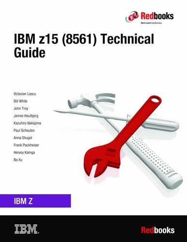
•Change LPAR Group Controls scheduled operation
HMC/SE Version 2.15.0 added a Change LPAR Group Controls scheduled operation (see Figure 10-3) to allow scheduling the change of the CPs/zIIPs/ICFs/IFLs absolute capping status for an LPAR Group.
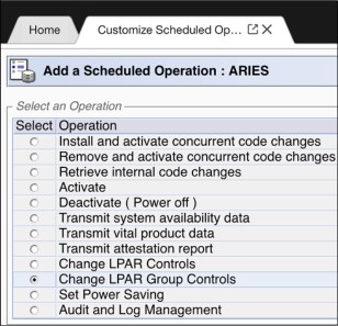
Figure 10-3 Scheduled Operations for Change LPAR Group Controls
•Linux Secure IPL is available for LPARs running on z15 CPCs
This new feature checks the software signature before loading the code into the LPAR storage (memory). When Linux Secure IPL is enabled, the signature of the operating system being loaded is compared with the signature from the Linux on Z distribution provider. The load fails if the signatures do not match.
The feature can be enabled by the selecting the Verify software signature with distributor option in the image profile load Load task, as shown in Figure 10-4. This feature supports Linux on Z running in an LPAR on a z15 CPC.

Figure 10-4 Customize load profile
•Integrated 3270 console security and performance enhancements
On HMC 2.15.0, the internal framework was reworked; therefore, performance for integrated 3270 console is improved. Also, RACF security checking is required based on user logon.
|
Note: Consider the following points:
•Starting with HMC Version 2.15.0, zBX is no longer supported.
•With HMC/SE Driver 41, the Sysplex Time task was removed from the SE; as such, an HMC version 2.15.0 is required to manage STP on a z15 CPC.
•HMC 2.15.0 supports managing N-2 generation CPCs only (z15, z14 ZR1, z14, z13s, and z13).
•The DVD drives for the z15 hardware are no longer available on the new build HMC or the SE.
|
10.2.2 New Rack-mounted HMC and Tower HMC
Feature code (FC) 0063 provides rack-mounted HMC, and FC 0062 provides the tower version of the stand-alone HMC.
The HMC FC0063 (2461-SE3) is a 1U server that can be ordered with an optional IBM 1U rack-mounted tray that features a monitor and a keyboard/pointing device (KMM FC 0154). The HMC system unit and the KMM tray must be rack-mounted in two adjacent 1U locations in the “ergonomic zone” between 21U and 26U in a standard 19-inch rack.
The rack-mounted HMC can be installed in a customer-provided rack (it cannot be mounted in the z15 CPC frames). Three C13 power receptacles are required: two for the system unit and one for the display and keyboard, as shown in Figure 10-5.
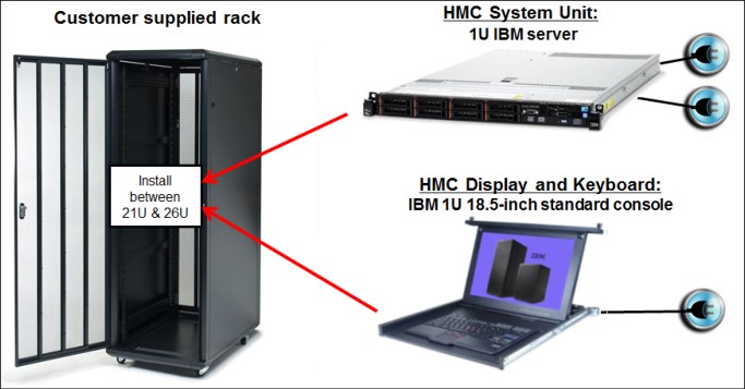
Figure 10-5 Rack-mounted HMC installed in an extra rack
10.2.3 New Support Element
In z15, the SEs are two 1U rack-mounted hardware appliances that are installed at the top of the z15 A-frame, as shown in Figure 10-6.

Figure 10-6 SEs location
Support Element Keyboard Mouse Monitor
New with z15, a new Keyboard Mouse Monitor (KMM) device replaces the previous KMM assembly that was mounted on a swing gate. Consider the following points:
•The device is intended to be used by service personnel only.
•One KMM is used.
•KMM is stored in a cubby at the front of the A-frame, just below the SEs at EIA Rack Unit 39. A USB-C cable and mounting bracket are stored together with the KMM.
•A cable is used to plug the device into a KVM switch at the front or the rear of the rack when servicing the system.
•Switching between SEs is done by using a button that is on the KVM. It also indicates which SE is selected (see Figure 10-7 on page 416).
•The KMM mounting bracket can be used to mount the device to any frame in the system (front or rear sides).
•The KMM can be used on any z15 system (no affinity to system with which it is shipped).
The SE KMM device is shown in Figure 10-7.

Figure 10-7 Support Element KMM device
For more information about the mini-KMM and how to attach it to the A frame, see IBM Z 8561 Installation Manual for Physical Planning, GC28-7002.
10.2.4 New service and functional operations for HMCs and SEs
Because a DVD drive is not available on the HMC or the SE, this section describes some service and functional operations for HMC Version 2.15.0.
Firmware load
Firmware can be loaded by using the following modes:
•USB
If the HMC and SE firmware is shipped on a USB drive when a new system is ordered, the load procedure is similar that was used with a DVD load.
•Electronic
If USB load is not allowed, or when FC 0846 is ordered, an ISO image is used for a firmware load over a local area network (LAN). New build HMCs include HMC/SE ISO images and the HMC provides the server function for loading the code. ISO images can also be downloaded through zRSF or FTP from IBM.
|
Important: The ISO image server (HMC) must be on the same subnet with the target system; that is, the system to be loaded with HMC or SE code from ISO images.
|
Operating system load from removable media or server
z/OS, z/VM, z/VSE, and Linux on Z are planned for USB/network distribution. z/TPF does not use the HMC for code load.
10.2.5 SE driver support with the HMC driver
The driver of the HMC and SE is equivalent to a specific HMC and SE version:
•Driver 22 is equivalent to HMC Version 2.13.0
•Driver 27 is equivalent to HMC Version 2.13.1
•Driver 32 is equivalent to HMC Version 2.14.0
•Driver 36 is equivalent to HMC Version 2.14.1
•Driver 41 is equivalent to HMC Version 2.15.0
An HMC with Version 2.15.0 can support N-2 IBM Z server generations. Some functions that are available on Version 2.15.0 and later are supported only when the HMC is connected to an IBM Z with Driver 41 (z15).
The SE drivers and versions that are supported by the z15 HMC Version 2.15.0 (Driver 41) and earlier versions are listed in Table 10-1.
Table 10-1 Summary of SE drivers
|
IBM Z family name
|
Machine type
|
SE driver
|
HMC/SE version
|
Ensemble node potential
|
|
z15
|
8561
|
41
|
2.15.01
|
No
|
|
z14 ZR1
|
3907
|
32, 36
|
2.14.0, 2.14.1
|
Yesb
|
|
z14
|
3906
|
32, 36
|
2.14.0, 2.14.1
|
Yesb
|
|
z13s
|
2965
|
27
|
2.13.1
|
Yes2
|
|
z13
|
2964
|
22, 27
|
2.13.0, 2.13.1
|
Yesa
|
1 HMC 2.15.0 cannot be used to manage ensembles.
2 A CPC in DPM mode cannot be a member of an ensemble; however, the CPC can still be managed by the ensemble HMC (z14 and earlier systems only).
10.2.6 HMC feature codes
HMCs that are earlier than FC 0095 are not supported for z15 at Driver 41.
The following HMC feature codes are available for a new order:
•FC 0062: M/T 2461-TW3
This feature is the new tower HMC that supports z15, z14 ZR1, z14, z13, and z13s systems.
•FC 0063: M/T 2461-SE3
This feature is the new rack-mounted HMC that supports z15, z14 ZR1, z14, z13, and z13s systems.
The following older HMCs can be carried forward (the carry forward HMCs do not provide all enhancements that are available with FC 0062 and FC 0063):
•Tower FC 0082
•Tower FC 0095
•1U Rack FC 0083
•1U Rack FC 0096
10.2.7 User interface
Starting with HMC Version 2.15.0, HMC Dashboard status was enhanced for accessibility.
In z14, the status bar is in Home tab, and the HMC tasks are started in tabs. While working in a task tab, the console status is not visible. As such, the user cannot be notified of hardware or operating system messages, and other unacceptable status messages until the current task is closed and user returns to the Home tab.
In z15, the status bar was moved to the masthead of the HMC interface, which is always visible (even when working in a task tab), as shown in Figure 10-8.

Figure 10-8 Dashboard status enhancement
10.2.8 Customize Product Engineering Access: Best practice
At times, the HMC or the SE must be accessed in a support role to perform problem determination tasks.
The task to authorize IBM Product Engineering access to the console is shown in Figure 10-9. When access is authorized, an IBM product engineer can use an exclusive user ID and reserved password to log on to the console for problem determination actions.

Figure 10-9 Customize Product Engineering Access tab
As shown in Figure 10-9, the task is available only to users with ACSADMIN authority. Consider the following points:
•Customers must ensure that redundant administrator users (ACSADMIN role) are available for each console.
•Customers must document contact information and procedures.
•The “Welcome Text” task can be used to identify contact information so that IBM Service personnel are informed about how to engage customer administrators if HMC or SE access is needed.
•The Product Engineering access options are disabled by default.
10.3 HMC and SE connectivity
The standard (stand-alone) HMC feature s two Ethernet adapters that enable connectivity to two distinct Ethernet LANs: one for communicating to the support elements, and one for client access through a web browser.
The for CPC management, the SEs on z15 are connected to the Ethernet switches that are installed at the top of the z15 rack, under the SEs. In previous IBM Z systems, the customer network was connected directly to the bulk power hub (BPH). Now, the SEs are directly connected to the customer network by using distinct (separate) Ethernet ports than the SE Ethernet ports that are used for internal CPC management.
10.3.1 Standard HMC connectivity
The HMC communicates with the SE through a customer-supplied Ethernet switch (two switches are recommended for redundancy) that is connected to the J03 or J04 ports on the SEs. Other IBM Z systems and HMCs also can be connected to the same switch (set of switches). Standard HMC connectivity is shown in Figure 10-10.
Figure 10-10 Standard HMC connectivity
|
Note: The HMC must be connected to the SEs by using a switch. Direct connection between the HMC and the SEs is not supported.
|
10.3.2 Hardware Management Appliance
Starting with z15, customers have a choice of the standard (physical) HMC or the new Hardware Management Appliance (FC 0100). Both options can be used to manage the CPCs.
With FC 0100, HMCs and SEs are packaged redundantly inside the Z CPC frame, which eliminates the need for managing separate HMC hardware appliances outside of the z15 CPC.
SE redundant physical appliances use increased capacity devices (1U Rack Mounted). The SE physical appliances run virtual instances of HMC and SE on each physical appliance. This configuration provides redundancy for the HMC and SE.
|
Note: Consider the following points:
•Although Hardware Management Appliance does not require external (stand-alone HMC) hardware, it can be used in parallel with a stand-alone HMC appliance.
•The HMC code runs SE appliance code as a guest of the HMC. This setup requires more planning when updates to the HMC or SE code are required.
•HMC implemented as Hardware Management Appliance can be used to manage N-2 systems (z13/z13s and z14), not only z15.
|
With FC 0100, the SE hardware (2461-SE3) provides the required processing resources and networking connectivity. With Hardware Management Appliance, client access to the HMC is performed by using a browser (remote access because no HMC KMM console is required). Hardware Management Appliance connectivity is shown in Figure 10-11.

Figure 10-11 Hardware Management Appliance connectivity
The Hardware Management Appliance connectivity for multiple CPC environments (z15 N-2 only) is shown in Figure 10-12.
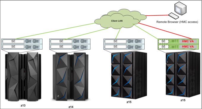
Figure 10-12 HMC virtual appliance managing multiple CPCs
Various methods are available for setting up the network. Designing and planning the HMC and SE connectivity is the clients’ responsibility, based on the environment’s connectivity and security requirements.
|
Security: The configuration of network components, such as routers or firewalls, is beyond the scope of this document. Whenever the networks are interconnected, security exposures can exist. For more information about HMC security, see Integrating the Hardware Management Console‘s Broadband Remote Support Facility into your Enterprise, SC28-6951.
For more information about the HMC settings that are related to access and security, see the HMC and SE console help function or IBM Knowledge Center.
|
10.3.3 Network planning for the HMC and SE
Plan the HMC and SE network connectivity carefully to allow for current and future use. Many of the IBM Z capabilities benefit from the various network connectivity options that are available. The following functions, which depend on the HMC connectivity, are available to the HMC:
•Lightweight Directory Access Protocol (LDAP) support, which can be used for HMC user authentication
•Network Time Protocol (NTP) support
•RSF through broadband
•HMC remote access and HMC Mobile
•RSA SecurID support
•Enablement of the SNMP and CIM1APIs to support automation or management applications, such as IBM System Director Active Energy Manager (AEM).
HMC File Transfer support
FTP, FTPS, and SFTP protocols are now supported on the HMC and SE. All three file transfer protocols (applications) require login ID and password (credentials).
FTPS is based on Secure Sockets Layer cryptographic protocol (SSL) and requires certificates to authenticate the servers. SFTP is based on Secure Shell protocol (SSH) and requires SSH keys to authenticate the servers. Certificates and key pairs are hosted on the z15 HMC Console.
The recommended network topology for HMC, SE, and FTP server is shown in Figure 10-13.

Figure 10-13 Recommended Network Topology for HMC, SE, and FTP server
The following FTP server requirements must be met:
•Support “passive” data connections
•A server configuration that allows the client to connect on an ephemeral port
The following FTPS server requirements must be met:
•Operate in “explicit” mode
•Allows a server to offer secure and unsecured connections
•Must support “passive” data connections
•Must support secure data connections
The SFTP server must support password-based authentication.
The file transfer server choices for HMC are shown in Figure 10-14.

Figure 10-14 FTP protocols drop-down list
FTP through HMC
It is highly recommended to keep IBM Z systems, HMC consoles, and SEs on an isolated network. This approach prevents SEs initiating FTP connections with outside networks and applies to all supported file transfer protocols (FTP, FTPS, and SFTP).
With z15 HMC, all FTP connections that originate from the SEs are taken to HMC consoles. Secure FTP server credentials must be imported to one or more managing HMC consoles.
After the HMC console completes all FTP operations, the HMC console performs the FTP operation on SE’s behalf and returns the results. The IBM Z platform must be managed by at least one HMC to allow FTP operations.
Secure console-to-console communications
Before the z14 server generation, the HMC consoles used anonymous cipher suites to establish console-to-console communication. Anonymous cipher suite is a part of SSL/TLS protocol and it can be used to create point-to-point connections. Anonymous cipher suite does not exchange certificates, which can be a security exposure.
Similar to z14, the z15 HMC consoles abandon anonymous cipher suite and implement an industry standard-based, password-driven cryptography system. The Domain Security Settings are used to provide authentication and high-quality encryption. Because of these changes, we now recommend that clients use unique Domain Security settings to provide maximum security. The new system provides greater security than anonymous cipher suites, even if the default settings are used.
To allow greater flexibility in password selection, the password limit was increased to 64 characters and special characters are allowed for z15 and z14 installations. If communication with older systems before z14 is needed, the previous password limits must be followed (6 - 8 characters, only uppercase and number characters allowed).
For more information about HMC networks, see the following resources:
•The HMC and SE (Version 2.15.0) console help system, or IBM Knowledge Center
•IBM Z 8561 Installation Manual for Physical Planning, GC28-7002
10.3.4 Hardware considerations
The following HMC changes are important for z15:
•No DVD/CD drive with HMC
•IBM does not provide Ethernet switches with the system
DVD/CD Drive
Starting with z15, a DVD/CD drive is not available with the HMC (nor with the SE).
Ethernet switches
Ethernet switches for HMC and SE connectivity are provided by the client. Existing supported switches can still be used.
Ethernet switches and hubs often include the following characteristics:
•A total of 16 auto-negotiation ports
•100/1000 Mbps data rate
•Full or half duplex operation
•Auto medium-dependent interface crossover (MDIX) on all ports
•Port status LEDs
|
Note: The recommendation is to use a switch with 1000 Mbps/Full duplex support.
|
RSF is broadband-only
RSF through a modem is not supported the z15 HMC. Broadband is needed for hardware problem reporting and service. For more information, see 10.4, “Remote Support Facility” on page 427.
10.3.5 TCP/IP Version 6 on the HMC and SE
The HMC and SE can communicate by using IPv4, IPv6, or both. Assigning a static IP address to an SE is unnecessary if the SE communicates only with the HMCs on the same subnet. The HMC and SE can use IPv6 link-local addresses to communicate with each other.
IPv6 link-local addresses feature the following characteristics:
•Every IPv6 network interface is assigned a link-local IP address.
•A link-local address is used on a single link (subnet) only and is never routed.
•Two IPv6-capable hosts on a subnet can communicate by using link-local addresses, without having any other IP addresses assigned.
10.3.6 OSA Support Facility
Since OSA/SF was moved from z/OS to HMC/SE environment, it was noted that it is no longer easy to obtain a global view of all OSA PCHIDs and the monitoring and diagnostic information that was available in the Query Host command.
To address this issue, the following changes were made:
•If a CPC is targeted, the initial window provides a global view of all OSA PCHIDs.
•The user can browse to various OSA Advanced Facilities subtasks from the initial window, which makes the process of getting to them less cumbersome.
•Today’s View Port Parameters and Display OAT entries support exporting data of one OSA PCHID. Also, the data for all OSA PCHIDs can be exported to USB or FTP from the View Port Parameters menu.
•The initial window was changed to display status information of all OSA PCHIDs (see Figure 10-15).

Figure 10-15 OSA Advanced Facilities window
10.3.7 Assigning addresses to the HMC and SE
An HMC can have the following IP configurations:
•Statically assigned IPv4 or statically assigned IPv6 addresses
•Dynamic Host Configuration Protocol (DHCP)-assigned IPv4 or DHCP-assigned IPv6 addressees
•Auto-configured IPv6:
– Link-local is assigned to every network interface.
– Router-advertised, which is broadcast from the router, can be combined with a Media Access Control (MAC) address to create a unique address.
– Privacy extensions can be enabled for these addresses as a way to avoid the use of the MAC address as part of the address to ensure uniqueness.
An SE can have the following IP addresses:
•Statically assigned IPv4 or statically assigned IPv6
•Auto-configured IPv6 as link-local or router-advertised
IP addresses on the SE cannot be dynamically assigned through DHCP to ensure repeatable address assignments. DHCP privacy extensions are not used on the SE.
The HMC uses IPv4 and IPv6 multicasting2 to automatically discover the SEs. The HMC Network Diagnostic Information task can be used to identify the IP addresses (IPv4 and IPv6) which are used by the HMC to communicate to the SEs (of a CPC).
IPv6 addresses are easily identified. A fully qualified IPV6 address features 16 bytes. It is written as eight 16-bit hexadecimal blocks that are separated by colons, as shown in the following example:
2001:0db8:0000:0000:0202:b3ff:fe1e:8329
Because many IPv6 addresses are not fully qualified, shorthand notation can be used. In shorthand notation, the leading zeros can be omitted, and a series of consecutive zeros can be replaced with a double colon. The address in the previous example also can be written in the following manner:
2001:db8::202:b3ff:fe1e:8329
If an IPv6 address is assigned to the HMC for remote operations that use a web browser, browse to it by specifying that address. The address must be surrounded with square brackets in the browser’s address field, as shown in the following example:
https://[fdab:1b89:fc07:1:201:6cff:fe72:ba7c]
The use of link-local addresses must be supported by your browser.
10.3.8 HMC Multi-factor authentication
Multi-factor authentication is an optional and configurable feature on per-user, per-template basis. It enhances security by requiring not only what you know (which is first factor) but also what you have available, which means that only person who owns a specific phone number can log in.
Multi-factor authentication first factor is login and password; the second factor is TOTP (Time-based One-Time Password) that is sent to your smartphone, desktop, or app (for example, Google Authenticator). This TOTP is defined in RFC 6238 standard and uses a cryptographic hash function that combines a secret key with the current time to generate a one-time password.
The secret key is generated by HMC/SE/TKE while the user is performing first factor logon. The secret key is known only to HMC/SE/TKE and to the user’s smartphone. For that reason, it must be protected as much as your first factor password.
Multi-factor authentication code (MFA code) that was generated as a second factor is time-sensitive. Therefore, it is important to remember that it should be used soon after it is generated.
The algorithm within the HMC that is responsible for MFA code generation changes the code every 30 seconds. However, to make things easier, the HMC and SE console accepts current, previous, and next MFA codes. It is also important to have HMC, SE, and smartphone clocks synchronized. If the clocks are not synchronized, the MFA logon attempt fails. Time zone differences are irrelevant because the MFA code algorithm uses UTC.
On z15, HMC Version 2.15.0 provides integration of HMC authentication and z/OS MFA support, which means RSA SecurID authentication is achieved by way of centralized support from IBM MFA for z/OS, with the MFA policy defined in RACF and the HMC IDs assigned to RACF user IDs. The RSA SecurID passcode (from an RSA SecurID Token) is verified by the RSA authentication server. This authentication is supported on HMC only, not on the SE.
User Management task is changed on User Definition and User Template Definition to define and select the MFA Server, and for mapping the HMC user ID to the RACF user ID and selecting the RACF policy.
10.4 Remote Support Facility
The HMC Remote Support Facility (RSF) provides important communication to a centralized IBM support network for hardware problem reporting and service. The following types of communication are provided:
•Problem reporting and repair data
•Microcode Change Level (MCL) delivery
•Hardware inventory data, which is also known as vital product data (VPD)
•On-demand enablement
|
Consideration: RSF through a modem is not supported on the z15 HMC. Broadband connectivity is needed for hardware problem reporting and service.
|
10.4.1 Security characteristics
The following security characteristics are in effect:
•RSF requests always are started from the HMC to IBM. An inbound connection is never started from the IBM Service Support System.
•All data that is transferred between the HMC and the IBM Service Support System is encrypted with high-grade SSL/Transport Layer Security (TLS) encryption.
•When starting the SSL/TLS-encrypted connection, the HMC validates the trusted host with the digital signature that is issued for the IBM Service Support System.
•Data that is sent to the IBM Service Support System consists of hardware problems and configuration data.
|
More information: For more information about the benefits of Broadband RSF and the SSL/TLS-secured protocol, and a sample configuration for the Broadband RSF connection, see Integrating the HMC Broadband Remote Support Facility into Your Enterprise, SC28-6986.
|
10.4.2 RSF connections to IBM and Enhanced IBM Service Support System
If the HMC and SE are at Driver 22 or later, the driver uses a new remote infrastructure at IBM when the HMC connects through RSF for certain tasks. Check your network infrastructure settings to ensure that this new infrastructure works.
At the time of this writing, RSF still uses the “traditional” RETAIN connection. You must add access to the new Enhanced IBM Service Support System to your current RSF infrastructure (proxy, firewall, and so on).
To have the best availability and redundancy and to be prepared for the future, the HMC must access IBM by using the internet through RSF in the following manner: Transmission to the enhanced IBM Support System requires a domain name server (DNS). The DNS must be configured on the HMC if a proxy for RSF is not used. If a proxy for RSF is used, the proxy must provide the DNS.
The following host names and IP addresses are used and your network infrastructure must allow the HMC to access the following host names:
•www-945.ibm.com on port 443
•esupport.ibm.com on port 443
The following IP addresses (IPv4, IPv6, or both) can be used:
•IBM Enhanced support facility:
– IPV4:
• 129.42.54.189
• 129.42.56.189
• 129.42.60.189
– IPV6:
• 2620:0:6c0:200:129:42:54:189
• 2620:0:6c2:200:129:42:56:189
• 2620:0:6c4:200:129:42:60:189
•Legacy IBM support Facility:
– IPV4:
• 129.42.26.224
• 129.42.42.224
• 129.42.50.224
– IPV6:
• 2620:0:6c0:1::1000
• 2620:0:6c2:1::1000
• 2620:0:6c4:1::1000
|
Note: All other previous IP addresses are no longer supported.
|
10.4.3 HMC and SE remote operations
You can use the following methods to perform remote manual operations on the HMC:
•Use of a remote HMC
A remote HMC is a physical HMC that is on a different subnet from the SE. This configuration prevents the SE from being automatically discovered with IP multicast.
A remote HMC requires TCP/IP connectivity to each SE to be managed. Therefore, any customer-installed firewalls between the remote HMC and its managed objects must permit communication between the HMC and the SE. For service and support, the remote HMC also requires connectivity to IBM, or to another HMC with connectivity to IBM through RSF. For more information, see 10.4, “Remote Support Facility” on page 427.
•Use of a web browser to connect to an HMC
The z15 HMC application simultaneously supports one local user and any number of remote users. The user interface in the web browser is the same as the local HMC and has the same functions. Some functions are not available.
|
Note: Remote browser access is the default for the Hardware Management Appliance.
|
Access by using the UFD requires physical access to the HMC. Logon security for a web browser is provided by the local HMC user logon procedures. Certificates for secure communications are provided, and can be changed by the user. A remote browser session to the primary HMC that is managing an ensemble allows a user to perform ensemble-related actions, such as limiting remote web browser access.
You can now limit remote web browser access by specifying an IP address from the Customize Console Services task. To enable or disable the Remote operation service, click Change... in the Customize Console Services window, as shown in Figure 10-16.
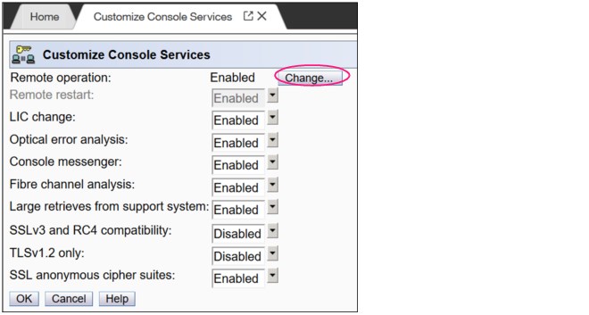
Figure 10-16 Customizing HMC remote operation
Microsoft Internet Explorer, Mozilla Firefox, and Goggle Chrome were tested as remote browsers. For more information about web browser requirements, see the HMC and SE console help system or IBM Knowledge Center.
Single Object Operations
It is not necessary to be physically close to a SE to use it. The HMC can be used to access the SE remotely by using the SOO task. The interface is the same as the interface that is used on the SE. For more information, see the HMC and SE console help system or IBM Knowledge Center.
|
Note: With HMC 2.15.0, certain tasks that required in the past to access to the SE in SOO mode were implemented as HMC tasks. With this enhancement, the HMC runs the tasks on the SE directly, without the need to lock the SE in SOO mode.
|
HMC mobile interface
The new mobile application interface allows HMC users to securely monitor and manage systems from anywhere. iOS and Android HMC applications are available to provide system and partition views, monitor the status and Hardware and Operating System Messages, and receive mobile push notifications from the HMC by using the IBM Z Remote Support Facility (zRSF) connection.
A full set of granular security controls are provided from the HMC console, to the user, monitor only, and mobile app password, including multi-factor authentication. This mobile interface is optional and is disabled by default.
10.5 HMC and SE capabilities
The HMC and SE feature many capabilities. This section describes the key areas. For more information about these capabilities, see the HMC and SE (Version 2.15.0) console help system or IBM Knowledge Center.
With the introduction of the DPM mode for Linux on Z, only CPCs the user interface and user interaction with the HMC changed dramatically; the capabilities underneath are still the same. The figures and command examples that are shown in this section were taken in PR/SM mode.
10.5.1 Central processor complex management
The HMC is the primary place for CPC control. For example, the input/output configuration data set (IOCDS) includes definitions of LPARs, channel subsystems, control units, and devices, and their accessibility from LPARs. IOCDS can be created and put into production from the HMC.
The HMC is used to start the power-on reset (POR) of the system. During the POR, processor units (PUs) are characterized and placed into their respective pools, memory is put into a single storage pool, and the IOCDS is loaded and started into the hardware system area (HSA).
The hardware messages task displays hardware-related messages at the CPC, LPAR, or SE level. It also displays hardware messages that relate to the HMC.
10.5.2 LPAR management
Use the HMC to define LPAR properties, such as the number of processors of each type, how many are reserved, and how much memory is assigned to it. These parameters are defined in LPAR profiles and stored on the SE.
Because Processor Resource/Systems Manager (PR/SM) must manage LPAR access to processors and the initial weights of each partition, weights are used to prioritize partition access to processors.
You can use the Load task on the HMC to perform an IPL of an operating system. This task causes a program to be read from a designated device, and starts that program. You can perform the IPL of the operating system from storage, the USB flash memory drive (UFD), or an FTP server.
When an LPAR is active and an operating system is running in it, you can use the HMC to dynamically change certain LPAR parameters. The HMC provides an interface to change partition weights, add logical processors to partitions, and add memory.
LPAR weights can also be changed through a scheduled operation. Use the Customize Scheduled Operations task to define the weights that are set to LPARs at the scheduled time.
Channel paths can be dynamically configured on and off (as needed for each partition) from an HMC.
The Change LPAR Controls task for z15 can export the Change LPAR Controls table data to a comma-separated value (.csv)-formatted file. This support is available to a user when they are connected to the HMC remotely by a web browser.
Partition capping values can be scheduled and are specified on the Change LPAR Controls scheduled operation support. Viewing more information about a Change LPAR Controls scheduled operation is available on the SE.
One example of managing the LPAR settings is the absolute physical hardware LPAR capacity setting. Driver 15 (zEC12/zBC12) introduced the capability to define (in the image profile for shared processors) the absolute processor capacity that the image is allowed to use (independent of the image weight or other cappings).
To indicate that the LPAR can use the non-dedicated processors absolute capping, select Absolute capping on the Image Profile Processor settings to specify an absolute number of processors at which to cap the LPAR’s activity. The absolute capping value can be “None” or a value for the number of processors (0.01 - 255.0).
The LPAR group absolute capping was the next step in partition capping options that are available on z15, z14 M0x, z14 ZR1, z13s, and z13 CPCs at Driver level 27 and greater. Following on to LPAR absolute capping, LPAR group absolute capping uses a similar methodology to enforce the following components:
•Customer licensing
•Non-z/OS partitions where group soft capping is not an option
•z/OS partitions where ISV does not support software capping
A group name, processor capping value, and partition membership are specified at the hardware console, along with the following properties:
•Set an absolute capacity cap by CPU type on a group of LPARs.
•Allow each of the partitions to use capacity up to their individual limits if the group's aggregate consumption does not exceed the group absolute capacity limit.
•Include updated SysEvent QVS support (used by vendors who implement software pricing).
•Only shared partitions are managed in these groups.
•Specify caps for one or more processor types in the group.
•Specify in absolute processor capacity (for example, 2.5 processors).
•Use Change LPAR Group Controls (as with windows that are used for software group-defined capacity), as shown in Figure 10-17 (snapshot on a z15).

Figure 10-17 Change LPAR Group Controls: Group absolute capping
Absolute capping is specified as an absolute number of processors to which the group's activity is capped. The value is specified to hundredths of a processor (for example, 4.56 processors) worth of capacity.
The value is not tied to the Licensed Internal Code (LIC) configuration code (LICCC). Any value 0.01 - 255.00 can be specified. This configuration makes the profiles more portable, which means that you do not have issues in the future when profiles are migrated to new machines.
Although the absolute cap can be specified to hundredths of a processor, the exact amount might not be that precise. The same factors that influence the “machine capacity” also influence the precision with which the absolute capping works.
LPAR absolute capping can be changed through scheduled operations start with HMC version 2.15.0.
10.5.3 Operating system communication
The Operating System Messages task displays messages from an LPAR. You can also enter operating system commands and interact with the system. This task is especially valuable for entering Coupling Facility Control Code (CFCC) commands.
The HMC also provides integrated 3270 and ASCII consoles. These consoles allow an operating system to be accessed without requiring other network or network devices, such as TCP/IP or control units.
Updates to x3270 support
The Configure 3270 Emulators task on the HMC and TKE consoles was enhanced with Driver 15 to verify the authenticity of the certificate that is returned by the 3270 server when a secure and encrypted SSL connection is established to an IBM host. This 3270 Emulator with encrypted connection is also known as Secure 3270.
Use the Certificate Management task if the certificates that are returned by the 3270 server are not signed by a well-known trusted certificate authority (CA) certificate, such as VeriSign or Geotrust. An advanced action within the Certificate Management task, Manage Trusted Signing Certificates, is used to add trusted signing certificates.
For example, if the certificate that is associated with the 3270 server on the IBM host is signed and issued by a corporate certificate, it must be imported, as shown in Figure 10-18.

Figure 10-18 Manage Trusted Signing Certificates
The import from the remote server option can be used if the connection between the console and the IBM host can be trusted when the certificate is imported, as shown in Figure 10-19. Otherwise, import the certificate by using removable media.

Figure 10-19 Import Remote Certificate example
A secure Telnet connection is established by adding the prefix L: to the IP address:port of the IBM host, as shown in Figure 10-20.

Figure 10-20 Configure 3270 Emulators
10.5.4 HMC and SE microcode
The microcode for the HMC, SE, and CPC is included in the driver or version. The HMC provides the management of the driver upgrade through Enhanced Driver Maintenance (EDM). EDM also provides the installation of the latest functions and the patches (MCLs) of the new driver.
When you perform a driver upgrade, always check the Driver (41) Customer Exception Letter option in the Fixes section at the IBM Resource Link.
For more information, see 9.9, “z15 Enhanced Driver Maintenance” on page 402.
Microcode Change Level
Regular installation of Microcode Change Levels (MCLs) is key for reliability, availability, and serviceability (RAS), optimal performance, and the following new functions:
•Install MCLs on a quarterly basis at a minimum.
•Review hiper MCLs continuously to decide whether to wait for the next scheduled fix application session or to schedule one earlier if the risk assessment warrants.
•Sign On the “IBM Z Security Portal” website and review for security alerts and related MCL fixes.
|
Tip: The IBM Resource Link provides access to the system information for your IBM Z system according to the system availability data that is sent on a scheduled basis. It provides more information about the MCL status of your z15 systems.
For more information about accessing the Resource Link, see the IBM Resource Link website (login required).
At the Resource Link website, click Tools → Machine Information, choose your IBM Z system, and then, click EC/MCL.
|
Microcode terms
The microcode features the following characteristics:
•The driver contains engineering change (EC) streams.
•Each EC stream covers the code for a specific component of z15. It includes a specific name and an ascending number.
•The EC stream name and a specific number are one MCL.
•MCLs from the same EC stream must be installed in sequence.
•MCLs can include installation dependencies on other MCLs.
•Combined MCLs from one or more EC streams are in one bundle.
•An MCL contains one or more Microcode Fixes (MCFs).
How the driver, bundle, EC stream, MCL, and MCFs interact with each other is shown in Figure 10-21.

Figure 10-21 Microcode terms and interaction
MCL Application
By design, all MCLs can be applied concurrently, including:
•During MCL Bundle application.
•During Enhanced Driver Maintenance (Concurrent Driver Upgrade). For example, for z14 at Driver 32, the original GA level, upgrade from Driver 32 to Driver 36 (also applicable to z14 ZR1).
MCL Activation
By design and with planning, MCLs can be activated concurrently. Consider the following points:
•Most MCLs activate concurrently when applied.
•A few MCLs are “Pended” for scheduled activation because activation is disruptive in some way (Recent History: Most commonly seen for traditional OSA-Express features or Crypto-Express features).
•Activate traditional I/O Feature Pended MCL – LIC on the hardware feature:
– Display Pending MCLs using HMC function or Resource Link Machine Information Reports
– Activate using HMC function on a feature basis by PCHID one at a time – disruptive: CONFIG the CHPID OFF to all sharing LPARs, activate, and then CONFIG ON to all
•Activate Native PCIe Pended MCL – LIC on a hardware feature OR Resource Group (RG) LIC:
– Display Pending MCLs using HMC function or Resource Link Machine Information Reports
– Feature LIC: Activate using HMC function on a one feature (PCHID) at a time basis - disruptive: CONFIG FUNCTIONs mapped to the feature OFF to all LPARs, activate, and then CONFIG ON
– RG LIC: Activate using HMC function to each RG in turn – disruptive to all PCHIDs in the RG: CONFIG all FUNCTIONs mapped to all PCHIDs in RG1 OFF, activate, then CONFIG ON. Repeat for all PCHIDs in RG2, RG3, RG4
|
Note: For hardware that does not need CHPID or a FUNCTION definition (for example, Crypto Express), a different method that is specific to the feature is used.
|
•Alternative: Apply and activate all Pended MCLs disruptively with a scheduled Power On Reset (POR)
To discover this “Pended” situation, the following actions are done whenever an MCL is applied:
•Logon HMC and select CPC under “System Management”
•Change Management
•System Information
•Query Additional Actions
Or:
•Logon HMC and select CPC under “System Management”
•Change Management
•Query Channel/Crypto Configure Off/On Pending
Microcode installation by MCL bundle target
A bundle is a set of MCLs that are grouped during testing and released as a group on the same date. You can install an MCL to a specific target bundle level. The System Information window is enhanced to show a summary bundle level for the activated level, as shown in Figure 10-22 on page 437.

Figure 10-22 System Information: Bundle level
10.5.5 Monitoring
This section describes monitoring considerations.
Monitor task group
The Monitor task group on the HMC and SE includes monitoring-related tasks for IBM Z CPCs, as shown in Figure 10-23.

Figure 10-23 HMC Monitor Task Group
Monitors Dashboard task
The Monitors Dashboard task supersedes the System Activity Display (SAD). In the z15, the Monitors Dashboard task in the Monitor task group provides a tree-based view of resources.
Multiple graphical views are available for displaying data, including history charts. The Monitors Dashboard monitors processor and channel usage. It produces data that includes power monitoring information, power consumption, and the air input temperature for the system.
An example of the Monitors Dashboard task is shown in Figure 10-24.

Figure 10-24 Monitors Dashboard task
You can display more information for the following components (see Figure 10-25 on page 439):
•Power consumption
•Environmental
•Aggregated processors
•Processors (with SMT information)
•System Assist Processors
•Logical Partitions
•Channels
•Adapters: Crypto use percentage is displayed according to the physical channel ID (PCHID number)

Figure 10-25 Monitors dashboard Detailed settings
Environmental Efficiency Statistics task
The Environmental Efficiency Statistics task is part of the Monitor task group. It provides historical power consumption and thermal information for the IBM Z CPC, and is available on the HMC.
The data is presented in table format and graphical “histogram” format. The data also can be exported to a .csv-formatted file so that the data can be imported into a spreadsheet. For this task, you must use a web browser to connect to an HMC.
10.5.6 Capacity on-demand support
All capacity on demand (CoD) upgrades are performed by using the SE Perform a Model Conversion task. Use the task to retrieve and activate a permanent upgrade, and to retrieve, install, activate, and deactivate a temporary upgrade. The task shows a list of all installed or staged LICCC records to help you manage them. It also shows a history of recorded activities.
The HMC for IBM z15 features the following CoD capabilities:
•SNMP API support:
– API interfaces for granular activation and deactivation
– API interfaces for enhanced CoD query information
– API event notification for any CoD change activity on the system
– CoD API interfaces, such as On/Off CoD and Capacity Back Up (CBU)
•SE window features (accessed through HMC Single Object Operations):
– Window controls for granular activation and deactivation
– History window for all CoD actions
– Description editing of CoD records
•HMC/SE provides the following CoD information:
– Millions of service units (MSU) and processor tokens
– Last activation time
– Pending resources that are shown by processor type instead of only a total count
– Option to show more information about installed and staged permanent records
– More information for the Attention state by providing seven more flags
HMC and SE are a part of the z/OS Capacity Provisioning environment. The Capacity Provisioning Manager (CPM) communicates with the HMC through IBM Z APIs, and enters CoD requests. For this reason, SNMP must be configured and enabled by using the Customize API Settings task on the HMC.
For more information about using and setting up CPM, see IBM Knowledge Center or the following publications:
•z/OS MVS Capacity Provisioning User’s Guide, SC33-8299
•IBM Z System Capacity on-Demand User’s Guide, SC28-6985
10.5.7 Server Time Protocol support
|
Important: The Sysplex Time task on the SE was discontinued for z15. Therefore, an HMC at Version 2.15.0 is required to manage system time for z15 CPCs.
|
With the Server Time Protocol (STP) functions, the role of the HMC is extended to provide the user interface for managing the Coordinated Timing Network (CTN). Consider the following points:
•IBM Z CPCs rely on STP for time synchronization, and continue to provide support of a pulse per second (PPS) port. Consider the following points:
– A n STP that uses as External Time Source (ETS) a Network Time Protocol (NTP) server with PPS maintains an accuracy of 10 ms
– An STP that uses as ETS an NTP server without PPS maintains accuracy of 100 ms
•The z15 cannot be in the same CTN with zEC12, zBC12, or earlier systems and cannot become member of a mixed CTN.
•An STP-only CTN can be managed by using different HMCs. However, the HMC must be at the same driver level (or later) than any SE that is to be managed. Also, all SEs to be managed must be known (defined) to that HMC.
In a STP-only CTN, the HMC can be used to perform the following tasks:
•Start or modify the CTN ID.
•Start the time (manually or by contacting an NTP server).
•Start the time zone offset, Daylight Saving Time offset, and leap second offset.
•Assign the roles of preferred, backup, and current time servers, and arbiter.
•Adjust time by up to plus or minus 60 seconds.
•Schedule changes to the offsets listed. STP can automatically schedule Daylight Saving Time, based on the selected time zone.
•Monitor the status of the CTN.
•Monitor the status of the coupling links that are started for STP message exchanges.
•For diagnostic purposes, the PPS port state on a z15 can be displayed and fenced ports can be reset individually.
STP changes and enhancements
|
Important: The Sysplex Time task on the SE was discontinued for z15. Therefore, an HMC at Version 2.15.0 is required to manage system time for z15 CPCs.
|
Detailed instructions and guidelines are provided within task workflow. z15 HMC provides a visual representation of the CTN topology. A preview of any configuration action is also shown in topological display. An example of the topology view is shown in Figure 10-26.

Figure 10-26 CTN topology visible on HMC Manage System Time window
Click Current time details for more information and available options (for example, adjusting time zone and leap second offset), as shown in Figure 10-27.

Figure 10-27 Current time details
Enhanced Console Assisted Recovery
Enhanced Console Assisted Recovery (ECAR) speeds up the process of BTS takeover by performing the following steps:
1. When the Primary Time Server (PTS/CTS) detects a checkstop condition, the CEC informs its SE and HMC.
2. The PTS SE recognizes the checkstop pending condition, and calls the PTS SE STP code.
3. The PTS SE sends an ECAR request thorough HMC to the Backup Time Server (BTS) SE.
4. The BTS SE communicates with the BTS to start the takeover.
ECAR support is faster than the original CAR support because the console path changes from a 2-way path to a 1-way path. Also, almost no lag time is incurred between the system checkstop and the start of CAR processing. Because the request is generated from the PTS before system logging, it avoids the potential of recovery being held up.
Requirements
ECAR is available on z15, z14 M0x, z14 ZR1, and z13/z13s systems on Driver 27 and later.
|
Attention: z15 and z14 ZR1 do not support InfiniBand connectivity; therefore, these servers cannot be connected by using IFB coupling/timing links to a z14 (3906), z13, or z13s. As such, in a CTN with servers that still use InfiniBand coupling, CTN roles (PTS, CTS, or Arbiter) must be assigned carefully in such a way that a failure of a CTN role playing server does not affect CTN functionality (loss of synchronization or transition to lower STP Stratum levels).
|
For more information about planning and setup, see the following publications:
•Server Time Protocol Planning Guide, SG24-7280
•Server Time Protocol Implementation Guide, SG24-7281
•Server Time Protocol Recovery Guide, SG24-7380
10.5.8 CTN Split and Merge
z15, z14 ZR1, and z14 support CTN split and CTN merge.
CTN Split
The HMC menus for Server Time Protocol (STP) provide support when one or more systems must be split in to a separate CTN without interruption in the clock source.
The task is available under the Advanced Actions menu in the Manage System Time task. Several checks are performed to avoid potential disruptive actions. If targeted CTN includes only members with the roles, task start fails with error message. If targeted CTN includes at least one system without any roles, the task starts. An informational warning is presented to the user to acknowledge that sysplex workloads are divided appropriately.
Merging two CTNs
When two separate CTNs must be merged in to the single CTN without interruption in the clock source, the system administrator must perform the Join existing CTN action, which is available in the Advanced Actions menu.
|
Note: After joining the selected CTN, all systems within the current CTN are synchronized with the Current Time Server of the selected CTN. A coupling link must be in place that connects the CTS of the selected CTN and the CTS of the current CTN.
|
During the transition state, most of the STP actions for the two affected CTNs are disabled. After the merge is completed, STP actions are enabled again.
For more information about planning and understanding STP server roles, see the following publications:
•Server Time Protocol Planning Guide, SG24-7280
•Server Time Protocol Implementation Guide, SG24-7281
•Server Time Protocol Recovery Guide, SG24-7380
10.5.9 NTP client and server support on the HMC
The NTP client support allows a STP-only CTN to use an NTP server as an ETS. This capability addresses the following requirements:
•Clients who want time synchronization for the servers members of the STP-only CTN
•Clients who use a common time reference across heterogeneous systems
The NTP server becomes the single time source (the ETS) for STP and other servers that are not IBM Z systems (such as AIX®, and Microsoft Windows) that include NTP clients.
The HMC can act as an NTP server. With this support, the z15 can receive the time from the HMC without accessing a LAN other than the HMC and SE network. When the HMC is used as an NTP server, it can be configured to receive the NTP source from the internet. For this type of configuration, a LAN that is separate from the HMC/SE LAN can be used.
HMC NTP broadband authentication support
HMC NTP authentication can be used since HMC Driver 15 (zEC12/zBC12). The SE NTP support is unchanged. To use this option on the SE, configure the HMC with this option as an NTP server for the SE.
Authentication support with a proxy
Some client configurations use a proxy for external access outside the corporate data center. NTP requests are User Datagram Protocol (UDP) socket packets and cannot pass through the proxy. The proxy must be configured as an NTP server to get to target servers on the web. Authentication can be set up on the client’s proxy to communicate with the target time sources.
Authentication support with a firewall
If you use a firewall, HMC NTP requests can pass through it. Use HMC authentication to ensure untampered time stamps.
NTP symmetric key and autokey authentication
With symmetric key and autokey authentication, the highest level of NTP security is available. HMC Level 2.12.0 and later provide windows that accept and generate key information to be configured into the HMC NTP configuration. They can also issue NTP commands.
The HMC offers the following symmetric key and autokey authentication and NTP commands:
•Symmetric key (NTP V3-V4) authentication
Symmetric key authentication is described in RFC 1305, which was made available in NTP Version 3. Symmetric key encryption uses the same key for encryption and decryption. Users that are exchanging data keep this key to themselves. Messages encrypted with a secret key can be decrypted only with the same secret key. Symmetric key authentication supports network address translation (NAT).
•Symmetric key autokey (NTP V4) authentication
This autokey uses public key cryptography, as described in RFC 5906, which was made available in NTP Version 4. You can generate keys for the HMC NTP by clicking Generate Local Host Key in the Autokey Configuration window. This option issues the ntp-keygen command to generate the specific key and certificate for this system. Autokey authentication is not available with the NAT firewall.
•Issue NTP commands
NTP command support is added to display the status of remote NTP servers and the current NTP server (HMC).
For more information about planning and setup for STP and NTP, see the following publications:
•Server Time Protocol Planning Guide, SG24-7280
•Server Time Protocol Implementation Guide, SG24-7281
•Server Time Protocol Recovery Guide, SG24-7380
10.5.10 Security and user ID management
This section addresses security and user ID management considerations.
HMC and SE HD encryption
On z15 (continued emphasis on encryption):
•Password is never stored in clear (one-way hash)
•HMC/SE is a closed appliance; no means exist to get HDD
•All network traffic is TLS encrypted
•HMC/SE features embedded firewall
•Firmware is digitally signed and validated for delivery
•Firmware Integrity Monitoring is used for any attempted tempering post delivery
For HMC/SE Version 2.15.0, HDD encryption uses Trusted Platform Module (TPM) and Linux Unified Key Setup (LUKS) technology.
HMC and SE security audit improvements
With the Audit and Log Management task, audit reports can be generated, viewed, saved, and offloaded. The Customize Scheduled Operations task allows you to schedule audit report generation, saving, and offloading. The Monitor System Events task allows Security Logs to send email notifications by using the same type of filters and rules that are used for hardware and operating system messages.
With z15, you can offload the following HMC and SE log files for customer audit:
•Console event log
•Console service history
•Tasks performed log
•Security logs
•System log
Full log offload and delta log offload (since the last offload request) are provided. Offloading to removable media and to remote locations by FTP is available. The offloading can be manually started by the new Audit and Log Management task or scheduled by the Customize Scheduled Operations task. The data can be offloaded in the HTML and XML formats.
HMC user ID templates and LDAP user authentication
Lightweight Directory Access Protocol (LDAP) user authentication and HMC user ID templates enable the addition and removal of HMC users according to your own corporate security environment. These processes use an LDAP server as the central authority.
Each HMC user ID template defines the specific authorization levels for the tasks and objects for the user who is mapped to that template. The HMC user is mapped to a specific user ID template by user ID pattern matching. The system then obtains the name of the user ID template from content in the LDAP server schema data.
Default HMC user IDs
It is no longer possible to change the Managed Resource or Task Roles of the default user ID’s operator, advanced, sysprog, acsadmin, and service.
If you want to change the roles for a default user ID, create your own version by copying a default user ID.
View-only user IDs and view-only access for HMC and SE
On z15 HMC version 2.15.0, with HMC and SE user ID support, users can be created that have “view-only” access to selected tasks. Support for “view-only” user IDs is available for the following purposes:
•Hardware messages
•Operating system messages
•View activation profiles
•Manage system time
•Manage Coupling Facility Port
•OSA Advanced Facilities
•Advance Facilities
•Configure Channel Path On/Off
•Configure on and off
•Cryptographic Configuration
HMC and SE secure FTP support
You can use a secure FTP connection from a HMC/SE FTP client to a customer FTP server location. This configuration is implemented by using the Secure Shell (SSH) File Transfer Protocol, which is an extension of SSH. You can use the Manage SSH Keys console action, which is available to the HMC and SE, to import public keys that are associated with a host address.
The Secure FTP infrastructure allows HMC and SE applications to query whether a public key is associated with a host address and to use the Secure FTP interface with the appropriate public key for a host. Tasks that use FTP now provide a selection for the secure host connection.
When selected, the task verifies that a public key is associated with the specified host name. If a public key is not provided, a message window opens that points to the Manage SSH Keys task to enter a public key. The following tasks provide this support:
•Import/Export IOCDS
•Advanced Facilities FTP IBM Content Collector Load
•Audit and Log Management (Scheduled Operations only)
•FCP Configuration Import/Export
•OSA view Port Parameter Export
•OSA-Integrated Console Configuration Import/Export
10.5.11 System Input/Output Configuration Analyzer on the SE and HMC
The System Input/Output Configuration Analyzer task supports the system I/O configuration function.
The information that is needed to manage a system’s I/O configuration must be obtained from many separate sources. The System Input/Output Configuration Analyzer task enables the system hardware administrator to access, from one location, the information from those sources. Managing I/O configurations then becomes easier, particularly across multiple systems.
The System Input/Output Configuration Analyzer task runs the following functions:
•Analyzes the current active IOCDS on the SE.
•Extracts information about the defined channel, partitions, link addresses, and control units.
•Requests the channels’ node ID information. The Fibre Channel connection (FICON) channels support remote node ID information, which is also collected.
The System Input/Output Configuration Analyzer is a view-only tool. It does not offer any options other than viewing. By using the tool, data is formatted and displayed in five different views. The tool provides various sort options, and data can be exported to a UFD for later viewing.
The following views are available:
•PCHID Control Unit View shows PCHIDs, channel subsystems (CSS), CHPIDs, and their control units.
•PCHID Partition View shows PCHIDS, CSS, CHPIDs, and the partitions in which they exist.
•Control Unit View shows the control units, their PCHIDs, and their link addresses in each CSS.
•Link Load View shows the Link address and the PCHIDs that use it.
•Node ID View shows the Node ID data under the PCHIDs.
10.5.12 Automated operations
As an alternative to manual operations, an application can interact with the HMC and SE through an API. The interface allows a program to monitor and control the hardware components of the system in the same way a user performs these tasks. On z15, the HMC APIs provide monitoring and control functions through SNMP. The API can get and set a managed object’s attributes, issue commands, receive asynchronous notifications, and generate SNMP traps.
The older system, such as z13’s HMC, supports the CIM as an extra systems management API. Starting with z14, the CIM support is removed.
For more information about APIs, see IBM Z Application Programming Interfaces, SB10-7164.
10.5.13 Cryptographic support
This section describes the cryptographic management and control functions that are available in the HMC and SE.
Cryptographic hardware
z15 systems include standard cryptographic hardware and optional cryptographic features for flexibility and growth capability.
The HMC/SE interface provides the following capabilities:
•Defining the cryptographic controls
•Dynamically adding a Crypto feature to a partition for the first time
•Dynamically adding a Crypto feature to a partition that already uses Crypto
•Dynamically removing a Crypto feature from a partition
The Crypto Express7S, which is a new Peripheral Component Interconnect Express (PCIe) cryptographic coprocessor, is an optional z15 exclusive feature. Crypto Express7S provides a secure programming and hardware environment on which crypto processes are run. Each Crypto Express7S adapter can be configured by the installation as a Secure IBM CCA coprocessor, a Secure IBM Enterprise Public Key Cryptography Standards (PKCS) #11 (EP11) coprocessor, or an accelerator.
When EP11 mode is selected, a unique Enterprise PKCS #11 firmware is loaded into the cryptographic coprocessor. It is separate from the Common Cryptographic Architecture (CCA) firmware that is loaded when a CCA coprocessor is selected. CCA firmware and PKCS #11 firmware cannot coexist in a card.
The Trusted Key Entry (TKE) Workstation with smart card reader feature is required to support the administration of the Crypto Express7S when configured as an Enterprise PKCS #11 coprocessor.
To support the new Crypto Express7S card, the TKE9.2 is needed. An example of the Cryptographic Configuration window is shown in Figure 10-28 on page 448.

Figure 10-28 Cryptographic Configuration window
The Usage Domain Zeroize task is provided to clear the appropriate partition crypto keys for a usage domain when you remove a crypto card from a partition. Crypto Express7/6/5S in EP11 mode is configured to the standby state after the zeroize process.
For more information, see IBM z15 (8561) Configuration Setup, SG24-8860.
Digitally signed firmware
Security and data integrity are critical issues with firmware upgrades. Procedures are in place to use a process to digitally sign the firmware update files that are sent to the HMC, SE, and TKE. By using a hash algorithm, a message digest is generated that is then encrypted with a private key to produce a digital signature.
This operation ensures that any changes that are made to the data are detected during the upgrade process by verifying the digital signature. It helps ensure that no malware can be installed on IBM Z products during firmware updates. It also enables the z15 Central Processor Assist for Cryptographic Function (CPACF) functions to comply with Federal Information Processing Standard (FIPS) 140-2 Level 1 for Cryptographic LIC changes. The enhancement follows the IBM Z focus of security for the HMC and the SE.
The Crypto Express7S (CEX7S) is compliant with CCA PCI HSM. TKE workstation is optional when used to manage a Crypto Express7S feature that is defined as a CCA coprocessor in normal mode. However, it is mandatory when it is used to manage a Crypto Express7S feature that is defined as a CCA coprocessor in PCI-HSM mode or is defined as an EP11 coprocessor (CCA in PCI-HSM mode and EP11 also require a smart card reader plus smart cards with FIPS certification).
10.5.14 Installation support for z/VM that uses the HMC
Starting with z/VM V5R4 and z10, Linux on Z can be installed in a z/VM virtual machine from HMC workstation media. This Linux on Z installation can use the communication path between the HMC and the SE. No external network or extra network setup is necessary for the installation.
10.5.15 Dynamic Partition Manager
DPM is an IBM Z mode of operation that provides a simplified approach to create and manage virtualized environments, which reduces the barriers of its adoption for new and existing customers.
Setting up is a disruptive action. The selection of the DPM mode of operation is done by using the Enable Dynamic Partition Manager function, which is available in the SE CPC Configuration menu. Enabling DPM is performed on the SE and requires a system POR.
|
Attention: The Enabling Dynamic Partition Manager task is run on the SE and is performed by your IBM system service representative (SSR).
|
After the CPC is restarted and you log on to the HMC in which this CPC is defined, the HMC shows the Welcome window that is shown in Figure 10-29.

Figure 10-29 HMC welcome window
New partitions can be added by selecting Get Started. For more information, see IBM Knowledge Center.
1 CIM support was removed from the HMC with Version 2.14.0.
2 For a customer-supplied switch, multicast must be enabled at the switch level.
..................Content has been hidden....................
You can't read the all page of ebook, please click here login for view all page.