

Central processor complex hardware components
This chapter provides information about the new IBM z15™ and its hardware building blocks, and how these components physically interconnect. This information is useful for planning purposes and can help in defining configurations that fit your requirements.
|
Note: Throughout this chapter, z15 refers to IBM z15 Model T01 (Machine Type 8561), unless otherwise specified. The terms frame and rack refer to the same 19-inch packaging of the 1 - 4 units of the system.
|
This chapter includes the following topics:
2.1 Frames and configurations
The z15 Model T01 system is designed in a 19-inch form factor with configuration of 1 - 4 frames that can be easily installed in any data center. The z15 Machine Type 8561 can include 1 - 4 42U EIA (19-inch) frames, which are bolted together. The configurations can include up to five central processor complex (CPC) drawers and up to 12 Peripheral Component Interconnect Express+ (PCIe+) I/O drawers.
The redesigned CPC drawer and I/O infrastructure also lowers power consumption, reduces the footprint, and allows installation in virtually any data center. The z15 server is rated for ASHRAE class A31 data center operating environment.
The z15 server differentiates itself from previous Z server generations through the following significant changes to the modular hardware:
•All external cabling (power, I/O, and management) is performed at the rear of the system
•Flexible configurations: Frame quantity is determined by the system configuration (1 - 4 frames)
•Choice of power Intelligent Power Distribution Unit (iPDU or PDU) or Bulk Power Assembly (BPA)
•Feature codes that reserve slots for plan-ahead CPC drawers
•Added internal water cooling plumbing for systems with more than three CPC drawers
•New PCIe+ Gen3 I/O drawers (19-inch format) supporting 16 PCIe adapters
The power options include PDU-based power or BPA-based power. The z15 server can be configured as a radiator (air) cooled or water cooled (that uses data center chilled water supply) system. Only BPA-based power system can be (optionally) configured for water cooling and with Internal Battery Feature (IBM), while a radiator (air) cooled system has PDU-based power (no Internal Battery Feature [IBF] available for PDU-based systems).
The z15 includes the following basic hardware building blocks:
•19-inch 42u frame (1 - 4)
•CPC (Processor) drawers (1 - 5)
•PCIe+ Gen3 I/O drawers (up to 12)
•CPC drawer Cooling Units: Radiator cooling assembly (RCA) or Water Cooling Unit (WCU)
•Power, with choice of:
– Intelligent Power Distribution Units (iPDU) pairs (2 - 4 per frame, depending on the configuration).
– Bulk Power Regulators (1 - 6 pairs, depending on the configuration)
•Support Elements (two):
– Single KMM2 device (USB-C connection)
– Optional extra hardware for IBM Hardware Management Appliance feature
•24-port 1GbE Switches (two or four, depending on the system configuration)
•Hardware for cable management at the rear of the system
An example of a fully configured system with PDU-based power, five CPC drawers, and maximum 12 PCIe+ I/O drawers is shown in Figure 2-1.

Figure 2-1 Maximum configuration, PDU-based powered system, rear view
An example of a BPA-based powered system with IBF, and a maximum of five CPC drawers and 11 PCIe+ I/O drawers is shown in Figure 2-2.

Figure 2-2 Maximum configuration, BPA-based powered system, rear view
The key features that are used to build the system are listed in Table 2-1 on page 38. For more information about the various configurations, see Appendix D, “Frame configurations” on page 509.
Table 2-1 Key features that influence the system configurations
|
Feature Code
|
Description
|
Comments
|
|
0503
|
Model T01
|
Supports CPs and specialty engines
|
|
0655
|
One CPC Drawer
|
Feature Max34
|
|
0656
|
Two CPC Drawers
|
Feature Max71
|
|
0657
|
Three CPC Drawers
|
Feature Max108
|
|
0658
|
Four CPC Drawers
|
Feature Max145
|
|
0659
|
Five CPC Drawers
|
Feature Max190
|
|
2271
|
CPC1 reserve
|
Reserve A15 location for future add CPC1
(Max34 to Max71 upgrade)
|
|
2272
|
CPC2 reserve
|
Reserve A20 location for future add CPC2
(Max71 to Max108 upgrade)
|
|
Frames and cooling
|
||
|
4033
|
A Frame
|
Radiator (air cooled)
|
|
4034
|
A Frame
|
Water cooled
|
|
4035
|
B Frame
|
Radiator (air cooled)
|
|
4036
|
B Frame
|
Water cooled
|
|
4037
|
Z Frame
|
I/O drawers only
|
|
4038
|
C Frame
|
I/O drawers only
|
|
PDU power
|
||
|
0629
|
200-208V 60A 3 Phase (Delta - “∆”)
|
North America and Japan
|
|
0630
|
380-415V 60A 3 Phase (Wye- ”Y”)
|
Worldwide (except North America and Japan)
|
|
BPA power
|
||
|
0640
|
Bulk Power Assembly (BPA)
|
Quantity 1 = 2 Bulk Power Enclosures
Quantity 2 = 4 Bulk Power Enclosures
|
|
3003
|
Balanced Power Plan ahead
|
Only available with BPA
|
|
3016
|
Bulk Power Regulator (BPR)
|
Quantity per BPA feature: Min. 2, max 6 (in pairs)
|
|
3217
|
Internal Battery Feature (IBF)
|
Quantity per BPA feature: Min. 2, max 6 (in pairs)
|
|
I/O
|
||
|
4021
|
PCIe+ I/O drawer
|
Max. 12 (PDU) or max. 11 (BPA)
|
|
7917
|
Top Exit Cabling
|
Includes cable management top hat
|
|
7919
|
Bottom Exit Cabling
|
Includes rear tailgate hardware at bottom of frame
|
|
7928
|
Top Exit Cabling without Tophat
|
Uses rear slide plates at top of frame
|
Considerations
Consider the following points:
•A-Frame is always present in every configuration
•1u Support Elements (x2) are always in A-Frame at locations A41 and A42
•1u 24-port internal Ethernet switches (x2) are always at locations A39 and A40
More Ethernet switches (x2) are available when necessary in Frame C or B
•I/O PCHID numbering starts with 0100 and increments depending on the number of features that is ordered. There is no PCHID number affinity to a fixed PCIe+ I/O drawer location as with previous systems.
2.1.1 z15 cover (door) design
The standard cover set for z15 model T01 is shown in Figure 2-3. Depending on the number of frames for the configuration, a Z and IBM accent top panel is installed on the outer frames. The single frame configuration combines the accents.
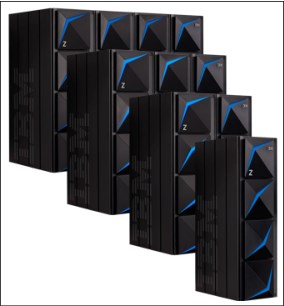
Figure 2-3 z15 Frames
The front doors of the z15 for systems with 1 - 4 frames also is shown in Figure 2-3.
2.1.2 Top exit I/O and cabling
For the z15 Model T01 server, the top exit of all cables for I/O or power is always an option with no feature codes required. Adjustable cover plates are available for the openings at the top rear of each frame.
The Top Exit feature code (FC 7917) provides an optional Top Exit cover enclosure. The optional Top Exit cover enclosure provides cable retention hardware and mounting locations to secure Fiber Quick Connector MPO3 brackets on the top of the frames.
All external cabling enters the system at the rear of the frames for all I/O adapters, management LAN, and power connections.
Feature code 7917 provides a top hat assembly to be installed at the top of each frame in the configuration. This assembly is designed to assist with fiber trunking management.
Overhead I/O cabling is contained within the frames. Extension “chimneys” that were featured with previous Z systems are no longer used.
A view of the top rear of the frame and the openings for top exit cables and power is shown in Figure 2-4. When FC 7917 is installed, the plated adjustable shields are removed and the top exit enclosure is installed.

Figure 2-4 Top exit without and with FC7917
A newly designed vertical cable management guide (“spine”) can assist with proper cable management for fiber, copper, and coupling cables. Depending on the configuration, a spine is present from manufacturing with cable organizer clips installed.
The cable retention clips can be relocated for best usage. All external cabling to the system (from top or bottom) can use the spines to minimize interference with the PDUs that are mounted on the sides of the rack.
The rack with the spine mounted is shown in Figure 2-5. If necessary, the spine easily can be relocated for service procedures.
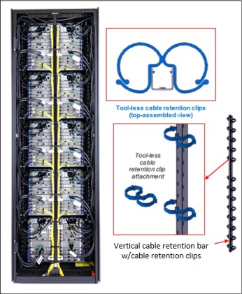
Figure 2-5 I/O cable management spine (Frame Z, rear view)
2.2 CPC drawer
The z15 Model T01 (machine type 8561) server continues the design of z14 by packaging processors in drawers. A z15 CPC drawer includes the following features:
•Five single chip modules (SCMs)
•Up to 20 Memory DIMMs
•Symmetric multiprocessor (SMP) connectivity
•Connectors to support PCIe+ Gen3 fanout cards for PCIe+ I/O drawers or coupling fanouts for coupling links to other CPCs
The z15 can include 1 - 5 CPC drawers (three in the A frame and two in the B frame). A CPC drawer and its components are shown in Figure 2-6 on page 42.

Figure 2-6 CPC drawer components (top view)
The z15 Model T01 5u CPC drawer always contains four Processor Unit (PU) SCMs, one System Controller (SC) SCM, and up to 20 memory DIMMs.
Depending on the feature, the z15 contains the following CPC components:
•The number of CPC drawers installed is driven by the following feature codes:
– FC 0655: One CPC drawer, Max34, up to 34 characterizable PUs
– FC 0656: Two CPC drawers, Max71, up to 71 characterizable PUs
– FC 0657: Three CPC drawers, Max108, up to 108 characterizable PUs
– FC 0658: Four CPC drawers, Max145, up to 145 characterizable PUs
– FC 0659: Five CPC drawers, Max190, up to 190 characterizable PUs
•The following SCMs are used:
– PU SCM uses 14nm SOI technology, 17 layers of metal, 9.2 billion transistors, core running at 5.2GHz: (with 12 cores design per PU SCM).
– SC SCM, 17 layers of metal, 9.7 billion transistors, 960 MB shared eDram L4 cache.
•Memory plugging:
– Four memory controllers per drawer (one per PU SCM)
– Each memory controller supports five DIMM slots
– Four or three memory controllers per drawer are populated (up to 20 DIMMs)
– Different memory controllers can have different size DIMMs
•Up to 12 PCIe+ Gen3 fanout slots that can host:
– 2-Port PCIe+ Gen3 I/O fanout for PCIe+ I/O drawers (always ordered and used in pairs for availability)
– ICA SR and ICA SR1.1 PCIe fanout for coupling (two ports per feature)
•Management elements: Two dual function flexible service processor (FSP) or oscillator cards (OSC) for system control and to provide system clock (N+1 redundancy).
•CPC drawer power infrastructure consists of the following components:
– Three or four Power Supply Units (PSUs) that provide power to the CPC drawer. The loss of one power supply leaves enough power to satisfy the drawer’s power requirements (N+1 redundancy). The power supplies can be concurrently removed and replaced (one at a time)
– 7x 12v distribution point-of-load (POL) that plug in slots that divide the memory banks
– 7x Voltage Regulator Modules that plug outside of the memory DIMMs
– Two Power Control cards to control the five CPC fans at the front of the CPC drawer
•Four SMP connectors that provide the CPC drawer to CPC drawer communication (NUMA).
The front view of the CPC drawer, which includes the cooling fans, FSP/OSC and bulk (power) distribution cards (BDC), is shown in Figure 2-7.

Figure 2-7 Front view of the CPC drawer
The rear view of a fully populated CPC Drawer is shown in Figure 2-8 on page 44. Dual port I/O fanouts and ICA SR adapters are plugged in specific slots for best performance and availability. Redundant power supplies and four SMP ports also are shown.

Figure 2-8 Rear view of the CPC drawer
The CPC drawer logical structure, component connections (including the PU SCMs), and the storage control SCMs are shown in Figure 2-9.
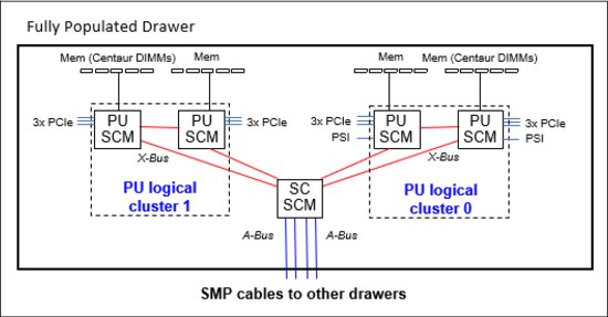
Figure 2-9 CPC drawer logical structure
Memory is connected to the SCMs through memory control units (MCUs). Up to four MCUs are available in a CPC drawer (one per PU SCM) and provide the interface to the DIMM controller. A memory controller uses five DIMM slots.
The buses are organized in the following configurations:
•The PCIe I/O buses provide connectivity for PCIe fanouts and can sustain up to 16 GBps data traffic per port.
•The X-bus provides interconnects between SC chip and PUs chips to each other, in the same logical cluster.
•The A-bus provides interconnects between SC chips (L4 cache) in different drawers by using SMP cables.
•Processor support interfaces (PSIs) are used to communicate with FSP cards for system control.
2.2.1 CPC drawer interconnect topology
The point-to-point SMP connection topology for CPC drawers is shown in Figure 2-10. Each CPC drawer communicates directly to all of the other CPC drawers SC SCM (L4 cache) by using point-to-point links.
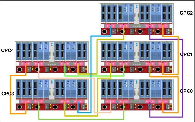
Figure 2-10 Maximum CPC drawer SMP connections (rear view)
The CPC drawers that are installed in Frame A and Frame B are populated from bottom to top.
The order of CPC drawer installation is listed in Table 2-2.
Table 2-2 CPC drawer installation order and position
|
CPC drawer1
|
CPC0
|
CPC1
|
CPC2
|
CPC3
|
CPC4
|
|
Installation order
|
First
|
Second
|
Third
|
Fourth
|
Fifth
|
|
Position in Frame A
|
A10B
|
A15B
|
A20B
|
B10B
|
B15B
|
1 CPC3 and CPC4 are factory installed only (no field MES available)
CPC drawer installation in the A frame is concurrent. Non-disruptive addition of CPC1 or CPC2 drawers is possible in the field (MES upgrade) if the reserve feature (FC 2271 or FC 2272) is present. Concurrent drawer repair requires a minimum of two drawers.
2.2.2 Oscillator4
With z15 Model T01, the oscillator card design and signal distribution scheme is new; however, the RAS strategy for redundant clock signal and dynamic switchover is unchanged. One primary OSC card and one backup are used. If the primary OSC card fails, the secondary detects the failure, takes over transparently, and continues to provide the clock signal to the CPC.
Manage System Time
On z14, HMC 2.14.1 provided a significant user experience enhancement for timing controls with the new Manage System Time task.
For simplification, the z15 (2.15.0) removes the Support Element “Sysplex/System Timer” task panels. HMC level 2.15.0 (Driver 41) is required to manage system time for z15.
|
IEEE 1588 Precision Time Protocol (PTP)1: In the future, IBM plans to introduce PTP as an external time source for IBM Z Server Time Protocol (STP) for an IBM Z Coordinated Timing Network (CTN). The initial implementation is for PTP connectivity by using the IBM Z HMC/Support Element (SE).
At that time, the use of STP CTNs for time coordination will not be changed, other than the potential to use a PTP-based external time source. Future implementation is planned to include full connectivity of an external PTP time source directly to the IBM Z CPC, and the reintroduction of the concept of a mixed CTN, with support for traditional STP and native PTP implementations. Beyond that, the goal is to enhance the role of IBM Z machines in a PTP environment that addresses the many governmental regulations and security concerns that our clients are facing.
|
1 Statements by IBM regarding its plans, directions, and intent are subject to change or withdrawal without notice at the sole discretion of IBM. The development, release, and timing of any future features or functionality described for IBM products remain at the sole discretion of IBM.
The SEs provide the Simple Network Time Protocol (SNTP) client function. When Server Time Protocol (STP) is used, the time of an STP-only Coordinated Timing Network (CTN) can be synchronized to the time that is provided by a Network Time Protocol (NTP) server. This configuration allows time-of-day (TOD) synchronization in a heterogeneous platform environment and throughout the LPARs running on the CPC.
The accuracy of an STP-only CTN is improved by using an NTP server with the PPS output signal as the External Time Source (ETS). NTP server devices with PPS output are available from several vendors that offer network timing solutions.
Consider the following points:
•A new card combines the FSP and OSC was implemented with z15. The internal physical cards (FSP and OSC) are separate, but combined as a single FRU because of a packaging design.
•Two local redundant oscillator cards are available per CPC drawer each with one PPS port.
•An enhanced precision oscillator (20 PPM5 versus 50 PPM on previous systems) is used.
•The following PPS plugging rules apply (see Figure 2-11):
– Single CPC drawer plug left and right OSC PPS coaxial connectors.
– Multi-drawer plug CPC0 left OSC PPS and CPC1 left OSC PPS coaxial connectors.
– Cables are routed from rear to front by using a pass-through hole in the frame, and under the CPC bezel by using a right-angle Bayonet Neill-Concelman (BNC) connector that provides the pulse per second (PPS) input for synchronization to an external time source with PPS output.
Cables are supplied by the customer.
– Connected PPS ports must be assigned in the Manage System Time menus on the HMC.

Figure 2-11 Recommended PPS cabling
|
Tip: STP is available as FC 1021. It is implemented in the Licensed Internal Code (LIC), and allows multiple servers to maintain time synchronization with each other and synchronization to an ETS.
For more information, see the following publications:
•Server Time Protocol Planning Guide, SG24-7280
•Server Time Protocol Implementation Guide, SG24-7281
•Server Time Protocol Recovery Guide, SG24-7380
|
2.2.3 System control
The various system elements are managed through the FSPs. An FSP is based on the IBM PowerPC® microprocessor technology.
With z15, the CPC drawer FSP card is combined with the Oscillator card in a single Field Replaceable Unit (FRU). Two combined FSP/OSC cards are used per CPC drawer.
Also, the PCIe+ I/O drawer has a new FSP. Each FSP card has one Ethernet port that connects to the internal Ethernet LANs through the internal network switches (SW1, SW2, and SW3 and SW4, if configured). The FSPs communicate with the SEs and provide a subsystem interface (SSI) for controlling components.
An overview of the system control design is shown in Figure 2-12

Figure 2-12 Conceptual overview of system control element
|
Note: The maximum z15 system configuration features four GbE switches, five CPC drawers, and up to 12 PCIe I/O drawers.
|
A typical FSP operation is to control a power supply. An SE sends a command to the FSP to start the power supply. The FSP cycles the various components of the power supply, monitors the success of each step and the resulting voltages, and reports this status to the SE.
Most SEs are duplexed (N+1), and each element has at least one FSP. Two internal Ethernet LANs and two SEs, for redundancy, and crossover capability between the LANs, are available so that both SEs can operate on both LANs.
The Hardware Management Consoles (HMCs) and SEs are connected directly to one or two Ethernet Customer LANs. One or more HMCs can be used.
2.2.4 CPC drawer power
The power for the CPC drawer is a new design. It uses the following combinations of PSUs, POL6s, VRMs, and Bulk Distribution Cards:
•PSUs: Provide AC to 12V DC bulk/standby power and are installed at the rear of the CPC. The quantity that is installed depends on the following configurations:
– Three PSUs for configurations that use BPA power
– Four PSUs for configurations that use PDU power
•POLs: Seven Point of Load N+2 Redundant cards are installed next to the Memory DIMMs.
•VRMs: seven Voltage Regulator Modules (N+2 redundancy).
•Bulk distribution card (BDC): Redundant processor power and control cards connect to the CPC trail board. The control function is powered from 12V standby that is provided by the PSU. The BDC card also includes pressure, temperature, and humidity sensors.
2.3 Single chip modules
The SCM is a multi-layer metal substrate module that holds one PU chip or an SC chip. Both PU and SC chip size is 696 mm2 (25.3 mm x 27.5 mm). Each CPC drawer has four PU SCMs (9.1 billion transistors each), and one SC SCM (9.7 billion transistors).
The two types of SCMs (PU and SC) are shown in Figure 2-13. For both SCMs, a thermal cap is placed over the chip. Each PU SCM is water cooled by way of a cold plate manifold assembly. The SC SCM is air cooled by using CPC drawer fans and heat sink.
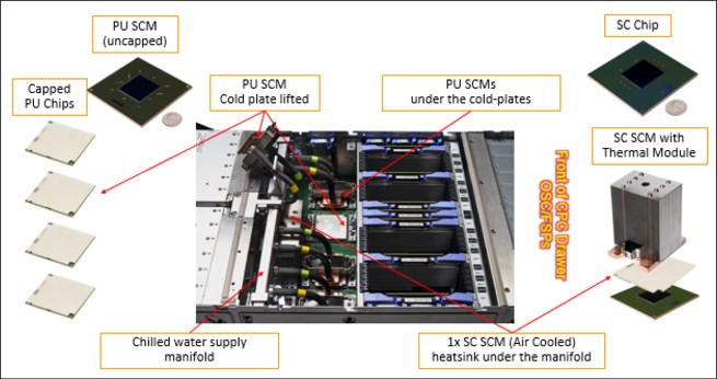
Figure 2-13 Single chip modules (PU SCM and SC SCM)
PU and SC chips use CMOS 14 nm process, 17 layers of metal, and state-of-the-art Silicon-On-Insulator (SOI) technology.
The SCMs are plugged into a socket that is part of the CPC drawer packaging. The interconnectivity between the CPC drawers is accomplished through SMP connectors and cables. Four inter-drawer connections are available on each CPC drawer. This configuration allows a multidrawer system to act as an SMP system.
2.3.1 Processor unit chip
A schematic representation of the PU chip is shown in Figure 2-14.

Figure 2-14 PU SCM floor plan
The z15 PU chip (installed as a PU SCM) is an evolution of the z14 chip design. It includes the following features and improvements:
•CMOS 14nm SOI technology
•12 core design (versus 10 for z14) with increased on-chip cache sizes
•Three PCIe Gen4 interfaces (GX bus was dropped)
•DDR4 memory controller
•Two X-buses support cluster connectivity (PU SCM-to-PU SCM and PU SCM-to-SC SCM connectivity by way of X bus).
•New EDRAM macro design with 2x macro density. Compared to z14 PU:
– L3 was increased from 128 MB to 256 MB per chip
– L2-I was increased from 2 MB to 4 MB per core
– L2-L3 protocol was changed to reduce latency
•On-chip compression accelerator (Nest Acceleration Unit - NXU)
•Further optimization of the nest-core staging
2.3.2 Processor unit (core)
Each processor unit, or core, is a superscalar and out-of-order processor that supports 10 concurrent issues to execution units in a single CPU cycle. Figure 2-15 shows the core floor plan, which contains the following units:

Figure 2-15 Processor core floor plan
•Fixed-point unit (FXU): The FXU handles fixed-point arithmetic.
•Load-store unit (LSU): The LSU contains the data cache. It is responsible for handling all types of operand accesses of all lengths, modes, and formats as defined in the z/Architecture.
•Instruction fetch and branch (IFB) (prediction) and Instruction cache and merge (ICM). These two sub units (IFB and ICM) contain the instruction cache, branch prediction logic, instruction fetching controls, and buffers. Its relative size is the result of the elaborate branch prediction.
•Instruction decode unit (IDU): The IDU is fed from the IFU buffers, and is responsible for parsing and decoding of all z/Architecture operation codes
•Translation unit (XU): The XU has a large translation lookaside buffer (TLB) and the Dynamic Address Translation (DAT) function that handles the dynamic translation of logical to physical addresses.
•Instruction sequence unit (ISU): This unit enables the out-of-order (OoO) pipeline. It tracks register names, Out-of-Order instruction dependency, and handling of instruction resource dispatch.
•Instruction fetching unit (IFU) (prediction): These units contain the instruction cache, branch prediction logic, instruction fetching controls, and buffers. Its relative size is the result of the elaborate branch prediction design.
•Recovery unit (RU): The RU keeps a copy of the complete state of the system that includes all registers, collects hardware fault signals, and manages the hardware recovery actions.
•Dedicated Co-Processor (CoP): The dedicated coprocessor is responsible for data compression and encryption functions for each core.
•Core pervasive unit (PC) for instrumentation and error collection.
•Modulo arithmetic (MA) unit: Support for Elliptic Curve Cryptography:
– Vector and Floating point Units (VFU):
• BFU: Binary floating point unit
• DFU: Decimal floating point unit
• DFx: Decimal fixed-point unit
• FPd: Floating point divide unit
• VXx: Vector fixed-point unit
• VXs: Vector string unit
• VXp: Vector permute unit
• VXm: Vector multiply unit
– L2I/L2D – Level 2 instruction/data cache
2.3.3 PU characterization
The PUs are characterized for client use. The characterized PUs can be used in general to run supported operating systems, such as z/OS, z/VM, and Linux on Z. They also can run specific workloads, such as Java, XML services, IPSec, and some Db2 workloads, or clustering functions, such as the Coupling Facility Control Code (CFCC).
The maximum number of characterizable PUs depends on the z15 CPC drawer feature code. Some PUs are characterized for system use; some are characterized for client workload use.
By default, one spare PU is available to assume the function of a failed PU. The maximum number of PUs that can be characterized for client use are listed in Table 2-3.
Table 2-3 PU characterization
|
Feature
|
CPs
|
IFLs
|
Unassigned IFLs
|
zIIPs
|
ICFs
|
IFPs
|
Std
SAPs
|
Add’l
SAPs
|
Spare
PUs
|
|
Max34
|
0-34
|
0-34
|
0-33
|
0-22
|
0-34
|
1
|
4
|
0-8
|
2
|
|
Max71
|
0-71
|
0-71
|
0-70
|
0-46
|
0-71
|
1
|
8
|
0-8
|
2
|
|
Max108
|
0-108
|
0-108
|
0-107
|
0-70
|
0-108
|
1
|
12
|
0-8
|
2
|
|
Max145
|
0-145
|
0-145
|
0-144
|
0-96
|
0-145
|
1
|
16
|
0-8
|
2
|
|
Max190
|
0-190
|
0-190
|
0-189
|
0-126
|
0-190
|
1
|
22
|
0-8
|
2
|
The rule for the CP to zIIP purchase ratio is that for every CP purchased, up to two zIIPs can be purchased. Java and XML workloads can run on zIIPs.
However, an LPAR definition can go beyond the 1:2 ratio. For example, a maximum of four physical zIIPs can be installed on a system with two physical CPs.
Converting a PU from one type to any other type is possible by using the Dynamic Processor Unit Reassignment process. These conversions occur concurrently with the system operation.
|
Note: The addition of ICFs, IFLs, zIIPs, and SAP to the z15 does not change the system capacity setting or its million service units (MSU) rating.
|
2.3.4 System Controller chip
The System Controller (SC) chip uses the CMOS 14nm SOI technology, with 17 layers of metal. It measures 25.3 x 27.5 mm, and has 9.7 billion transistors. Each CPC drawer of the system has one SC chip.
A schematic representation of the SC chip is shown in Figure 2-16. Consider the following points:
•A Bus (SC-SC off drawer): Minor changes to reflect protocol improvements and new system topology
•960 MB shared eDRAM L4 Cache
•L4 Directory is built with eDRAM
•New L4 Cache Management: Ratio of L3 to L4 cache capacity is increasing

Figure 2-16 SC chip floor plan
2.3.5 Cache level structure
The cache structure comparison between CPC drawers on z14 and z15 is shown in Figure 2-17.

Figure 2-17 Cache structure comparison: z14 versus z15
2.4 PCIe+ I/O drawer
As shown in Figure 2-18 on page 55, each PCIe+ I/O drawer has 16 slots each to support the PCIe I/O infrastructure with a bandwidth of 16 GBps and includes the following features:
•A total of 16 I/O cards are spread over two I/O domains (0 and 1):
– Each I/O slot reserves four PCHIDs.
– Left side slots are numbered LG01-LG10 and right side slots are numbered LG11-LG20 from the rear of the rack. A location and LED identifier panel is at the center of the drawer.
– New with z15 Model T01, the numbering of the PCHIDs is not related to a fixed location in a frame as with previous generations of Z systems. Instead, the first configured I/O location starts with PCHID 100 and continues the incremental sequence to the next configured PCIe I/O drawer. For more information about examples of the various configurations, see Appendix D, “Frame configurations” on page 509.
•Two PCIe+ switch cards provide connectivity to the PCIe+ Gen3 fanouts that are installed in the CPC drawers.
•Each I/O drawer domain has four dedicated support partitions (two per domain) to manage the native PCIe cards.
•Two Flexible Support Processor (FSP) cards are used to control the drawer function.
•Redundant N+1 power supplies (two) are mounted on the rear and redundant blowers (six) are mounted on the front.

Figure 2-18 PCIe I/O drawer front and rear view
The following configuration examples and how the configurations are different with the power selection, number of CPC drawers and I/O features ordered, the layout of the PCIe+ I/O drawers, and PCHID numbering are shown in Figure 2-19:

Figure 2-19 Configuration examples with PCHID numbering
•The first, a single frame system, ordered with PDU power, radiator cooling, one CPC drawer, and greater than 32 I/O features to drive three I/O drawers.
PCHID numbering is consecutive from top to bottom.
•The second, a three frame system, ordered with PDU power, radiator cooling, four CPC drawers, and greater than 128 I/O features to drive nine I/O drawers.
PCHID numbering starts in the A-frame, resumes in the B-frame from top down, and continues to the Z-frame working from the bottom up.
•The third, a two frame system, ordered with BPA, IBF power options, radiator cooling, one CPC drawer, two reserved CPC drawer slots for future CPC drawer add MES, and greater than 64 I/O features to drive five I/O drawers
PCHID numbering starts in the Z-frame, from the bottom and working up.
Consideration for PCHID identification:
In previous PCIe I/O drawers (introduced with zEC12), the orientation of the I/O features were vertical. For z15, the orientation of the PCIe features is horizontal, and the top of the card is now closest to the center of the drawer for the left and right side of the drawer.
The vertical card collapsed horizontal and the awareness of the port and PCHID layout where the top of the adapter (port D1) is closest to the location panel on both sides of the drawer are shown in Figure 2-20.

Figure 2-20 I/O feature orientation in PCIe I/O drawer (rear view)
|
Note: The CHPID Mapping Tool (available on ResourceLink) can be used to print a CHPID Report that displays the drawer and PCHID/CHPID layout.
|
2.5 Memory
The maximum physical memory size is directly related to the number of CPC drawers in the system. Each CPC drawer can contain up to 8 TB of customer memory, for a total of 40 TB of memory per system.
The minimum and maximum memory sizes that you can order for each z15 feature are listed in Table 2-4.
Table 2-4 Purchased Memory (Memory available for assignment to LPARs)
|
Feature
|
# of CPC drawers
|
Customer memory GB
|
Flexible memory GB
|
|
Max34
|
1
|
512 - 7936
|
NA
|
|
Max71
|
2
|
512 - 16128
|
512 - 7936
|
|
Max108
|
3
|
512 - 24320
|
512 - 16128
|
|
Max145
|
4
|
512 - 32512
|
512 - 24320
|
|
Max190
|
5
|
512 - 40704
|
512 - 32512
|
The following memory types are available:
•Purchased: Memory that is available for assignment to LPARs.
•Hardware System Area (HSA): Standard 256 GB of addressable memory for system use outside of customer memory.
•Standard: Provides minimum physical memory that is required to hold customer purchase memory plus 256 GB HSA.
•Flexible: Provides more physical memory that is needed to support that activation of base customer memory and HSA on a multiple CPC drawer z15 with one drawer out of service (concurrent drawer replacement; not available on Max34 feature).
|
Note: The Plan Ahead Memory feature is not offered with a new order z15 system. The Plan Ahead Memory feature that is available on z13 or z14 can be carried forward to z15.
|
The memory granularity, which is based on the installed customer memory, is listed in Table 2-5.
Table 2-5 Customer offering memory increments
|
Memory increment (GB)
|
Offered memory sizes (GB)
|
|
64
|
512 - 768
|
|
128
|
896 - 2048
|
|
256
|
2304 - 3840
|
|
512
|
4352 - 17152
|
|
1024
|
18176 - 32512
|
|
2048
|
34560 - 40704
|
2.5.1 Memory subsystem topology
The z15 memory subsystem uses high-speed, differential-ended communications memory channels to link a host memory to the main memory storage devices.
The CPC drawer memory topology of a z15 server is shown in Figure 2-21.

Figure 2-21 CPC drawer memory topology at maximum configuration
Consider the following points regarding the topology:
•One MCU per processor chip with five memory channels, one DIMM per channel (no DIMM cascading) is used.
•The fifth channel in each MCU enables memory to be implemented as a Redundant Array of Independent Memory (RAIM). This technology features significant error detection and correction capabilities. Bit, lane, DRAM, DIMM, socket, and complete memory channel failures can be detected and corrected, including many types of multiple failures. Therefore, RAIM takes 20% of DIMM capacity. (No non-RAIM option is available.)
•DIMM sizes used are 32, 64, 128, 256 and 512 GB with five DIMMs of the same size included in a memory feature (160, 320, 640, 1280 and 2560 GB RAIM array size, respectively).
•Three or four features (15 or 20 DIMMs) are plugged in each drawer.
•Features with different DIMMs sizes can be mixed in the same drawer.
•The five DIMMs per MCU must be the same size.
•Addressable memory is required for partitions and HSA.
2.5.2 Redundant array of independent memory
The z15 server uses the RAIM technology. The RAIM design detects and recovers from failures of dynamic random access memory (DRAM), sockets, memory channels, or DIMMs.
The RAIM design requires the addition of one memory channel that is dedicated for reliability, availability, and serviceability (RAS).
The five channel RAIM Memory Controller overview is shown in Figure 2-22.

Figure 2-22 Five channel RAIM Memory Controller Overview
The fifth channel in each MCU enables memory to be implemented as a RAIM. This technology features significant error detection and correction capabilities. Bit, lane, DRAM, DIMM, socket, and complete memory channel failures can be detected and corrected, including many types of multiple failures. Therefore, RAIM takes 20% of DIMM capacity (a non-RAIM option is not available).
The RAIM design provides the following layers of memory recovery:
•ECC with 90B/64B Reed Solomon code.
•DRAM failure, with marking technology in which two DRAMs can be marked and no half sparing is needed. A call for replacement occurs on the third DRAM failure.
•Lane failure with CRC retry, data-lane sparing, and clock-RAIM with lane sparing.
•DIMM failure (discrete components and VTT Reg) with CRC retry, data-lane sparing, and clock-RAIM with lane sparing.
•DIMM controller ASIC failure.
•Channel failure started RAIM recovery.
2.5.3 Memory configurations
Memory sizes in each CPC drawer do not have to be similar. Different CPC drawers can contain different amounts of memory. The 10 (10-19) drawer memory configurations that are supported are listed in Table 2-6. Each CPC drawer is included from manufacturing with one of these memory configurations. Total physical memory includes RAIM (20%).
Table 2-6 Drawer memory plugging configurations
|
CFG #
|
Physical
memory
GB
|
32 GB
#DIMMs
|
64 GB
#DIMMs
|
128 GB
#DIMMs
|
256 GB
#DIMMs
|
512 GB
#DIMMs
|
-RAIM
GB
|
-HSA
GB
|
|
10
|
640
|
20
|
0
|
0
|
0
|
0
|
512
|
256
|
|
11
|
960
|
10
|
10
|
0
|
0
|
0
|
768
|
512
|
|
12
|
1280
|
0
|
20
|
0
|
0
|
0
|
1024
|
768
|
|
13
|
1600
|
0
|
10
|
10
|
0
|
0
|
1536
|
1280
|
|
14
|
1920
|
0
|
0
|
20
|
0
|
0
|
2048
|
1792
|
|
15
|
3840
|
0
|
0
|
10
|
10
|
0
|
3072
|
2816
|
|
16
|
5120
|
0
|
0
|
0
|
20
|
0
|
4096
|
3840
|
|
17
|
7680
|
0
|
0
|
0
|
10
|
10
|
6144
|
5888
|
|
18
|
10240
|
0
|
0
|
0
|
0
|
20
|
8192
|
7936
|
|
19
|
480
|
15
|
0
|
0
|
0
|
0
|
384
|
128
|
Consider the following points:
•A CPC drawer always contains a minimum of 15 32GB DIMMs as listed in drawer configuration number 19 in Table 2-6 on page 59.
•A CPC drawer can have more memory installed than is enabled. The amount of memory that can be enabled by the client is the total physically installed memory minus the RAIM amount (20%) and minus the 256 GB of HSA memory.
•A CPC drawer can have available unused memory, which can be ordered as a memory upgrade and enabled by LIC-CC without DIMM changes.
•DIMM changes require a disruptive power-on reset (POR) on z15 with a single CPC drawer. DIMM changes can be done concurrently on z15 models with multiple CPC drawers using Enhanced Drawer Availability (EDA).
DIMM plugging for the configurations in each CPC drawer do not have to be similar. Each memory 5 slot DIMM bank must have the same DIMM size; however, a drawer can have a mix of DIMM banks. Table 2-7 lists the memory population by DIMM bank for the 15 configurations that are listed in Table 2-6 on page 59.
As an example, for configuration #14, memory positions MD06-MD10 are populated with five 128 GB DIMMS.
Table 2-7 Memory Population by DIMM Bank
|
CFG #
|
MD01-MD05
|
MD06-MD10
|
MD11-MD15
|
MD16-MD20
|
Physical
|
Total -RAIM
|
Total- RAIM+HSA
|
|
10
|
32
|
32
|
32
|
32
|
640
|
512
|
256
|
|
11
|
64
|
32
|
32
|
64
|
960
|
768
|
512
|
|
12
|
64
|
64
|
64
|
64
|
1280
|
1024
|
768
|
|
13
|
128
|
64
|
64
|
128
|
1920
|
1536
|
1280
|
|
14
|
128
|
128
|
128
|
128
|
2560
|
2048
|
1792
|
|
15
|
256
|
128
|
128
|
256
|
3840
|
3072
|
2816
|
|
16
|
256
|
256
|
256
|
256
|
5120
|
4096
|
3840
|
|
17
|
512
|
256
|
256
|
512
|
7680
|
6144
|
5888
|
|
18
|
512
|
512
|
512
|
512
|
10240
|
8192
|
7936
|
|
19
|
32
|
32
|
32
|
|
480
|
384
|
128
|
The support element View Hardware Configuration task can be used to determine the size and quantity of the memory plugged in each drawer. Figure 2-23 shows an example of configuration number 16 from the previous tables, and displays the location and description of the installed memory modules.

Figure 2-23 View Hardware Configuration task on the Support Element
Figure 2-24 shows the CPC drawer and DIMM locations for a z15.

Figure 2-24 CPC drawer and DIMM locations for a z15
Table 2-8 lists the physical memory plugging configurations by feature code from manufacturing when the system is ordered. Consider the following points:
•The CPC drawer columns for the specific feature contain the Memory Plug Drawer Configuration number that us referenced in Table 2-6 on page 59 and the Population by DIMM Bank that is listed in Table 2-7 on page 60.
•Dial Max indicates the maximum memory that can be enabled by way of the LICC concurrent upgrade.
If more storage is ordered by using other feature codes, such as Virtual Flash Memory, or Flexible Memory, the extra storage is installed and plugged as necessary.
For example, a customer orders FC 1528 that features 1920 GB memory and Max145 (4 CPC drawers). The drawer configurations include the following components:
•CPC0 (768GB), CPC3 (768GB) - Configuration #11 (from Table 2-6 on page 59)
•CPC1 (384GB), CPC2 (384GB) - Configuration #19
•Total 768 + 768 + 384 + 384 - 256 HSA= 2048GB (Dial Max)
Table 2-8 Memory features and physical plugging
|
Feature
Code
|
Increments
|
Customer
Memory
Increments
|
Max34
|
Max71
|
Max108
|
Max145
|
Max190
|
|||||||||||||||
|
Drawer CPC0
|
Dial Max
|
Drawer CPC0
|
Drawer CPC1
|
Dial Max
|
Drawer CPC0
|
Drawer CPC1
|
Drawer CPC2
|
Dial Max
|
Drawer CPC0
|
Drawer CPC1
|
Drawer CPC2
|
Drawer CPC3
|
Dial Max
|
Drawer CPC0
|
Drawer CPC1
|
Drawer CPC2
|
Drawer CPC3
|
Drawer CPC4
|
Dial Max
|
|||
|
1515
|
64
|
512
|
12
|
768
|
11
|
19
|
896
|
11
|
19
|
19
|
1280
|
11
|
19
|
19
|
19
|
1664
|
11
|
19
|
19
|
19
|
19
|
2048
|
|
1516
|
576
|
12
|
768
|
11
|
19
|
896
|
11
|
19
|
19
|
1280
|
11
|
19
|
19
|
19
|
1664
|
11
|
19
|
19
|
19
|
19
|
2048
|
|
|
1517
|
640
|
12
|
768
|
11
|
19
|
896
|
11
|
19
|
19
|
1280
|
11
|
19
|
19
|
19
|
1664
|
11
|
19
|
19
|
19
|
19
|
2048
|
|
|
1518
|
704
|
12
|
768
|
11
|
19
|
896
|
11
|
19
|
19
|
1280
|
11
|
19
|
19
|
19
|
1664
|
11
|
19
|
19
|
19
|
19
|
2048
|
|
|
1519
|
768
|
12
|
768
|
11
|
19
|
896
|
11
|
19
|
19
|
1280
|
11
|
19
|
19
|
19
|
1664
|
11
|
19
|
19
|
19
|
19
|
2048
|
|
|
1520
|
128
|
896
|
13
|
1280
|
11
|
19
|
896
|
11
|
19
|
19
|
1280
|
11
|
19
|
19
|
19
|
1664
|
11
|
19
|
19
|
19
|
19
|
2048
|
|
1521
|
1024
|
13
|
1280
|
12
|
19
|
1152
|
11
|
19
|
19
|
1280
|
11
|
19
|
19
|
19
|
1664
|
11
|
19
|
19
|
19
|
19
|
2048
|
|
|
1522
|
1152
|
13
|
1280
|
12
|
19
|
1152
|
11
|
19
|
19
|
1280
|
11
|
19
|
19
|
19
|
1664
|
11
|
19
|
19
|
19
|
19
|
2048
|
|
|
1523
|
1280
|
13
|
1280
|
12
|
11
|
1536
|
11
|
19
|
19
|
1280
|
11
|
19
|
19
|
19
|
1664
|
11
|
19
|
19
|
19
|
19
|
2048
|
|
|
1524
|
1408
|
14
|
1792
|
12
|
11
|
1536
|
11
|
19
|
11
|
1664
|
11
|
19
|
19
|
19
|
1664
|
11
|
19
|
19
|
19
|
19
|
2048
|
|
|
1525
|
1536
|
14
|
1792
|
12
|
11
|
1536
|
11
|
19
|
11
|
1664
|
11
|
19
|
19
|
19
|
1664
|
11
|
19
|
19
|
19
|
19
|
2048
|
|
|
1526
|
1664
|
14
|
1792
|
12
|
12
|
1792
|
11
|
19
|
11
|
1664
|
11
|
19
|
19
|
19
|
1664
|
11
|
19
|
19
|
19
|
19
|
2048
|
|
|
1527
|
1792
|
14
|
1792
|
12
|
12
|
1792
|
11
|
11
|
11
|
2048
|
11
|
19
|
19
|
11
|
2048
|
11
|
19
|
19
|
19
|
19
|
2048
|
|
|
1528
|
1920
|
15
|
2816
|
13
|
13
|
2816
|
11
|
11
|
11
|
2048
|
11
|
19
|
19
|
11
|
2048
|
11
|
19
|
19
|
19
|
19
|
2048
|
|
|
1529
|
2048
|
15
|
2816
|
13
|
13
|
2816
|
11
|
11
|
11
|
2048
|
11
|
19
|
19
|
11
|
2048
|
11
|
19
|
19
|
19
|
19
|
2048
|
|
|
1530
|
256
|
2304
|
15
|
2816
|
13
|
13
|
2816
|
12
|
11
|
12
|
2560
|
11
|
11
|
11
|
11
|
2816
|
11
|
11
|
19
|
19
|
11
|
2816
|
|
1531
|
2560
|
15
|
2816
|
13
|
13
|
2816
|
12
|
11
|
12
|
2560
|
11
|
11
|
11
|
11
|
2816
|
11
|
11
|
19
|
19
|
11
|
2816
|
|
|
1532
|
2816
|
15
|
2816
|
13
|
13
|
2816
|
12
|
12
|
12
|
2816
|
11
|
11
|
11
|
11
|
2816
|
11
|
11
|
19
|
19
|
11
|
2816
|
|
|
1533
|
3072
|
16
|
3840
|
14
|
14
|
3840
|
13
|
12
|
13
|
3840
|
12
|
11
|
11
|
12
|
3328
|
11
|
11
|
11
|
11
|
11
|
3584
|
|
|
1534
|
3328
|
16
|
3840
|
14
|
14
|
3840
|
13
|
12
|
13
|
3840
|
12
|
11
|
11
|
12
|
3328
|
11
|
11
|
11
|
11
|
11
|
3584
|
|
|
1535
|
3584
|
16
|
3840
|
14
|
14
|
3840
|
13
|
12
|
13
|
3840
|
12
|
12
|
12
|
12
|
3840
|
11
|
11
|
11
|
11
|
11
|
3584
|
|
|
1536
|
3840
|
16
|
3840
|
14
|
14
|
3840
|
13
|
12
|
13
|
3840
|
12
|
12
|
12
|
12
|
3840
|
12
|
12
|
11
|
11
|
12
|
4352
|
|
|
1537
|
512
|
4352
|
17
|
5888
|
15
|
15
|
5888
|
13
|
13
|
13
|
4352
|
13
|
12
|
12
|
13
|
4864
|
12
|
12
|
11
|
11
|
12
|
4352
|
|
1538
|
4864
|
17
|
5888
|
15
|
15
|
5888
|
14
|
13
|
14
|
5376
|
13
|
12
|
12
|
13
|
4864
|
12
|
12
|
12
|
12
|
12
|
4864
|
|
|
1539
|
5376
|
17
|
5888
|
15
|
15
|
5888
|
14
|
13
|
14
|
5376
|
13
|
13
|
13
|
13
|
5888
|
13
|
12
|
12
|
12
|
13
|
5888
|
|
|
1540
|
5888
|
17
|
5888
|
15
|
15
|
5888
|
14
|
14
|
14
|
5888
|
13
|
13
|
13
|
13
|
5888
|
13
|
12
|
12
|
12
|
13
|
5888
|
|
|
1541
|
6400
|
18
|
7936
|
16
|
16
|
7936
|
15
|
14
|
15
|
7936
|
14
|
13
|
13
|
14
|
6912
|
13
|
13
|
12
|
13
|
13
|
6912
|
|
|
1542
|
6912
|
18
|
7936
|
16
|
16
|
7936
|
15
|
14
|
15
|
7936
|
14
|
13
|
13
|
14
|
6912
|
13
|
13
|
12
|
13
|
13
|
6912
|
|
|
1543
|
7424
|
18
|
7936
|
16
|
16
|
7936
|
15
|
14
|
15
|
7936
|
14
|
14
|
14
|
14
|
7936
|
13
|
13
|
13
|
13
|
13
|
7424
|
|
|
1544
|
7936
|
18
|
7936
|
16
|
16
|
7936
|
15
|
14
|
15
|
7936
|
14
|
14
|
14
|
14
|
7936
|
14
|
13
|
13
|
13
|
14
|
8448
|
|
|
1545
|
8448
|
|
|
17
|
17
|
12032
|
15
|
15
|
15
|
8960
|
15
|
14
|
14
|
15
|
9984
|
14
|
13
|
13
|
13
|
14
|
8448
|
|
|
1546
|
8960
|
|
|
17
|
17
|
12032
|
15
|
15
|
15
|
8960
|
15
|
14
|
14
|
15
|
9984
|
14
|
14
|
13
|
14
|
14
|
9472
|
|
|
1547
|
9472
|
|
|
17
|
17
|
12032
|
16
|
15
|
16
|
11008
|
15
|
14
|
14
|
15
|
9984
|
14
|
14
|
13
|
14
|
14
|
9472
|
|
|
1548
|
9984
|
|
|
17
|
17
|
12032
|
16
|
15
|
16
|
11008
|
15
|
14
|
14
|
15
|
9984
|
14
|
14
|
14
|
14
|
14
|
9984
|
|
|
1549
|
10496
|
|
|
17
|
17
|
12032
|
16
|
15
|
16
|
11008
|
15
|
15
|
15
|
15
|
12032
|
15
|
14
|
14
|
14
|
15
|
12032
|
|
|
1550
|
11008
|
|
|
17
|
17
|
12032
|
16
|
15
|
16
|
11008
|
15
|
15
|
15
|
15
|
12032
|
15
|
14
|
14
|
14
|
15
|
12032
|
|
|
1551
|
11520
|
|
|
17
|
17
|
12032
|
16
|
16
|
16
|
12032
|
15
|
15
|
15
|
15
|
12032
|
15
|
14
|
14
|
14
|
15
|
12032
|
|
|
1552
|
12032
|
|
|
17
|
17
|
12032
|
16
|
16
|
16
|
12032
|
15
|
15
|
15
|
15
|
12032
|
15
|
14
|
14
|
14
|
15
|
12032
|
|
|
1553
|
12544
|
|
|
18
|
18
|
16128
|
17
|
16
|
17
|
16128
|
16
|
15
|
15
|
16
|
14080
|
15
|
14
|
14
|
15
|
15
|
13056
|
|
|
1554
|
13056
|
|
|
18
|
18
|
16128
|
17
|
16
|
17
|
16128
|
16
|
15
|
15
|
16
|
14080
|
15
|
14
|
14
|
15
|
15
|
13056
|
|
|
1555
|
13568
|
|
|
18
|
18
|
16128
|
17
|
16
|
17
|
16128
|
16
|
15
|
15
|
16
|
14080
|
15
|
15
|
15
|
15
|
15
|
15104
|
|
|
1556
|
14080
|
|
|
18
|
18
|
16128
|
17
|
16
|
17
|
16128
|
16
|
15
|
15
|
16
|
14080
|
15
|
15
|
15
|
15
|
15
|
15104
|
|
|
1557
|
14592
|
|
|
18
|
18
|
16128
|
17
|
16
|
17
|
16128
|
16
|
16
|
16
|
16
|
16128
|
15
|
15
|
15
|
15
|
15
|
15104
|
|
|
1558
|
15104
|
|
|
18
|
18
|
16128
|
17
|
16
|
17
|
16128
|
16
|
16
|
16
|
16
|
16128
|
15
|
15
|
15
|
15
|
15
|
15104
|
|
|
1559
|
15616
|
|
|
18
|
18
|
16128
|
17
|
16
|
17
|
16128
|
16
|
16
|
16
|
16
|
16128
|
16
|
15
|
15
|
15
|
16
|
17152
|
|
|
1560
|
16128
|
|
|
18
|
18
|
16128
|
17
|
16
|
17
|
16128
|
16
|
16
|
16
|
16
|
16128
|
16
|
15
|
15
|
15
|
16
|
17152
|
|
|
1561
|
16640
|
|
|
|
|
|
17
|
17
|
17
|
18176
|
17
|
16
|
16
|
17
|
20224
|
16
|
15
|
15
|
15
|
16
|
17152
|
|
|
1562
|
17152
|
|
|
|
|
|
17
|
17
|
17
|
18176
|
17
|
16
|
16
|
17
|
20224
|
16
|
15
|
15
|
15
|
16
|
17152
|
|
|
1563
|
1024
|
18176
|
|
|
|
|
|
17
|
17
|
17
|
18176
|
17
|
16
|
16
|
17
|
20224
|
16
|
16
|
16
|
15
|
16
|
19200
|
|
1564
|
19200
|
|
|
|
|
|
18
|
17
|
18
|
22272
|
17
|
16
|
16
|
17
|
20224
|
16
|
16
|
16
|
15
|
16
|
19200
|
|
|
1565
|
20224
|
|
|
|
|
|
18
|
17
|
18
|
22272
|
17
|
16
|
16
|
17
|
20224
|
16
|
16
|
16
|
16
|
16
|
20224
|
|
|
1566
|
21248
|
|
|
|
|
|
18
|
17
|
18
|
22272
|
17
|
17
|
17
|
17
|
24320
|
17
|
16
|
16
|
16
|
17
|
24320
|
|
|
1567
|
22272
|
|
|
|
|
|
18
|
17
|
18
|
22272
|
17
|
17
|
17
|
17
|
24320
|
17
|
16
|
16
|
16
|
17
|
24320
|
|
|
1568
|
23296
|
|
|
|
|
|
18
|
18
|
18
|
24320
|
17
|
17
|
17
|
17
|
24320
|
17
|
16
|
16
|
16
|
17
|
24320
|
|
|
1569
|
24320
|
|
|
|
|
|
18
|
18
|
18
|
24320
|
17
|
17
|
17
|
17
|
24320
|
17
|
16
|
16
|
16
|
17
|
24320
|
|
|
1570
|
25344
|
|
|
|
|
|
|
|
|
|
18
|
17
|
17
|
18
|
28416
|
17
|
17
|
16
|
16
|
17
|
26368
|
|
|
1571
|
26368
|
|
|
|
|
|
|
|
|
|
18
|
17
|
17
|
18
|
28416
|
17
|
17
|
16
|
16
|
17
|
26368
|
|
|
1572
|
27392
|
|
|
|
|
|
|
|
|
|
18
|
17
|
17
|
18
|
28416
|
17
|
17
|
17
|
16
|
17
|
28416
|
|
|
1573
|
28416
|
|
|
|
|
|
|
|
|
|
18
|
17
|
17
|
18
|
28416
|
17
|
17
|
17
|
16
|
17
|
28416
|
|
|
1574
|
29440
|
|
|
|
|
|
|
|
|
|
18
|
18
|
18
|
18
|
32512
|
17
|
17
|
17
|
17
|
17
|
30464
|
|
|
1575
|
30464
|
|
|
|
|
|
|
|
|
|
18
|
18
|
18
|
18
|
32512
|
17
|
17
|
17
|
17
|
17
|
30464
|
|
|
1576
|
31488
|
|
|
|
|
|
|
|
|
|
18
|
18
|
18
|
18
|
32512
|
18
|
17
|
17
|
17
|
18
|
34560
|
|
|
1577
|
32512
|
|
|
|
|
|
|
|
|
|
18
|
18
|
18
|
18
|
32512
|
18
|
17
|
17
|
17
|
18
|
34560
|
|
|
1578
|
2048
|
34560
|
|
|
|
|
|
|
|
|
|
|
|
|
|
|
18
|
17
|
17
|
17
|
18
|
34560
|
|
1579
|
36608
|
|
|
|
|
|
|
|
|
|
|
|
|
|
|
18
|
18
|
17
|
17
|
18
|
36608
|
|
|
1580
|
38656
|
|
|
|
|
|
|
|
|
|
|
|
|
|
|
18
|
18
|
18
|
17
|
18
|
38656
|
|
|
1581
|
40704
|
|
|
|
|
|
|
|
|
|
|
|
|
|
|
18
|
18
|
18
|
18
|
18
|
40704
|
|
2.5.4 Memory upgrades
Memory upgrades can be ordered and enabled by LIC, upgrading the DIMM cards, adding DIMM cards, or adding a CPC drawer.
For a model upgrade that results in the addition of a CPC drawer, the minimum memory increment is added to the system. Each CPC drawer has a minimum physical memory size of 480 GB.
During a model upgrade, adding a CPC drawer is a concurrent operation. Adding physical memory to the added drawer is also concurrent. If all or part of the added memory is enabled for use, it might become available to an active LPAR if the partition includes defined reserved storage. (For more information, see 3.7.3, “Reserved storage” on page 141.) Alternatively, the added memory can be used by a defined LPAR that is activated after the memory is added.
|
Note: Memory downgrades within a z15 are not supported. Feature downgrades (removal of a CPC quantity feature) are not supported.
|
2.5.5 Drawer replacement and memory
With Enhanced Drawer Availability (EDA), which is supported for z15, sufficient resources must be available to accommodate resources that are rendered unavailable when a CPC drawer is removed for upgrade or repair. For more information, see 2.7.1, “Redundant I/O interconnect” on page 70.
Removing a CPC drawer often results in removing active memory. With the flexible memory option, removing the affected memory and reallocating its use elsewhere in the system is possible. For more information, see 2.5.7, “Flexible Memory Option”. This process requires more available memory to compensate for the memory that is lost with the removal of the drawer.
2.5.6 Virtual Flash Memory
IBM Virtual Flash Memory (VFM) FC 0643 replaces the Flash Express features (0402 and 0403) that were available on the IBM z13s. It offers up to 6.0 TB of virtual flash memory in 512 GB (0.5 TB) increments for improved application availability and to handle paging workload spikes.
No application changes are required to change from IBM Flash Express to VFM. Consider the following points:
•Dialed memory + VFM = total hardware plugged
•Dialed memory + VFM + Flex memory option = total hardware plugged
•VFM is offered in 0.5 TB increment size; VFM for z15 is FC 0643 - Min=0, Max=12
VFM is designed to help improve availability and handling of paging workload spikes when z/OS V2.1, V2.2, V2.3, or V2.4 is run. With this support, z/OS is designed to help improve system availability and responsiveness by using VFM across transitional workload events, such as market openings and diagnostic data collection. z/OS is also designed to help improve processor performance by supporting middleware use of pageable large (1 MB) pages.
VFM can also be used by coupling facility images to provide extended capacity and availability for workloads that are use IBM WebSphere MQ Shared Queues structures. The use of VFM can improve availability by reducing latency from paging delays that can occur at the start of the workday or during other transitional periods. It is also designed to help eliminate delays that can occur when collecting diagnostic data.
VFM can help organizations meet their most demanding service level agreements and compete more effectively. VFM is easy to configure in the LPAR Image Profile and provides rapid time to value.
2.5.7 Flexible Memory Option
With the Flexible Memory Option, more physical memory is supplied to support the activation of the actual purchased memory entitlement in a single CPC drawer that is out of service during activation (POR), or in a scheduled concurrent drawer upgrade (memory add) or drawer maintenance (n+1 repair) with the use of enhanced drawer availability.
When you order memory, you can request extra flexible memory. The extra physical memory, if required, is calculated by the configuration and priced accordingly.
The hardware required is pre-plugged based on a target capacity specified by the customer. This pre-plugged hardware is enabled by using an LICCC order that is placed by the customer when they determine more memory capacity is needed.
The flexible memory sizes that are available for the z15 are listed in Table 2-9.
Table 2-9 Flexible memory offering
|
Feature Code
|
Increment
|
Minimum
|
Maximum
|
|
1951
|
32GB Flex Memory
|
0
|
250
|
|
1952
|
64GB Flex Memory
|
0
|
250
|
|
1953
|
256GB Flex Memory
|
0
|
250
|
|
1954
|
64GB Virtual Flash Memory Flex Memory
|
0
|
1
|
2.6 Reliability, availability, and serviceability
IBM Z servers continue to deliver enterprise class RAS with IBM z15. The main philosophy behind RAS is about preventing or tolerating (masking) outages. It is also about providing the necessary instrumentation (in hardware, LIC and microcode, and software) to capture or collect the relevant failure information to help identify an issue without requiring a reproduction of the event. These outages can be planned or unplanned. Planned and unplanned outages can include the following situations (examples are not related to the RAS features of IBM Z servers):
•A planned outage because of the addition of physical processor capacity or memory
•A planned outage because of the addition of I/O cards
•An unplanned outage because of a failure of a power supply
•An unplanned outage because of a memory failure
The IBM Z hardware has decades of intense engineering behind it, which results in a robust and reliable platform. The hardware has many RAS features that are built into it. For more information, see Chapter 9, “Reliability, availability, and serviceability” on page 381.
2.6.1 RAS in the CPC memory subsystem
Patented error correction technology in the memory subsystem continues to provide the most robust error correction from IBM to date. Two full DRAM failures per rank can be spared and a third full DRAM failure can be corrected.
DIMM level failures, including components, such as the memory controller application-specific integrated circuit (ASIC), power regulators, clocks, and system board, can be corrected. Memory channel failures, such as signal lines, control lines, and drivers and receivers on the MCM, can be corrected.
Upstream and downstream data signals can be spared by using two spare wires on the upstream and downstream paths. One of these signals can be used to spare a clock signal line (one upstream and one downstream). The following improvements were also added in the z15 server:
•No cascading of memory DIMMs
•Independent channel recovery
•Double tabs for clock lanes
•Separate replay buffer per channel
•Hardware driven lane soft error rate (SER) and sparing
2.6.2 General z15 RAS features
The z15 server includes the following RAS features:
•The z15 server provides a true N+2 pumps and N+1 fans for the cooling function for the radiator-cooled (air-cooled) model and N+1 (fully redundant) cooling function for the water-cooled model.
•The Power/Thermal Subsystem is new for z15. It uses switchable, intelligent Power Distribution Units (PDUs) or Bulk Power Assemblies.
•Redundant (N+1), number of PDUs (up to four pairs) or BPAs, which are configuration-dependent (2 or 4)
•CPC drawer is packaged to fit in the 19-inch frame. CPC drawer power and cooling includes the following components:
– PSUs: AC to 12V bulk/standby (N+1 redundant). PSU fans are not separate FRUs CPC drawers have 3 PSUs for BPA-based configurations or 4 PSUs for PDU-based configurations.
– POLs: N+2 Phase and Master Redundant and are available in quantities of up to 6.
– VRM sticks7: Derivative of z13s design (N+2 Phase and Master redundancy) and are available in quantities of 7.
– Power Control Card: New power control card to control CPC fans (N+1 redundant) and are available in quantities of 2.
– Fans: Drawer has five fans and are N+1 redundant.
– FSP/OSCs: Redundant (N+1).
•PU SCMs are all water-cooled. The SC SCM is air-cooled and uses a heat sink (same as z14 M0x).
•The PCIe+ I/O drawer power supplies for the z15 server are also based on the N+1 design. The second power supply can maintain operations and avoid an unplanned outage of the system.
•N+2 redundant environmental sensors (ambient temperature, relative humidity, and air density8).
The internal intelligent Power Distribution Unit (iPDU, or PDU) provide the following capabilities:
•Individual outlet control by way of Ethernet:
– Provide a System Reset capability
– Power cycle an SE if a hang occurs
– Verify a power cable at installation
•System Reset Function:
– No EPO switch is available on the z15. This function provides a means to put a server into a known state similar to past total power reset.
– This function does not provide the option to power down and keep the power down to the system. The power must be unplugged or the customer-supplied power is turned off at the panel.
•Other characteristics:
– PDU Firmware can be concurrently updated
– Concurrently repairable
– Power redundancy check
•Cable verification test by way of PDU:
– By power cycling individual iPDU outlets, the system can verify proper cable connectivity
– Power cable test runs during system Power On
– Runs at system Installation and at every system Power On until the test passes
•PCIe service enhancements:
– Mandatory end-to-end cyclic redundancy check (ECRC)
– Customer operation code separate from maintenance code
– Native PCIe firmware stack that is running on the integrated firmware processor (IFP) to manage isolation and recovery
The power service and control network (PSCN) is used to control and monitor the elements in the system and include the following components:
•Ethernet Top of Rack (TOR) switches provide the internal PSCN connectivity:
– Switches are redundant (N+1)
– Concurrently maintainable
– Each switch has one integrated power supply
– FSPs are cross wired to the Ethernet switches
•Redundant SEs
Each SE has two power supplies (N+1) and input power is cross-coupled from the PDUs.
•Concurrent CPC upgrades
CPC1to CPC1 + CPC2 and CPC1 + CPC2 to CPC1+CPC2+CPC3 (with Reserve FC 2271 or 2272)
•All PCIe+ I/O drawer MESs are concurrent
•All LICC model changes are concurrent
System Recovery Boost
With z15, a new feature was built into the system to enable restoration of service from, and catch up after, planned and unplanned outages faster than on any pervious Z systems with no extra software cost. It also provides faster changeover between GDPS and non-GDPS systems in a configured environment. Restoration of service involved speeding up IPL and shutdown operations of an image (LPAR).
|
Important: The base System Recovery Boost capability is built into z15 firmware and does not require ordering of extra features. System Recovery Boost Upgrade (consisting of FC 9930 and FC 6802) is an optional, orderable feature that provides more temporary zIIP capacity for use during boost periods. Consider the following points:
•FC 9930 is not required to use the base System Recovery Boost capability.
•FC 9930 is needed only if more zIIP temporary capacity is required.
|
Functionality for system recovery boost includes:
•General Purpose Processor (CP) capacity boost using zIIPs, which provides a boost in processor capacity and parallelism and makes all available processor capacity in the boosting images (LPARs) available for processing any kind of work (zIIPs run CP workload) during the boost period. For z/OS, 60 minutes for IPL and 30 minutes for shutdown, which is operating system-dependent:
– Using the client’s already-entitled CPs and zIIPs
– System Recovery Boost Upgrade requires optional contract feature (FC 9930) and the (priced) feature (FC 6802) on-demand zIIP processor capacity. It draws upon some of the unused but available processor resources on the machine (inactive PUs) to provide more zIIPs to be used for general-purpose workload dispatch during boost period.
•Speed boost: On subcapacity machine models, provides a boost in processor capacity by running the CPs at full-capacity speed for the boosting images (LPARs) during the boost period (operating system dependent).
•Expedited GDPS reconfiguration: Expediting and parallelizing GDPS reconfiguration actions that can be part of the client’s restart, reconfiguration, and recovery process (requires GDPS code update and z15 CPCs).
IBM z15 servers continue to deliver robust server designs through new technologies, hardening both new and classic redundancy. For more information, see Chapter 9, “Reliability, availability, and serviceability” on page 381.
2.7 Connectivity
Connections to PCIe+ I/O drawers and Integrated Coupling Adapters are driven from the CPC drawer fanout cards. These fanouts are installed in the rear of the CPC drawer.
Figure 2-25 shows the location of the fanout slots. Each slot is identified with a location code (label) of LGxx.

Figure 2-25 Fanout locations in the CPC drawer
Up to 12 PCIe fanouts (LG01 - LG12) can be installed in each CPC drawer.
A fanout can be repaired concurrently with the use of redundant I/O interconnect. For more information, see 2.7.1, “Redundant I/O interconnect” on page 70.
The following types of fanouts are available:
•A new PCIe+ Generation3 dual port fanout card: This fanout provides connectivity to the PCIe switch cards in the PCIe+ I/O drawer.
•A new Integrated Coupling Adapter (ICA SR1.1): This adapter provides coupling connectivity to z15, z14, and z13 servers.
When configured for availability, the channels and coupling links are balanced across CPC drawers. In a system that is configured for maximum availability, alternative paths maintain access to critical I/O devices, such as disks and networks. The CHPID Mapping Tool can be used to assist with configuring a system for high availability.
Enhanced (CPC) drawer availability (EDA) allows a single CPC drawer in a multidrawer CPC to be removed and reinstalled (serviced) concurrently for an upgrade or a repair. Removing a CPC drawer means that the connectivity to the I/O devices that are connected to that CPC drawer is lost. To prevent connectivity loss, the redundant I/O interconnect feature allows you to maintain connection to critical I/O devices (except for ICA SR1.1) when a CPC drawer is removed.
2.7.1 Redundant I/O interconnect
Redundancy is provided for PCIe I/O interconnects.
The PCIe+ I/O drawer supports up to 16 PCIe features, which are organized in two hardware domains (for each drawer). The infrastructure for the fanout to I/O drawers and external coupling is shown in Figure 2-26.

Figure 2-26 Infrastructure for PCIe+ I/O drawer (system with two PCIe+ I/O drawers)
The new PCIe+ Gen3 fanout cards are used to provide the connection from the PU SCM PCIe Bridge Unit (PBU), which uses split the PCIe Gen4 (@32GBps) processor busses into two PCIe Gen3 x16 (@16 GBps) interfaces to the PCIe switch card in the PCIe+ I/O drawer.
The PCIe switch card spreads the x16 PCIe bus to the PCIe I/O slots in the domain.
In the PCIe+ I/O drawer, the two PCIe switch cards (LG06 and LG16, see Figure 2-27) provide a backup path (Redundant I/O Interconnect - RII) for each other through the passive connection in the PCIe+ I/O drawer backplane.

Figure 2-27 PCIe+ I/O drawer locations
During a PCIe fanout or cable failure, all 16 PCIe cards in the two domains can be driven through a single PCIe switch card (see Figure 2-28).
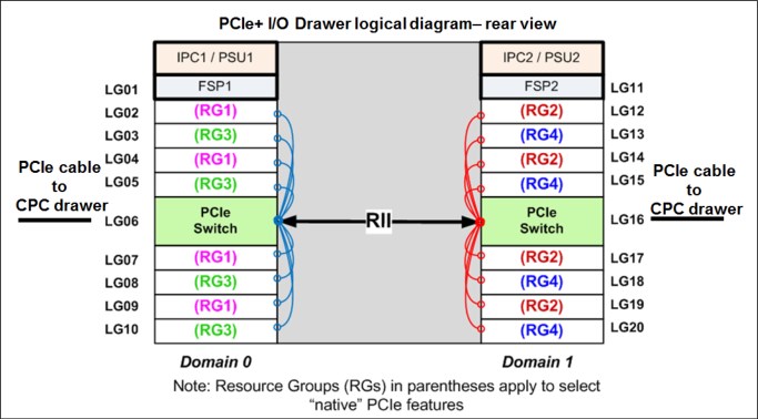
Figure 2-28 Redundant I/O Interconnect
To support Redundant I/O Interconnect (RII) between domain pair 0 and 1, the two interconnects to each pair must be driven from two different PCIe fanouts. Normally, each PCIe interconnect in a pair supports the eight features in its domain. In backup operation mode, one PCIe interconnect supports all 16 features in the domain pair.
|
Note: The PCIe Interconnect (switch) adapter must be installed in the PCIe+ I/O drawer to maintain the interconnect across I/O domains. If the adapter is removed (for a service operation), the I/O cards in that domain (up to eight) become unavailable.
|
2.7.2 Enhanced drawer availability (EDA)
With EDA, the effect of CPC drawer replacement is minimized. In a multiple CPC drawer system, a single CPC drawer can be concurrently removed and reinstalled for an upgrade or repair. Removing a CPC drawer without affecting the workload requires sufficient resources in the remaining CPC drawer.
Before removing the CPC drawer, the contents of the PUs and memory of the drawer must be relocated. PUs must be available on the remaining CPC drawers to replace the deactivated drawer. Also, sufficient redundant memory must be available if no degradation of applications is allowed. To ensure that the CPC configuration supports removal of a CPC drawer with minimal effect on the workload, consider the flexible memory option. Any CPC drawer can be replaced, including the first CPC drawer that initially contains the HSA.
Removal of a CPC drawer also removes the CPC drawer connectivity to the I/O drawers, PCIe I/O drawers, and coupling links. The effect of the removal of the CPC drawer on the system is limited by the use of redundant I/O interconnect. (For more information, see 2.7.1, “Redundant I/O interconnect” on page 70.) However, all ICA SR1.1 links that are installed in the removed CPC drawer must be configured offline.
If the enhanced drawer availability and flexible memory options are not used when a CPC drawer must be replaced, the memory in the failing drawer is also removed. This process might be necessary during an upgrade or a repair action. Until the removed CPC drawer is replaced, a power-on reset of the system with the remaining CPC drawers is supported. The CPC drawer can then be replaced and added back into the configuration concurrently.
2.7.3 CPC drawer upgrade
All fanouts that are used for I/O and coupling links are rebalanced concurrently as part of a CPC drawer addition to support better RAS characteristics.
2.8 Model configurations
When a z15 is ordered, the PUs are characterized according to their intended usage. The PUs can be ordered as any of the following items:
CP The processor is purchased and activated. PU supports running the z/OS, z/VSE, z/VM, z/TPF, and Linux on Z9 operating systems. It can also run Coupling Facility Control Code.
IFL The Integrated Facility for Linux (IFL) is a processor that is purchased and activated for use by z/VM for Linux guests and Linux on Z9 operating systems.
Unassigned IFL A processor that is purchased for future use as an IFL. It is offline and cannot be used until an upgrade for the IFL is installed. It does not affect software licenses or maintenance charges.
ICF An internal coupling facility (ICF) processor that is purchased and activated for use by the Coupling Facility Control Code.
zIIP An “Off Load Processor” for workload that supports applications such as Db2 and z/OS Container Extensions. It can also be used for “System Recovery Boost” on page 68
Additional SAP An optional processor that is purchased and activated for use as SAP (System Assist Processor).
A minimum of one PU that is characterized as a CP, IFL, or ICF is required per system. The maximum number of characterizable PUs is 190. The maximum number of zIIPs is up to twice the number of PUs that are characterized as CPs.
The following components are present in the z15 server, but they are not part of the PUs that clients purchase and require no characterization:
•SAP to be used by the channel subsystem. The number of predefined SAPs depends on the z15 model.
•One IFP, which is used in the support of designated features and functions, such as RoCE (all features), Coupling Express LR, Internal Shared Memory (ISM) SMC-D, and other management functions.
•Two spare PUs, which can transparently assume any characterization during a permanent failure of another PU.
The z15 uses features to define the number of PUs that are available for client use in each configuration. The models are listed in Table 2-10.
Table 2-10 z15 Processor Configurations
|
Feature
|
CPC
Drawers
|
PUs per
drawer
|
Active PUs
|
zIIP
|
IFP
|
Opt
SAPs
|
Base
SAPs
|
Spares
|
|||
|
CPs
|
IFLs
|
ICFs
|
uIFLs
|
||||||||
|
Max34
|
1
|
41
|
0-34
|
0-34
|
0-34
|
0-33
|
0-22
|
1
|
0-8
|
4
|
2
|
|
Max71
|
2
|
41
|
0-71
|
0-71
|
0-71
|
0-70
|
0-46
|
1
|
0-8
|
8
|
2
|
|
Max108
|
3
|
41
|
0-108
|
0-108
|
0-108
|
0-107
|
0-70
|
1
|
0-8
|
12
|
2
|
|
Max145
|
4
|
41
|
0-145
|
0-145
|
0-145
|
0-144
|
0-96
|
1
|
0-8
|
16
|
2
|
|
Max190
|
5
|
43
|
0-190
|
0-190
|
0-190
|
0-189
|
0-126
|
1
|
0-8
|
22
|
2
|
•Not all PUs available on a model are required to be characterized with a feature code. Only the PUs purchased by a customer are identified with a feature code.
•zIIP maximum quantity for new build systems follows the 2:1 ratio. It might be greater if present during MES upgrades.
•All PU conversions can be performed concurrently.
A capacity marker identifies the number of CPs that were purchased. This number of purchased CPs is higher than or equal to the number of CPs that is actively used. The capacity marker marks the availability of purchased but unused capacity that is intended to be used as CPs in the future. This status often is present for software-charging reasons.
Unused CPs are not a factor when establishing the millions of service units (MSU) value that is used for charging monthly license charge (MLC) software, or when charged on a per-processor basis.
2.8.1 Upgrades
Concurrent upgrades of CPs, IFLs, ICFs, zIIPs, or SAPs are available for the z15 server. However, concurrent PU upgrades require that more PUs are installed but not activated.
Spare PUs are used to replace defective PUs. Two spare PUs always are on a z15 server. In the rare event of a PU failure, a spare PU is activated concurrently and transparently and is assigned the characteristics of the failing PU.
If an upgrade request cannot be accomplished within the configuration, a hardware upgrade is required.
The following upgrade paths for the z15 are shown in Figure 2-29:

Figure 2-29 z15 system upgrade paths
•z15 to z15 upgrades:
– T01 Max34 to Max71, Max108 are concurrent
– No upgrade to Max154 or Max190 (these features are Factory built only)
– More I/O drawers can be added based on available space in current frames or I/O expansion frames
•Any z13 to z15:
– Feature conversion of installed zAAPs to zIIPs (default) or another processor type
– For installed OnDemand Records, change temporary zAAPs to zIIPs. Stage the record
•Any z14 M0x to z15
|
Note: The z15 CPC cannot be member in an Ensemble managed by Unified Resource Manager.
|
2.8.2 Model capacity identifier
To recognize how many PUs are characterized as CPs, the Store System Information (STSI) instruction returns a Model Capacity Identifier (MCI). The MCI determines the number and speed of characterized CPs. Characterization of a PU as an IFL, ICF, or zIIP is not reflected in the output of the STSI instruction because characterization has no effect on software charging. For more information about STSI output, see “Processor identification” on page 375.
The following distinct model capacity identifier ranges are recognized (one for full capacity and three for granular capacity):
•For full-capacity engines, model capacity identifiers 701 - 7J0 are used. They express capacity settings for 1 - 190 characterized CPs.
•Three model capacity identifier ranges offer a unique level of granular capacity at the low end. They are available when no more than 34 CPs are characterized. These three subcapacity settings are applied to up to 34 CPs, which combined offer 102 more capacity settings. For more information, see “Granular capacity”.
Granular capacity
The z15 server offers 102 capacity settings at the low end of the processor. Only 34 CPs can have granular capacity. When subcapacity settings are used, other PUs beyond 34 can be characterized only as specialty engines.
The three defined ranges of subcapacity settings have model capacity identifiers numbered 401- 434, 501 - 534, and 601 - 634.
|
Consideration: All CPs have the same capacity identifier. Specialty engines (IFLs, zIIPs, and ICFs) operate at full speed.
|
List of model capacity identifiers
Regardless of the number of CPC drawers, a configuration with one characterized CP is possible, as listed in Table 2-11.
Table 2-11 Model capacity identifiers
|
Feature
|
Model capacity identifier
|
|
Max34
|
701 - 734, 601 - 634, 501 - 534, and 401 - 434
|
|
Max71
|
701 - 771, 601 - 634, 501 - 534, and 401 - 434
|
|
Max108
|
701 - 7A8, 601 - 634, 501 - 534, and 401 - 434
|
|
Max145
|
701 - 7E5, 601 - 634, 501 - 534, and 401 - 434
|
|
Max190
|
701 - 7J0, 601 - 634, 501 - 534, and 401 - 434
|
For more information about temporary capacity increases, see Chapter 8, “System upgrades” on page 331.
2.9 Power and cooling
The z15 power and cooling system is a change from previous systems because the system is packaged in an industry standard 19-inch form factor for all the internal system elements. The configuration can be 1 - 4 frames (racks). Consider the following points:
•The power subsystem is based on the following offerings:
– Power Distribution Units (PDUs) that are mounted at the rear of the system in pairs
– Bulk Power Assembly (BPA), as with previous systems
•The system uses 3-phase power:
– Low voltage 4 wire “Delta”
– High voltage 5 wire “Wye”
•No EPO (emergency power off) switch is used.
z15 has a support element task to simulate the EPO function (only used when necessary to do a System Reset Function).
•No DC input feature is available.
•The air-cooled z15 server now has a radiator unit (RU) N+2 design for the pumps and blowers.
•The water-cooled system option for the z15 server is only available with BPA-based systems.
•No Top Exit Power feature is available because the 19-inch frame is capable of top or bottom exit of power. All line cords are 4.26 meters (14 feet). Combined with the Top Exit I/O Cabling feature, more options are available when you are planning your computer room cabling.
•The new PSCN structure uses industry standard Ethernet switches (up to four) that replace the previous IBM System Control Hubs (SCHs).
2.9.1 PDU-based configurations
The IBM Z systems operate with redundant power infrastructure. The z15 is designed with a new power infrastructure that is based on intelligent (PDUs that are mounted vertically on the rear side of the 19-inch racks and Power Supply Units for the internal components. The PDU configuration supports radiator-cooled systems only.
The PDUs are controlled by using an Ethernet port and support the following input:
•3-phase 200 - 240 V AC (wired as “Delta”)
•3-phase 380 - 415 V AC (wired as “Wye”)
The power supply units convert the AC power to DC power that is used as input for the Points of Load (POLs) in the CPC drawer and the PCIe+ I/O drawers.
The power requirements depend on the number of CPC drawers (1 - 5), number of PCIe I/O drawers (0 - 12) and I/O features that are installed in the PCIe I/O drawers.
PDUs are installed and serviced from the rear of the frame. Unused power ports should never be used by any external device.
A schematic view of a maximum configured system with PDU-based power is shown in Figure 2-30.

Figure 2-30 Rear view- maximum configured system PDU power
Each PDU installed requires a customer supplied power feed. The number of power cords that are required depends on the system configuration.
|
Note: For initial installation, all power sources are required to run the system checkout diagnostics successfully.
|
PDUs are installed in pairs. A system can have 2, 4, 6, or 8 PDUs, depending on the configuration. Consider the following points:
•Paired PDUs are A1/A2, A3/A4, B1/B2, and C1/C2.
•From the rear of the system, the odd-numbered PDUs are on the left side of the rack, and the even-numbered PDUs are on the right side of the rack.
•The total loss of one PDU in a pair has no effect on the system operation.
Components that plug into the PDUs for redundancy (using two power cords) include the following features:
•CPC Drawers, PCIe+ I/O drawers, Radiators, and Support Elements
•The redundancy for each component is achieved by plugging the power cables into the paired PDUs.
For example, the top Support Element (1), has one power supply plugged into PDU A1 and the second power supply plugged into the paired PDU A2 for redundancy.
|
Note: Customer power sources should always maintain redundancy across PDU pairs; that is, one power source or distribution panel supplies power for PDU A1 and the separate power source or distribution panel supplies power for PDU A2.
As a best practice, connect the odd-numbered PDUs (A1, B1, C1, and D1) to one power source or distribution panel, and the even-numbered PDUs (A2, B2, C2, and D2) to a separate power source or distribution panel.
|
The frame count rules (number of frames) for z15 are listed in Table 2-12.
Table 2-12 Frame count rules for z15
|
Frame Count
|
I/O drawers
|
||||||||||||
|
CPC drawers
|
0
|
1
|
2
|
3
|
4
|
5
|
6
|
7
|
8
|
9
|
10
|
11
|
12
|
|
1
|
1
|
1
|
1
|
1
|
2
|
2
|
2
|
2
|
2
|
3
|
3
|
3
|
3
|
|
2
|
1
|
1
|
1
|
2
|
2
|
2
|
2
|
2
|
3
|
3
|
3
|
3
|
3
|
|
3
|
1
|
1
|
2
|
2
|
2
|
2
|
2
|
3
|
3
|
3
|
3
|
3
|
NA
|
|
4
|
2
|
2
|
2
|
2
|
2
|
3
|
3
|
3
|
3
|
3
|
4
|
4
|
4
|
|
5
|
2
|
2
|
2
|
2
|
3
|
3
|
3
|
3
|
3
|
4
|
4
|
4
|
4
|
The number of CPC drawers and I/O drawers determines the number of racks in the system and the number of PDUs in the system.
The PDU/line cord rules (number of PDU/Cord pairs) for z15 are listed in Table 2-13
Table 2-13 PDU/line cord rules (# PDU/Cord pairs) for z15
|
PDU/Linecord
|
I/O drawers
|
||||||||||||
|
CPC drawers
|
0
|
1
|
2
|
3
|
4
|
5
|
6
|
7
|
8
|
9
|
10
|
11
|
12
|
|
1
|
1
|
1
|
1
|
1
|
2
|
2
|
2
|
2
|
2
|
3
|
3
|
3
|
3
|
|
2
|
2
|
2
|
2
|
2
|
2
|
2
|
2
|
2
|
3
|
3
|
3
|
3
|
3
|
|
3
|
2
|
2
|
2
|
2
|
2
|
2
|
2
|
3
|
3
|
3
|
3
|
3
|
NA
|
|
4
|
3
|
3
|
3
|
3
|
3
|
3
|
3
|
3
|
3
|
4
|
4
|
4
|
4
|
|
5
|
3
|
3
|
3
|
3
|
3
|
3
|
3
|
3
|
3
|
4
|
4
|
4
|
4
|
2.9.2 BPA-based configurations
The Bulk Power Assembly configuration is the feature that allows customers to have truly redundant line cords with phase loss protection and IBF (Integrated Battery Facility) support for frame level UPS power backup. Characteristics to previous IBM Z servers are similar, but were redesigned to fit into the 19-inch form factor.
No PDUs are installed in this configuration; instead, 1 or 2 pairs of BPAs are installed that house the bulk power distribution to all the components, the Bulk Power Regulators (BPR), and the optional Internal Battery Feature.
With BPA-based configurations, 3-phase balanced power feature is supported. BPA-based systems support radiator-cooled systems and water-cooled systems.
The BPAs support 2- or 4-line cords with a single universal type of 3-phase 200 - 480 V AC.
The power supply units convert the regulated high-voltage DC power (supplied by BPA) to DC power that is used as input for the Points of Load (POLs) in the CPC drawer and the PCIe+ I/O drawers.
The power requirements depend on the number of CPC drawers (1 - 5), number of PCIe I/O drawers (0 - 11), and I/O features that are installed in the PCIe+ I/O drawers.
A schematic view of a maximum configured system with BPA power is shown in Figure 2-31.

Figure 2-31 Rear view- maximum configured system BPA power
Each BPA installed requires a customer supplied power feed. The number of power cords that are required depends on the system configuration. The total loss of one BPA has no effect on system operation.
|
Note: For initial installation, all power sources are required to run the system checkout diagnostics successfully.
|
BPAs are installed in pairs 2 or 4 depending on the configuration. Consider the following points:
•BPA1 and BPA2 are always installed initially in Frame A
•BPA3 and BPA4 are installed to support more components for larger configurations (CPC and I/O drawers)
•BPA1/BPA2 and BPA3/BPA4 for paired redundancy
•From the rear of the system, the odd-numbered BPAs are above the even-numbered BPAs in both frames
•The total loss of one BPA in a pair has no effect on system operation
The following components plug into the BPAs X 2 for redundancy:
•CPC Drawers, I/O Drawers, Switches, Radiators, WCUs, and Support Elements
•The redundancy for each component plugs into the paired BPAs
For example, for the top Support Element 1, one power supply plugs into BPA1 and the second power supply plugs into the paired BPA2 for redundancy.
|
Note: Customer power sources should always maintain redundancy across BPA pairs; that is, one power source or distribution panel supplies power for BPA1 and the separate power source or distribution panel supplies power for BPA2.
As a best practice, connect the odd-numbered BPAs (BPA1 and BPA3) to one power source or distribution panel, and the even-numbered PDUs (BPA2 and BPA4) to a separate power source or distribution panel.
|
2.9.3 Internal Battery Feature
The Internal Battery Feature (IBF) is an option on the z15 server. It is shown in Figure 2-31 on page 79 for air-cooled (RCA) or water-cooled (WCA) systems. The IBF provides a local uninterrupted power source.
The IBF further enhances the robustness of the power design, which increases power line disturbance immunity. It provides battery power to preserve processor data during a loss of power on all power feeds from the computer room. The IBF can hold power briefly during a brownout, or for orderly shutdown for a longer outage. For information about the hold times, which depend on the I/O configuration and amount of CPC drawers, see Chapter 11, “Environmentals” on page 451.
2.9.4 Power estimation tool
The power estimation tool for the z15 server allows you to enter your precise server configuration to obtain an estimate of power consumption. Log in to the Resource link with your user ID. Click Planning → Tools → Power Estimation Tools. Specify the quantity for the features that are installed in your system.
This tool estimates the power consumption for the specified configuration. The tool does not verify that the specified configuration can be physically built.
|
Tip: The exact power consumption for your system varies. The object of the tool is to estimate the power requirements to aid you in planning for your system installation. Actual power consumption after installation can be confirmed by using the HMC Monitors Dashboard task.
|
2.9.5 Cooling
The PU SCMs are cooled by a cold plate that is connected to the internal water-cooling loop. The SC SCMs are air-cooled. In an air-cooled system, the radiator unit dissipates the heat from the internal water loop with air. The radiator unit provides improved availability with N+ 2 pumps and blowers. The WCUs are fully redundant in an N+1 arrangement for both the A-frame and the B-frame when present.
For all z15 servers, the CPC drawer components (except for PU SCMs) and the PCIe+ I/O drawers are air cooled by redundant fans. Airflow of the system is directed from front (cool air) to the back of the system (hot air).
Radiator-cooled (air-cooled) models
The PU SCMs in the CPC drawers are cooled by water. The internal closed water loop removes heat from PU SCMs by circulating water between the radiator heat exchanger and the cold plate that is mounted on the PU SCMs. For more information, see 2.9.6, “Radiator Cooling Unit”.
Although the PU SCMs are cooled by water, the heat is exhausted into the room from the radiator heat exchanger by forced air with blowers. At the system level, z15 servers are still air-cooled systems.
Water-cooled models
z15 servers are available as water-cooled systems. With WCU technology, z15 servers can transfer most of the heat that they generate into the building’s chilled water, which effectively reduces the heat output to the computer room.
Unlike the radiator in air-cooled models, a WCU has two water loops: An internal closed water loop and an external (chilled) water loop. The external water loop connects to the client-supplied building’s chilled water. The internal water loop circulates between the WCU heat exchanger and the PU SCMs cold plates. The loop takes heat away from the PU SCMs and transfers it to the external water loop in the WCU’s heat exchanger. For more information, see 2.9.7, “Water-cooling unit” on page 84.
In addition to the PU SCMs, the internal water loop circulates through two heat exchangers that are in the path of the exhaust air in the rear of the frames. These heat exchangers remove approximately 60% - 65% of the residual heat from the I/O drawers, PCIe I/O drawers, the air-cooled logic in the CPC drawers, and the power enclosures. Almost two-thirds of the total heat that is generated can be removed from the room by the chilled water.
Air-cooled models or water-cooled models are chosen when ordering, and the corresponding equipment is factory-installed. An MES (conversion) from an air-cooled model to a water-cooled model and vice versa is not possible.
2.9.6 Radiator Cooling Unit
There are 1 - 2 Radiator Cooling Units (RCU) in the system: One in Frame A and one in Frame B in support of water cooling of the PU SCMs within the CPC drawers. The unit includes n+2 pumps and N+1 fans. Water loops to each drawer are directly delivered by way of hoses to each drawer from manifolds.
The RCU discharges heat from the internal frame water loop to the customer’s data center.
Each RCU provides cooling to PU SCMs with closed loop water within the respective frame. No connection to an external chilled water supply is required. For the z15 server, the internal circulating water is conditioned water (BTA) that is added to the radiator unit during system installation with the Fill and Drain Tool (FC 3393).
Fill and Drain Tool
The Fill and Drain Tool (FDT) is a new design and is included with new z15 servers. The new FDT (FC3393) is not compatible with previous systems. The FDT is used to provide the internal water at the installation and for maintenance, and to remove it at discontinuance.
The new design uses a pump for filling the system and FRUs, and a compressor for draining FRUs and discontinuance. The process is faster and more effective. The FDT is shown in Figure 2-32.

Figure 2-32 Fill Drain Tool (FDT)
The radiator unit contains three independent pump FRUs. The cooling capability is a redundant N+2 design, so a single working pump and blower can support the entire load. The replacement of one pump or blower can be done concurrently and does not affect performance.
Each radiator cooling unit contains up to five independent fan assemblies that can be concurrently serviced. The number of fans present depends on the number of CPC drawers installed in the frame.
The water pumps, manifold assembly, radiator assembly (which includes the heat exchanger), and fan assemblies are the main components of the z15 RCU, as shown in Figure 2-33.

Figure 2-33 Radiator Cooling Unit (RCU)
The closed water loop in the radiator unit is shown in Figure 2-34. The warm water that is exiting from the PU SCMs cold plates enters pumps through a common manifold and is pumped through a heat exchanger where heat is extracted by the air flowing across the heat exchanger fins. The cooled water is then recirculated back into the PU SCMs cold plates.

Figure 2-34 Radiator cooling system
2.9.7 Water-cooling unit
z15 servers continue to provide the ability to cool systems with building-provided chilled water by using the WCU technology. The PU SCMs in the CPC drawers are cooled by internal closed loop water. The internal closed loop water exchanges heat with building-provided chilled water in the WCU heat exchanger. The source of the building’s chilled water is provided by the client.
A WCU is shown in Figure 2-35.

Figure 2-35 Water cooling unit
The water in the closed loop within the system exchanges heat with the continuous supply of building-provided chilled water. This water circulates between the PU SCMs cold plates and a heat exchanger within the WCU. Heat from the PU SCMs is transferred to the cold plates, where it is in turn transferred to the circulating system water (closed loop). The system water then dissipates its heat to the building-provided chilled water within the WCU’s heat exchanger. The PU SCMs are cooled efficiently in this manner.
z15 servers operate with two fully redundant WCUs in the A-frame and two fully redundant WCUs the B-frame (when present), each on separate loops. These water-cooling units each have their own facility feed and return water connections. If water is interrupted to one of the units, the other unit picks up the entire load, and the server continues to operate without interruption. You must provide independent redundant water loops to the water-cooling units to obtain full redundancy.
The internal circulating water is conditioned water that is added to the radiator unit during system installation with the Fill and Drain Tool (FC 3393). The FDT is included with new z15 servers. The FDT is used to provide the internal water at the installation and for maintenance, and to remove it at discontinuance.
Indoor Heat Exchanger (IDX)
In z15 servers, all water-cooled models have up to four IDX Indoor Heat Exchanger units that are installed on the rear of each frame that is present, as shown in Figure 2-36 on page 85. These units remove heat from the internal system water loop and internal air exits the server into the hot air exhaust aisle.

Figure 2-36 IDX Indoor Heat Exchanger
Consider the following points:
•IDX is an air-to-water heat exchange inside the frame
•Used to remove heat from the frame air stream and reject it to system water
•System water rejects heat to building chilled water
•Water turbulators are used to improve HX efficiency
In addition to the PU SCMs cold plates, the internal water loop circulates through heat exchangers that are mounted on each frame in the configuration. These exchangers are in the path of the exhaust air in the rear of the frames.
Depending on the configuration, these heat exchangers remove up to 93% of the residual heat from the I/O drawers, PCIe I/O drawer, the air-cooled logic in the CPC drawer, and the power enclosures. The goal is for two-thirds of the total heat that is generated to be removed from the room by the chilled water.
Figure 2-37 shows an example of various frame configurations. Every frame includes a heat exchanger when the water-cooling feature is ordered.
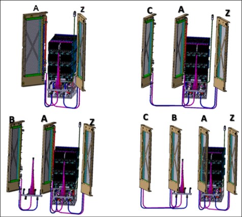
Figure 2-37 Rear door heat exchanger plumbing schematic
If one client water supply or one WCU fails, the remaining feed maintains PU SCM cooling for the frame. The WCUs and the associated drive card are concurrently replaceable. In addition, the heat exchangers can be disconnected and removed from the system concurrently.
2.10 Summary
All aspects of the z15 structure are listed in Table 2-14
Table 2-14 System structure summary
|
Description
|
Max34
|
Max71
|
Max108
|
Max145
|
Max190
|
|
Maximum number of characterized PUs
|
34
|
71
|
108
|
145
|
190
|
|
Number of CPs
|
0 - 34
|
0 - 71
|
0 - 108
|
0 - 145
|
0 - 190
|
|
Number of IFLs
|
0 - 34
|
0 - 71
|
0 - 108
|
0 - 145
|
0 - 190
|
|
Number of Unassigned IFLs
|
0 - 33
|
0 - 70
|
0 - 107
|
0 - 144
|
0 - 189
|
|
Number of ICFs
|
0 - 34
|
0 - 71
|
0 - 108
|
0 - 145
|
0 - 190
|
|
Number of zIIPs
|
0 - 22
|
0 - 46
|
0 - 70
|
0 - 96
|
0 - 126
|
|
Standard SAPs
|
4
|
8
|
12
|
16
|
22
|
|
Additional SAPs
|
0 - 8
|
0 - 8
|
0 - 8
|
0 - 8
|
0 - 8
|
|
Number of IFP
|
1
|
1
|
1
|
1
|
1
|
|
Standard spare PUs
|
2
|
2
|
2
|
2
|
2
|
|
Enabled Memory sizes GB
|
512 - 7936
|
512 - 16128
|
512 - 24320
|
512 - 32512
|
512 - 40704
|
|
Flexible memory sizes GB
|
N/A
|
512 - 7936
|
512 - 16128
|
512 - 24320
|
512 - 32512
|
|
L1 cache per PU (I/D)
|
128/128 KB
|
128/128 KB
|
128/128 KB
|
128/128 KB
|
128/128 KB
|
|
L2 cache per PU
|
48/48 MB (I/D)
|
48/48 MB (I/D)
|
48/48 MB (I/D)
|
48/48 MB (I/D)
|
48/48 MB (I/D)
|
|
L3 shared cache per PU chip
|
256 MB
|
256 MB
|
256 MB
|
256 MB
|
256 MB
|
|
L4 shared cache per drawer
|
960 MB
|
960 MB
|
960 MB
|
960 MB
|
960 MB
|
|
Cycle time (ns)
|
0.192
|
0.192
|
0.192
|
0.192
|
0.192
|
|
Clock frequency
|
5.2 GHz
|
5.2 GHz
|
5.2 GHz
|
5.2 GHz
|
5.2 GHz
|
|
Maximum number of PCIe fanouts
|
12
|
24
|
36
|
48
|
60
|
|
PCIe Bandwidth
|
16 GBps
|
16 GBps
|
16 GBps
|
16 GBps
|
16 GBps
|
|
Number of support elements
|
2
|
2
|
2
|
2
|
2
|
|
External AC power
|
3-phase
|
3-phase
|
3-phase
|
3-phase
|
3-phase
|
|
Internal Battery Feature BPA only
|
Optional
|
Optional
|
Optional
|
Optional
|
Optional
|
1 For more information, see Chapter 2, Environmental specifications in IBM Z 8561Installation Manual for Physical Planning, GC28-7002.
2 KMM - Keyboard, Mouse, Monitor
3 MPO - Multi-fiber Push On connector
4 Oscillator card (OSC) is combined (single FRU P/N) with the Flexible Support Processor (FSP); installed in pairs for each CPC Drawer
5 PPM - Parts Per Million
6 POL - Point of Load, VRM - Voltage Regulator Module.
7 Voltage Regulator Module stick converts the DC bulk power that is delivered by the PSUs (12V) into localized low voltage that is used by the installed components (for example, PU SCMs, SC SCM, memory DIMMs, and other circuitry).
8 The air density sensor measures air pressure and is used to control blower speed.
9 The KVM hypervisor is part of supported Linux on Z distributions.
..................Content has been hidden....................
You can't read the all page of ebook, please click here login for view all page.