


Hosts
This chapter describes the host configuration procedures that are required to attach supported hosts to the IBM Spectrum Virtualize system. It also introduces new concepts about Host Clusters, and N-Port Virtualization ID (NPIV) support from a host’s perspective.
This chapter includes the following topics:
8.1 Host attachment overview
The IBM Storwize V7000 system supports a wide range of host types (both IBM and non-IBM). This feature makes it possible to consolidate storage in an open systems environment into a common pool of storage. Then, you can use and manage the storage pool more efficiently as a single entity from a central point on the storage area network (SAN).
The ability to consolidate storage for attached open systems hosts provides the following benefits:
•Easier storage management
•Increased utilization rate of the installed storage capacity
•Advanced Copy Services functions offered across storage systems from separate vendors
•Only one multipath driver is required for attached hosts
Hosts can be connected to Storwize V7000 system using any of the following protocols:
•Fibre Channel (FC)
•Fibre Channel over Ethernet (FCoE)
•Internet Small Computer System Interface (iSCSI)
Hosts that connect to the Storwize V7000 system by using the fabric switches that use FC or FCoE protocol must be zoned appropriately, as indicated in 3.6, “SAN configuration planning” on page 52.
Hosts that connect to the Storwize V7000 system with iSCSI protocol must be configured appropriately, as indicated in Chapter 3, “Planning” on page 45.
|
Note: Certain host operating systems can be directly connected to the Storwize V7000 system without the need for FC fabric switches. For more information, go to the IBM System Storage Interoperation Center (SSIC):
|
For load balancing and access redundancy on the host side, the use of a host multipathing driver is required. A host multipathing I/O driver is required in the following situations:
•Protection from fabric link failures, including port failures on the IBM Spectrum Virtualize system nodes
•Protection from a host HBA failure (if two HBAs are in use)
•Protection from fabric failures if the host is connected through two HBAs to two separate fabrics
•Provide load balancing across the host HBAs
To learn about various host operating systems and versions that are supported by IBM Storwize V7000, go to the IBM System Storage Interoperation Center (SSIC):
To learn about how to attach various supported host operating systems to IBM Storwize V7000, see:
If your host operating system is not in SSIC, you can ask an IBM representative to submit a special request for support by using the Storage Customer Opportunity REquest (SCORE) tool for evaluation:
8.2 Host clusters
IBM Storwize V7000 software supports host clusters starting with V7.7.1 and later. The host cluster allows a user to create a group of hosts to form a cluster. A cluster is treated as one single entity, thus allowing multiple hosts to have access to the same volumes.
Volumes that are mapped to a host cluster will be assigned to all members of the host cluster with the same SCSI ID.
A typical user case is to define a host cluster that contains all of the WWPNs belonging to the hosts participating in a host operating system-based cluster, such as IBM PowerHA®, Microsoft Cluster Server (MSCS), and so on.
The following new commands have been added to deal with host clusters:
•lshostcluster
•lshostclustermember
•lshostclustervolumemap
•mkhost (modified to put host in a host cluster on creation)
•rmhostclustermember
•rmhostcluster
•rmvolumehostclustermap
|
Note: Host clusters enable you to create individual hosts and add them to a host cluster. Care must be taken to make sure that no loss of access occurs when changing to host clusters.
|
8.3 N-Port Virtualization ID support
The usage model for the Storwize V7000 is based on a two-way active/active node model. This is a pair of distinct control modules that share active/active access for any specific volume. These nodes each have their own Fibre Channel worldwide node name (WWNN). Therefore, ports that are presented from each node have a set of worldwide port names (WWPNs) that are presented to the fabric.
Traditionally, if one node fails or is removed for some reason, the paths that are presented for volumes from that node would go offline. In this case, it is up to the native O/S multipathing software to fail over from using both sets of WWPN to just those that remain online. While this process is exactly what multipathing software is designed to do, occasionally it can be problematic, particularly if paths are not seen as coming back online for some reason.
Starting with Storwize V7000 V7.7, the system can be enabled into N_Port ID Virtualization (NPIV) mode. When NPIV mode is enabled on the Storwize V7000 system, ports do not come online until they are ready to service I/O, which improves host behavior around node unpends. In addition, path failures due to an offline node are masked from hosts and their multipathing driver will not need to do any path recovery.
When NPIV is enabled on Storwize V7000 nodes, each physical WWPN reports up to three virtual WWPNs, as shown in Table 8-1.
Table 8-1 IBM Spectrum Virtualize NPIV Ports
|
NPIV port
|
Port description
|
|
Primary NPIV Port
|
This is the WWPN that communicates with backend storage, and might be used for node-to-node traffic. (Local or remote).
|
|
Primary Host Attach Port
|
This is the WWPN that communicates with hosts. It is a target port only,. This is the primary port, so it is based on this local node’s WWNN.
|
|
Failover Host Attach Port
|
This is a standby WWPN that communicates with hosts, and is only brought online if the partner node within the I/O Group goes offline. This is the same as the Primary Host Attach WWPN on the partner node.
|
Figure 8-1 depicts the WWPNs associated with a Storwize V7000 port when NPIV is enabled.
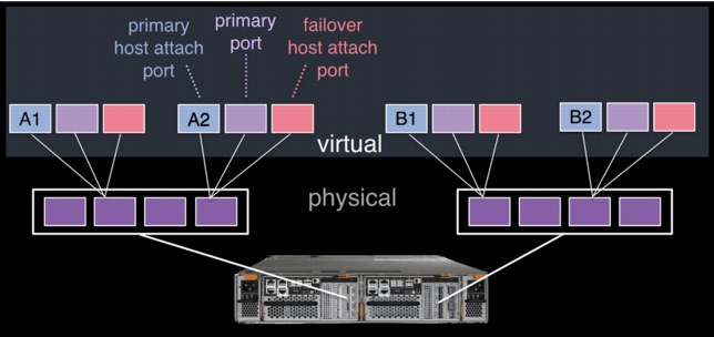
Figure 8-1 Allocation of NPIV virtual WWPN ports per physical port
The failover host attach port is not currently active. Figure 8-2 shows what happens when the partner node fails. After the node failure, the failover host attach ports on the remaining node become active and take on the WWPN of the failed node’s primary host attach port.
|
Note: Figure 8-2 shows only two ports per node in detail, but the same applies for all physical ports.
|

Figure 8-2 Allocation of NPIV virtual WWPN ports per physical port after a node failure
With V7.7 onwards, this process happens automatically when NPIV has been enabled at a system level in Storwize V7000. This failover only happens between the two nodes in the same I/O Group.
A transitional mode allows migration of hosts from previous non NPIV enabled systems to enabled NPIV system, allowing for a transition period as hosts are rezoned to the primary host attach WWPNs.
The process for enabling NPIV on a new IBM Storwize V7000 system is slightly different than on an existing system. For more information, see IBM Knowledge Center:
|
Note: NPIV is only supported for Fibre Channel protocol. It is not supported for FCoE or iSCSI protocols.
|
8.3.1 NPIV prerequisites
Consider the following key points for NPIV enablement:
•The IBM Storwize V7000 system must be running V7.7 or later.
•A V7.7 or later system with NPIV enabled as backend storage for a system that is earlier than V7.7 is not supported.
•Both nodes in an I/O group should have identical hardware to allow failover to work as expected.
•The Fibre Channel switches, that the Storwize V7000 ports are attached to, must support NPIV and have this feature enabled.
8.3.2 Enabling NPIV on a new system
New Storwize V7000 systems that are shipped with V7.7 or later should have NPIV enabled by default. If your new Storwize V7000 does not have NPIV enabled, it can be enabled by running the following steps:
Example 8-1 Listing the I/O groups in a system
IBM_Storwize:ITSO_V7000G2_B:superuser>lsiogrp
id name node_count vdisk_count host_count site_id site_name
0 io_grp0 2 2 1
1 io_grp1 0 0 1
2 io_grp2 0 0 1
3 io_grp3 0 0 1
4 recovery_io_grp 0 0 0
2. Run the lsiogrp <id> | grep fctargetportmode command for the specific I/O group ID to display the fctargetportmode setting. If this is enabled, as shown in Example 8-2, NPIV host target port mode is enabled.
Example 8-2 Checking NPIV mode with the fctargetportmode field
IBM_Storwize:ITSO_V7000G2_B:superuser>lsiogrp 0 | grep fctargetportmode
fctargetportmode enabled
IBM_Storwize:ITSO_V7000G2_B:superuser>
3. The virtual WWPNs can be listed using the lstargetportfc command, as shown in Example 8-3. Look for the host_io_permitted and virtualized columns to be yes, meaning the WWPN in those lines is a primary host attach port and should be used when zoning the hosts to the Storwize V7000.
Example 8-3 Listing the virtual WWPNs
IBM_Storwize:ITSO_V7000G2_B:superuser>lstargetportfc
id WWPN WWNN port_id owning_node_id current_node_id nportid host_io_permitted virtualized
1 500507680B2121A8 500507680B0021A8 1 1 1 011213 no no
2 500507680B2521A8 500507680B0021A8 1 1 1 011214 yes yes
3 500507680B2221A8 500507680B0021A8 2 1 1 021200 no no
4 500507680B2621A8 500507680B0021A8 2 1 1 021201 yes yes
5 500507680B2321A8 500507680B0021A8 3 1 000000 no no
6 500507680B2721A8 500507680B0021A8 3 1 000000 yes yes
7 500507680B2421A8 500507680B0021A8 4 1 1 010900 no no
8 500507680B2821A8 500507680B0021A8 4 1 1 010901 yes yes
33 500507680B2121A9 500507680B0021A9 1 2 2 011613 no no
34 500507680B2521A9 500507680B0021A9 1 2 2 011614 yes yes
35 500507680B2221A9 500507680B0021A9 2 2 2 021600 no no
36 500507680B2621A9 500507680B0021A9 2 2 2 021601 yes yes
37 500507680B2321A9 500507680B0021A9 3 2 000000 no no
38 500507680B2721A9 500507680B0021A9 3 2 000000 yes yes
39 500507680B2421A9 500507680B0021A9 4 2 2 010800 no no
40 500507680B2821A9 500507680B0021A9 4 2 2 010801 yes yes
IBM_Storwize:ITSO_V7000G2_B:superuser>
Example 8-4 NPIV enablement verification
IBM_Storwize:ITSO:superuser>lsiogrp 0
id 0
name io_grp0
node_count 2
vdisk_count 2
host_count 2
flash_copy_total_memory 20.0MB
flash_copy_free_memory 20.0MB
remote_copy_total_memory 20.0MB
remote_copy_free_memory 20.0MB
mirroring_total_memory 20.0MB
mirroring_free_memory 20.0MB
raid_total_memory 40.0MB
raid_free_memory 38.8MB
maintenance no
compression_active yes
accessible_vdisk_count 2
compression_supported yes
max_enclosures 10
encryption_supported no
flash_copy_maximum_memory 552.0MB
site_id
site_name
fctargetportmode enabled
compression_total_memory 2047.9MB
You can now configure your zones for hosts by using the primary host attach ports (virtual WWPNs) of the Storwize V7000 ports, as shown in bold in the output of Example 8-3 on page 322.
8.3.3 Enabling NPIV on an existing system
When IBM Spectrum Virtualize systems that are running code earlier than V7.7.1 are upgraded to V7.7.1 or later, by default the NPIV feature is not turned on because it might require changes to host-side zoning.
Enabling NPIV on an existing system requires that you complete the following steps after you meet the prerequisites:
1. Audit your SAN fabric layout and zoning rules because NPIV has stricter requirements. Ensure that equivalent ports are on the same fabric and in the same zone.
2. Check the path count between your hosts and the IBM Spectrum Virtualize system to ensure that the number of paths is half of the usual supported maximum.
For more information, see IBM Knowledge Center:
3. Run the lstargetportfc command to discover the primary host attach WWPNs (virtual WWPNs), as shown in bold in Example 8-5.
Example 8-5 Using the lstargetportfc command to get primary host WWPNs (virtual WWPNs)
IBM_Storwize:ITSO_V7000G2_B:superuser>lstargetportfc
id WWPN WWNN port_id owning_node_id current_node_id nportid host_io_permitted virtualized
1 500507680B2121A8 500507680B0021A8 1 1 1 011213 yes no
2 500507680B2521A8 500507680B0021A8 1 1 000000 no yes
3 500507680B2221A8 500507680B0021A8 2 1 1 021200 yes no
4 500507680B2621A8 500507680B0021A8 2 1 000000 no yes
5 500507680B2321A8 500507680B0021A8 3 1 000000 yes no
6 500507680B2721A8 500507680B0021A8 3 1 000000 no yes
7 500507680B2421A8 500507680B0021A8 4 1 1 010900 yes no
8 500507680B2821A8 500507680B0021A8 4 1 000000 no yes
33 500507680B2121A9 500507680B0021A9 1 2 2 011613 yes no
34 500507680B2521A9 500507680B0021A9 1 2 000000 no yes
35 500507680B2221A9 500507680B0021A9 2 2 2 021600 yes no
36 500507680B2621A9 500507680B0021A9 2 2 000000 no yes
37 500507680B2321A9 500507680B0021A9 3 2 000000 yes no
38 500507680B2721A9 500507680B0021A9 3 2 000000 no yes
39 500507680B2421A9 500507680B0021A9 4 2 2 010800 yes no
40 500507680B2821A9 500507680B0021A9 4 2 000000 no yes
4. Enable transitional mode for NPIV on the Storwize V7000 system (Example 8-6).
Example 8-6 NPIV in transitional mode
IBM_Storwize:ITSO_V7000G2_B:superuser>chiogrp -fctargetportmode transitional 0
IBM_Storwize:ITSO_V7000G2_B:superuser>lsiogrp 0 |grep fctargetportmode
fctargetportmode transitional
5. Ensure that the primary host attach WWPNs (virtual WWPNs) now allow host traffic, as shown in bold in Example 8-7.
Example 8-7 Host attach WWPNs (virtual WWPNs) permitting host traffic
IBM_Storwize:ITSO_V7000G2_B:superuser>lstargetportfc
id WWPN WWNN port_id owning_node_id current_node_id nportid host_io_permitted virtualized
1 500507680B2121A8 500507680B0021A8 1 1 1 011213 yes no
2 500507680B2521A8 500507680B0021A8 1 1 1 011214 yes yes
3 500507680B2221A8 500507680B0021A8 2 1 1 021200 yes no
4 500507680B2621A8 500507680B0021A8 2 1 1 021201 yes yes
5 500507680B2321A8 500507680B0021A8 3 1 000000 yes no
6 500507680B2721A8 500507680B0021A8 3 1 000000 yes yes
7 500507680B2421A8 500507680B0021A8 4 1 1 010900 yes no
8 500507680B2821A8 500507680B0021A8 4 1 1 010901 yes yes
33 500507680B2121A9 500507680B0021A9 1 2 2 011613 yes no
34 500507680B2521A9 500507680B0021A9 1 2 2 011614 yes yes
35 500507680B2221A9 500507680B0021A9 2 2 2 021600 yes no
36 500507680B2621A9 500507680B0021A9 2 2 2 021601 yes yes
37 500507680B2321A9 500507680B0021A9 3 2 000000 yes no
38 500507680B2721A9 500507680B0021A9 3 2 000000 yes yes
39 500507680B2421A9 500507680B0021A9 4 2 2 010800 yes no
40 500507680B2821A9 500507680B0021A9 4 2 2 010801 yes yes
6. Add the primary host attach ports (virtual WWPNs) to your existing host zones but do not remove the current Storwize V7000 WWPNs already in the zones. Example 8-8 shows an existing host zone to the Primary Port WWPNs of the Storwize V7000 nodes.
Example 8-8 Legacy host zone
zone: w2k880_v7G271
10:00:00:05:1e:0f:81:cc
50:05:07:68:0b:21:21:a9
50:05:07:68:0b:21:21:a8
Example 8-9 shows that we have added the primary host attach ports (virtual WWPNs) to our example host zone to allow us to change the host without disrupting its availability.
Example 8-9 Transitional host zone
zone: w2k880_v7G271
10:00:00:05:1e:0f:81:cc
50:05:07:68:0b:21:21:a9
50:05:07:68:0b:21:21:a8
50:05:07:68:0b:25:21:a8
50:05:07:68:0b:25:21:a9
7. With the transitional zoning active in your fabrics, ensure that the host is using the new NPIV ports for host I/O. Example 8-10 shows the before and after pathing for our host. Notice that the select count now increases on the new paths and has stopped on the old paths.
Example 8-10 Host device pathing, before and after
C:Program FilesIBMSDDDSM>datapath query device
Total Devices : 1
DEV#: 0 DEVICE NAME: Disk3 Part0 TYPE: 2145 POLICY: OPTIMIZED
SERIAL: 60050764008680083800000000000000 LUN SIZE: 20.0GB
============================================================================
Path# Adapter/Hard Disk State Mode Select Errors
0 * Scsi Port2 Bus0/Disk1 Part0 OPEN NORMAL 3991778 0
1 * Scsi Port2 Bus0/Disk1 Part0 OPEN NORMAL 416214 0
2 * Scsi Port3 Bus0/Disk1 Part0 OPEN NORMAL 22255 0
3 * Scsi Port3 Bus0/Disk1 Part0 OPEN NORMAL 372785 0
C:Program FilesIBMSDDDSM>datapath query device
Total Devices : 1
DEV#: 0 DEVICE NAME: Disk3 Part0 TYPE: 2145 POLICY: OPTIMIZED
SERIAL: 60050764008680083800000000000000 LUN SIZE: 20.0GB
============================================================================
Path# Adapter/Hard Disk State Mode Select Errors
0 * Scsi Port2 Bus0/Disk1 Part0 OPEN NORMAL 3991778 2
1 * Scsi Port2 Bus0/Disk1 Part0 OPEN NORMAL 416214 1
2 * Scsi Port3 Bus0/Disk1 Part0 OPEN NORMAL 22255 0
3 * Scsi Port3 Bus0/Disk1 Part0 OPEN NORMAL 372785 2
4 * Scsi Port2 Bus0/Disk1 Part0 OPEN NORMAL 22219 0
5 Scsi Port2 Bus0/Disk1 Part0 OPEN NORMAL 95109 0
6 * Scsi Port3 Bus0/Disk1 Part0 OPEN NORMAL 2 0
7 Scsi Port3 Bus0/Disk1 Part0 OPEN NORMAL 91838 0
|
Remember:
The following information can be useful:
•You can verify that you are logged in to the NPIV ports by entering the lsfabric -host host_id_or_name command. If I/O activity is occurring, each host has at least one line in the command output that corresponds to a host port and shows active in the activity field:
– Hosts where no I/O has occurred in the past 5 minutes show inactive for any login.
– Hosts that do not adhere to preferred paths might still be processing I/O to primary ports.
•Depending on the host operating system, rescanning of for storage might be required on some hosts to recognize additional paths now provided using primary host attach ports (virtual WWPNs).
|
8. After all hosts have been rezoned and the pathing validated, change the system NPIV to enabled mode by entering the command shown in Example 8-11.
Example 8-11 Enabling the NPIV
IBM_2145:ITSO:superuser>chiogrp -fctargetportmode enabled 0
Now NPIV has been enabled on the Storwize V7000 system, and you have confirmed the hosts are using the virtualized WWPNs for I/O. To complete the NPIV implementation, the host zones can be amended to remove the old primary attach port WWPNs. Example 8-12 shows our final zone with the host HBA and the Storwize V7000 virtual WWPNs.
Example 8-12 Final host zone
zone: w2k880_v7G271
10:00:00:05:1e:0f:81:cc
50:05:07:68:0b:25:21:a8
50:05:07:68:0b:25:21:a9
8.4 Hosts operations using the GUI
This section describes performing the following host operations by using the IBM Spectrum Virtualize GUI:
•Creating hosts
•Advanced host administration
•Adding and deleting host ports
•Host mappings overview
8.4.1 Creating hosts
This section describes how to create Fibre Channel and iSCSI hosts by using the Storwize V7000 GUI. It is assumed that hosts are prepared for attachment, as described in IBM Knowledge Center, and that the host WWPNs or their iSCSI initiator names are known:
To create a host, complete these steps:

Figure 8-3 Open the host window
2. To create a host, click Add Host. If you want to create a Fibre Channel host, continue with “Creating Fibre Channel hosts” on page 328. To create an iSCSI host, go to “Creating iSCSI hosts” on page 330.
Creating Fibre Channel hosts
To create Fibre Channel hosts, complete the following steps:

Figure 8-4 Fibre Channel host configuration
2. Enter a host name and click the Host Port menu to get a list of all discovered WWPNs (Figure 8-5).

Figure 8-5 Available WWPNs
3. Select one or more WWPNs for your host. The Storwize V7000 should have the host port WWPNs available if the host is prepared as described in IBM Knowledge Center for host attachment. If they do not appear in the list, scan for new disks as required on the respective operating system and click the Rescan icon in the WWPN box. If they still do not appear, check the SAN zoning and repeat the scanning.
|
Creating offline hosts: If you want to create hosts that are offline, or not connected at the moment, it is also possible to enter the WWPNs manually. Type them into the Host Ports field to add them to the list.
|
4. If you want to add more ports to your Host, click the Plus sign (+) to add all ports that belong to the specific host.
5. If you are creating a Hewlett-Packard UNIX (HP-UX) or Target Port Group Support (TPGS) host, select the Host type (Figure 8-6). Select your host type. If your specific host type is not listed, select generic.

Figure 8-6 Host type selection
6. Click Add to create the host object.
7. Click Close to return to the host window. Repeat these steps for all of your Fibre Channel hosts. Figure 8-7 shows the All Hosts window after creating a second host.

Figure 8-7 Hosts view after creating a host
After you complete the adding of Fibre Channel hosts, go to Chapter 7, “Volumes” on page 239 to create volumes and map them to the created hosts.
Creating iSCSI hosts
When creating an iSCSI attached host, consider the following points:
•iSCSI IP addresses can fail over to the partner node in the I/O Group if a node fails. This design reduces the need for multipathing support in the iSCSI host.
•The IQN of the host is added to a Storwize V7000 host object in the same way that you add FC WWPNs.
•Host objects can have both WWPNs and IQNs.
•Standard iSCSI host connection procedures can be used to discover and configure the Storwize V7000 as an iSCSI target.
•The Storwize V7000 supports the Challenge Handshake Authentication Protocol (CHAP) authentication methods for iSCSI.
•Note that iqn.1986-03.com.ibm:2076.<cluster_name>.<node_name> is the iSCSI qualified name (IQN) for a Storwize V7000 node. Because the IQN contains the clustered system name and the node name, it is important not to change these names after iSCSI is deployed.
•Each node can be given an iSCSI alias, as an alternative to the IQN.
To create iSCSI hosts, complete the following steps:

Figure 8-8 Add an iSCSI host
2. Enter a host name and the iSCSI initiator name into the iSCSI host IQN box. Click the plus sign (+) if you want to add more initiator names to one host.
3. If you are connecting an HP-UX or TPGS host, click the Host type menu and then select the correct host type. For our ESX host, we selected VVOL. However, generic is good if you are not using VVOLs.
4. Click Add and then click Close to complete the host object definition.
5. Repeat these steps for every iSCSI host that you want to create. Figure 8-9 shows the All Hosts window after creating three Fibre Channel hosts and one iSCSI host.

Figure 8-9 Defined Hosts list
Although the iSCSI host is now configured, to provide connectivity, the iSCSI Ethernet ports must also be configured.
Complete the following steps to enable iSCSI connectivity:

Figure 8-10 Network: iSCSI settings
2. On the iSCSI Configuration window we can modify the system name, node names and provide optional iSCSI Alias for each node if we want (Figure 8-11).

Figure 8-11 iSCSI Configuration window
3. The window displays an Apply Changes prompt to apply any changes you have made before continuing,
4. Lower on the configuration window, you can also configure Internet Storage Name Service (iSNS) addresses and CHAP if you need these in your environment.
|
Note: The authentication of hosts is optional. By default, it is disabled. The user can choose to enable CHAP or CHAP authentication, which involves sharing a CHAP secret between the cluster and the host. If the correct key is not provided by the host, the Storwize V7000 does not allow it to perform I/O to volumes. Also, you can assign a CHAP secret to the cluster.
|
5. Click the Ethernet Ports tab to set the iSCSI IP address for each node (Figure 8-12). Repeat this step for each port on each node that you want to use for iSCSI traffic.

Figure 8-12 Enter an iSCSI IP address
6. After entering the IP address for a port, click Modify to enable the configuration. After the changes are successfully applied, click Close.
7. You can see that iSCSI is enabled for host I/O on the required interfaces with the yes under the Host Attach column. See Figure 8-13.

Figure 8-13 Action menu to modify iSCSI hosts
8. By default, iSCSI host connection is enabled after setting the IP address. To disable any interfaces you do not want to be used for host connections, click Actions and select Modify iSCSI Hosts (Figure 8-14).

Figure 8-14 Disabling iSCSI host connections
The IBM Storwize V7000 is now configured and ready for iSCSI host use. Note the initiator IQN names of your Storwize V7000 node canisters (Figure 8-11 on page 333), because you need them when adding storage on your host. To create volumes and map them to a host, go to Chapter 7, “Volumes” on page 239.
8.4.2 Host clusters
Storwize V7000 V7.7 introduced the concept of a host cluster. A host cluster allows a user to group individual hosts to form a cluster, which is treated as one entity instead of dealing with all of the hosts individually in the cluster.
The host cluster is useful for hosts that are participating in a cluster at host operating system levels. Examples are Microsoft Clustering Server, IBM PowerHA, Red Hat Cluster Suite, and VMware ESX. By defining a host cluster, a user can map one or more volumes to the host cluster object.
As a result, the volume or set of volumes gets mapped to each individual host object that is part of the host cluster. Importantly, each of the volumes gets mapped with the same SCSI ID to each host that is part of the host cluster with single command.
Even though a host is part of a host cluster, volumes can still be assigned to an individual host in a non-shared manner. A policy can be devised that can pre-assign a standard set of SCSI IDs for volumes to be assigned to the host cluster, and another set of SCSI IDs to be used for individual assignments to hosts.
|
Note: For example, SCSI IDs 0 - 100 for individual host assignment, and SCSI IDs above 100 can be used for host cluster. By employing such a policy, wanted volumes will not be shared, and others can be. For example, the boot volume of each host can be kept private, while data and application volumes can be shared.
|
This section describes how to create a host cluster. It is assumed that individual hosts have already been created as described in the previous section.

Figure 8-15 Host Clusters

Figure 8-16 Add nodes to a host cluster
3. Enter a cluster name and select the individual nodes that you want in the cluster object, and click Next.
4. A summary is displayed allowing you to confirm that you have selected the correct hosts. Click Make Host Cluster (Figure 8-17).

Figure 8-17 Create host cluster summary
5. After the task completes, click Close to return to the Host Cluster view, where you can see the cluster that you just created (Figure 8-18).

Figure 8-18 Host Cluster view
|
Note: Our cluster shows as Degraded because we have added an offline host. This status will display as Online when all hosts in the cluster are available.
|
From the Host Clusters view, you have many options to manage and configure the host cluster. These options are accessed by selecting a cluster and clicking Actions (Figure 8-19).

Figure 8-19 Host Clusters Actions menu
From the Actions menu, we can perform these actions:
•View Hosts status within the cluster.
•Add or Remove Hosts from the cluster.
•Rename the host cluster.
•Modify Shared Volume mappings allows you to add or remove volumes mapped to all hosts in the cluster while maintaining the same SCSI ID for all hosts.
•Modify Host Type can be used to change from generic to VVOLs as an example.
•Modify I/O Groups for Hosts is used to assign or restrict volume access to specific I/O groups.
•Edit Throttle is used restrict MBps or IOPS bandwidth for the Host Cluster.
•View All Throttles displays any throttling settings and allows for changing, deleting, or refining Throttle settings.
8.4.3 Advanced host administration
This section covers host administration, including topics such as host modification, host mappings, and deleting hosts. Basic host creation using FC and iSCSI connectivity is described in 8.4.1, “Creating hosts” on page 327.
It is assumed that hosts have been created in your IBM Spectrum Virtualize GUI, and that some volumes are already mapped to them. This section describes three functions that are covered in the Hosts section of the IBM Spectrum Virtualize GUI (Figure 8-20):
•Ports by Host (8.4.4, “Adding and deleting host ports” on page 353)
•Host Mappings (8.4.5, “Host mappings overview” on page 359)

Figure 8-20 IBM Spectrum Virtualize Hosts menu
In the Hosts → Hosts view, three hosts have been created and volumes are already mapped to them in our example. If needed we can now modify these hosts with the following options.
1. Select a host and click Actions or right-click the host to see the available tasks (Figure 8-21).

Figure 8-21 Host Actions
Modifying Volume Mappings
To modify what volumes are mapped to a specific host, complete the following steps:
1. From the Actions menu, select Modify Volume Mappings (Figure 8-21). The window shown in Figure 8-22 opens. At the upper left, you can confirm that the correct host is targeted. The list shows all volumes that are currently mapped to the selected host. In our example, one volume with SCSI ID 0 is mapped to the host ESX_62.

Figure 8-22 Modify Host Volume Mapping window
2. By selecting a listed volume, you can remove that Volume map from the host. However in our case we want to add an additional volume to our host. Continue by clicking Add Volume Mapping (Figure 8-23).
. 
Figure 8-23 Volumes selection list
A new list displays that shows all volumes. You can easily identify if a volume you want to map is already mapped to another host.
3. To map a volume, select it and click Next to map it to the host. The volume will be assigned the next available SCSI ID you we leave System Assign selected. However, by selecting Self Assign, you are able to manually set a SCSI ID of choice (Figure 8-24).

Figure 8-24 Modify Host Volume Mappings: Assign SCSI ID
If you select a SCSI ID already in use for the host, you cannot proceed. In Figure 8-24, we have selected SCSI ID 0. However, in the right column we can see SCSI ID 0 is already allocated. By changing to SCSI ID 1, we are able to click Next.
4. A summary window opens showing the new mapping details (Figure 8-25). After confirming that this is what you planned, click Map Volumes and then click Close.

Figure 8-25 Confirm Modified Mappings
|
Note: The SCSI ID of the volume can be changed only before it is mapped to a host. Changing it after is not possible unless the volume is unmapped from it again.
|
Unmapping all volumes from a host
A host is able to access only those volumes on your Storwize V7000 system that are mapped to it. If we want to remove access to all volumes for one host, regardless of how many volumes are mapped to it, complete this task in these simple steps:
1. From the Hosts pane, select the host, click Actions → Unmap All Volumes to remove all access that the selected host has to its volumes (Figure 8-26).

Figure 8-26 Unmap All Volumes action
2. You are prompted to confirm the number of mappings to be removed. To confirm your action, enter the number of volumes to be removed and click Unmap (Figure 8-27). In this example, we removed two volume mappings.

Figure 8-27 Confirm the number of mappings to be removed
|
Unmapping: If you click Unmap, all access for this host to volumes that are controlled by the Storwize V7000 system is removed. Ensure that you run the required procedures on your host operating system (OS), such as unmounting the file system, taking the disk offline, or disabling the volume group, before removing the volume mappings from your host object on Storwize V7000 GUI.
|
3. The changes are applied to the system. Click Close. Figure 8-28 shows that the selected host no longer has any host mappings.

Figure 8-28 All mappings for host ESX_62 have been removed
Duplicating and importing mappings
Volumes that are assigned to one host can be quickly and simply mapped to another host object. You might do this, for example, when replacing an aging hosts hardware and want to ensure that the replacement host node has access to same set of volumes as the old host.
You can accomplish this in two ways: By duplicating the mappings on the existing host object to the new host object, or by importing the host mappings to the new host. To duplicate the mappings, complete these steps:
1. To Duplicate an existing host mapping, select the host that you want to duplicate, and click Actions → Duplicate Volume Mappings (Figure 8-29). In our example, we duplicate the volumes that are currently mapped to host ESX_62 to the new host ESX_61.

Figure 8-29 Duplicate Host Volume Mappings menu
2. The Duplicate Mappings window opens. Select a listed target host object to which you want to map all the existing source host volumes and click Duplicate (Figure 8-30).

Figure 8-30 Duplicate mappings window
|
Note: You can duplicate mappings only to a host that has no volumes mapped.
|
3. After the task completion is displayed, we can verify the new mappings on the new host object. From the Hosts menu (Figure 8-29 on page 345), right-click the target host and select Properties.
4. Click the Mapped Volumes tab and verify that the required volumes have been mapped to the new host (Figure 8-31).

Figure 8-31 Host Details, new mappings on target host
The same can be accomplished by importing existing hosts mappings to the new host:
1. In this case select the new host without any mapped volumes and click Actions → Import Volume Mappings (Figure 8-32).

Figure 8-32 Hosts Actions: Import Volume Mappings
2. The import mappings window appears. Select the appropriate source host that you want to import the volume mappings from. In Figure 8-33, we select the host ESX_62 and click Import.

Figure 8-33 import volume mappings source host selection
3. After the task completes, verify that the mappings are as expected from the Hosts menu (Figure 8-29 on page 345), right-click the target host, and select Properties. Then, click the Mapped Volumes tab and verify that the required volumes have been mapped to the new host (Figure 8-31 on page 346).
Renaming a host
To rename a host, complete the following steps:

Figure 8-34 Rename a host
2. Enter a new name and click Rename (Figure 8-35). If you click Reset, the changes are reset to the original host name.

Figure 8-35 Rename Host window
3. After the changes are applied to the system, click Close.
Removing a host
To remove a host object definition, complete the following steps:

Figure 8-36 Remove a host
2. Confirm that the window displays the correct list of hosts that you want to remove by entering the number of hosts to remove, and click Delete (Figure 8-37).

Figure 8-37 Confirm the removal of the host
3. If the host that you are removing has volumes mapped to it, force the removal by selecting the check box in the lower part of the window. By selecting this check box, the host is removed and it no longer has access to any volumes on this system.
4. After the task is completed, click Close.
Host properties
To view a host object’s properties, complete the following steps:
1. From the IBM Spectrum Virtualize GUI Hosts pane, select a host and right-click it or click Actions → Properties (Figure 8-38).

Figure 8-38 Host properties
The Host Details window opens (Figure 8-39).

Figure 8-39 Host properties overview
The Host Details window shows an overview of the selected host properties. It has three tabs: Overview, Mapped Volumes, and Port Definitions. The Overview tab is shown in Figure 8-39 on page 350.

Figure 8-40 Host Properties: Show details

Figure 8-41 Edit host properties
In the window shown in Figure 8-41, you can modify the following properties:
– Host Name. Change the host name.
– Host Type. If you are going to attach HP/UX, OpenVMS, or TPGS hosts, change this setting.
– I/O Group. Host has access to volumes mapped from selected I/O Groups.
– iSCSI CHAP Secret. Enter or change the iSCSI CHAP secret if this host is using iSCSI.
4. When finished making changes, click Save to apply them. The editing window closes.
The Mapped Volumes tab shows a summary of which volumes are currently mapped with which SCSI ID and UID to this host (Figure 8-42). The Show Details slider does not show any additional information for this list.

Figure 8-42 Mapped volumes tab
The Port Definitions tab shows the configured host ports of a host and provides status information about them (Figure 8-43).

Figure 8-43 Port definitions
This window offers the option to Add or Delete Port on the host, as described in 8.4.4, “Adding and deleting host ports” on page 353.
5. Click Close to close the Host Details window.
8.4.4 Adding and deleting host ports
To configure host ports, complete the following steps:

Figure 8-44 Ports by Host
2. A list of all the hosts is displayed. The function icons indicate whether the host is Fibre Channel, iSCSI, or SAS attached. The port details of the selected host are shown to the right. You can add a new host object by clicking Add Host. If you click Actions (Figure 8-45), the tasks that are described in “Modifying Volume Mappings” on page 340 can be selected.

Figure 8-45 Ports by Host actions
Adding a Fibre Channel or iSCSI host port
To add a host port, complete the following steps:
1. Select the host.
a. Select Fibre Channel Port (see “Adding a Fibre Channel port” on page 355).
b. Select iSCSI Port (see “Adding an iSCSI host port” on page 356).

Figure 8-46 Add host ports
Adding a Fibre Channel port
To add a Fibre Channel port, complete the following steps:

Figure 8-47 Add Fibre Channel Ports window
2. Click the drop-down menu to display a list of all discovered Fibre Channel WWPNs. If the WWPN of your host is not available in the menu, enter it manually or check the SAN zoning to ensure that connectivity has been configured, then rescan storage from the host.

Figure 8-48 Add a port to list
This step can be repeated to add more ports to the host.
4. To add an offline port (if the WWPN of your host is not available in the drop-down menu), manually enter the WWPN of the port into the Fibre Channel Ports field and click Add Port to List.
The port is unverified (Figure 8-49) because it is not logged on to the SVC. The first time that it logs on, its state is automatically changed to online, and the mapping is applied to this port.

Figure 8-49 Unverified port
5. To remove a port from the adding list, click the red X next to the port. In this example, we delete the manually added FC port so only the detected port remains.
6. Click Add Ports to Host to apply the changes and click Close.
Adding an iSCSI host port
To add an iSCSI host port, complete the following steps:

Figure 8-50 Add iSCSI host ports

Figure 8-51 Enter the initiator name
3. Click Add Ports to Host to apply the changes to the system and click Close.
Deleting a host port
To delete a host port, complete the following steps:

Figure 8-52 Delete host port

Figure 8-53 Delete several host ports
2. Click Delete and confirm the number of host ports that you want to remove by entering that number in the Verify field (Figure 8-54).

Figure 8-54 Enter the number of host ports to delete
3. Click Delete to apply the changes and then click Close.
|
Note: Deleting FC and iSCSI ports is done the same way.
|
8.4.5 Host mappings overview

Figure 8-55 Host mappings
This window lists all hosts and volumes. This example shows that the host Win2012_FC has two mapped volumes, and their associated SCSI ID, Volume Name, and Volume Unique Identifier (UID). If you have more than one caching I/O group, you also see which volume is handled by which I/O group.
If you select one line and click Actions (Figure 8-56), the following tasks are available:
•Unmap Volumes

Figure 8-56 Host Mappings Actions menu
Unmapping a volume
This action removes the mappings for all selected entries. From the Actions menu shown in Figure 8-56, select one or more lines (while holding the Ctrl key), click Unmap Volumes. Confirm how many volumes are to be unmapped by entering that number in the Verify field (Figure 8-57), and then click Unmap.

Figure 8-57 Unmap selected volumes
Properties (Host)
Selecting an entry and clicking Properties (Host), as shown in Figure 8-56 on page 359, opens the host properties window. The contents of this window are described in “Host properties” on page 350.
Properties (Volume)
Selecting an entry and clicking Properties (Volume), as shown in Figure 8-56 on page 359, opens the volume properties view. The contents of this window are described in Chapter 7, “Volumes” on page 239.
8.5 Hosts operations using CLI
This section describes some of the host-related actions that can be taken within the Storwize V7000 system by using the command-line interface (CLI).
8.5.1 Create a host by using CLI
This section describes how to create Fibre Channel and iSCSI hosts by using the IBM Spectrum Virtualize CLI. It is assumed that hosts are prepared for attachment, as described in the Storwize V7000 host attachment section of IBM Knowledge Center:
Creating Fibre Channel hosts
To create a Fibre Channel host, complete the described steps:
Example 8-13 Rescanning the SAN
IBM_Storwize:ITSO:superuser>detectmdisk
|
Note: The detectmdisk command does not return any response.
|
If the zoning has been implemented correctly, any new WWPNs should be discovered by the Storwize V7000 system after running the detectmdisk command.
2. List the candidate WWPNs and identify the WWPNs belonging to the new host, as shown in Example 8-14.
Example 8-14 Available WWPNs
IBM_Storwize:ITSO:superuser>lshbaportcandidate
id
2101001B32BA36B4
2100001B329A36B4
Example 8-15 Host creation
IBM_Storwize:ITSO:superuser>mkhost -name RHEL_HOST -fcwwpn 2100001B329A36B4:2101001B32BA36B4
Host, id [7], successfully created
Creating iSCSI hosts
Before you create an iSCSI host in Storwize V7000, the iSCSI qualified name (IQN) address of the host needs to be known. See your host operating system-specific documentation to find the IQN of the host.
Create a host by completing these steps:
Example 8-16 Creating an iSCSI host by using the mkhost command
IBM_Storwize:ITSO:superuser>mkhost -iscsiname iqn.1994-05.com.redhat:e6dd277b58 -name iSCSI_RHEL_HOST
Host, id [8], successfully created
Example 8-17 Verifying the iSCSI host by using the lshost command
IBM_Storwize:ITSO:superuser>lshost 8
id 8
name iSCSI_RHEL_HOST
port_count 1
type generic
mask 1111111111111111111111111111111111111111111111111111111111111111
iogrp_count 4
status offline
site_id
site_name
host_cluster_id
host_cluster_name
iscsi_name iqn.1994-05.com.redhat:e6dd277b58
node_logged_in_count 0
state offline
|
Note: When the host is initially configured, the default authentication method is set to no authentication, and no CHAP secret is set. To set a CHAP secret for authenticating the iSCSI host with the Storwize V7000 system, use the chhost command with the chapsecret parameter. If you must display a CHAP secret for a defined server, use the lsiscsiauth command. The lsiscsiauth command lists the CHAP secret that is configured for authenticating an entity to the Storwize V7000 system.
Note: FC hosts and iSCSI hosts are handled in the same way operationally after they are created.
|
8.5.2 Advanced host administration by using the CLI
This section describes the following advanced host operations, which can be carried out using the CLI:
•Mapping a volume to a host
•Mapping a volume already mapped to a different host
•Unmapping a volume from a host
•Renaming a host
•Host properties
Mapping a volume to a host
To map a volume, complete the following steps:
1. To map an existing volume to a host, the mkvdiskhostmap command can be issued, as shown in Example 8-18.
Example 8-18 Mapping a volume
IBM_Storwize:ITSO:superuser>mkvdiskhostmap -host RHEL_HOST -scsi 0 RHEL_VOLUME
Virtual Disk to Host map, id [0], successfully created
2. The volume mapping can then be checked by issuing the lshostvdiskmap command against that particular host, as shown in Example 8-19.
Example 8-19 Checking the mapped volume
IBM_Storwize:ITSO:superuser>lshostvdiskmap RHEL_HOST
id name SCSI_id vdisk_id vdisk_name vdisk_UID IO_group_id IO_group_name mapping_type host_cluster_id host_cluster_name
7 RHEL_HOST 0 109 RHEL_VOLUME 600507680C81825B0000000000000154 0 io_grp0 private
Mapping a volume that is already mapped to a different host
To map a volume to another host that has already been mapped to one host, complete these steps:
Example 8-20 Mapping the same volume to a second host
IBM_Storwize:ITSO:superuser>mkvdiskhostmap -force -host iSCSI_RHEL_HOST -scsi 0 RHEL_VOLUME
Virtual Disk to Host map, id [0], successfully created
|
Note: The volume RHEL_VOLUME is mapped to both of the hosts using the same SCSI ID. Typically, that is the requirement for most host-based clustering software, such as Microsoft Clustering Service (MSCS), IBM PowerHA, VMware ESX clustering and so on.
|
2. The volume RHEL_VOLUME is mapped to two hosts (RHEL_HOST and iSCSI_RHEL_HOST), and can be seen by issuing the lsvdiskhostmap command, as shown in Example 8-21.
Example 8-21 Ensuring the same volume is mapped to multiple hosts
IBM_Storwize:ITSO:superuser>lsvdiskhostmap RHEL_VOLUME
id name SCSI_id host_id host_name vdisk_UID IO_group_id IO_group_name mapping_type host_cluster_id host_cluster_name
109 RHEL_VOLUME 0 7 RHEL_HOST 600507680C81825B0000000000000154 0 io_grp0 private
109 RHEL_VOLUME 0 8 iSCSI_RHEL_HOST 600507680C81825B0000000000000154 0 io_grp0 private
Unmapping a volume from a host
To unmap a volume from the host, the rmvdiskhostmap command is used, as shown in Example 8-22.
Example 8-22 Unmapping a volume from a host
IBM_Storwize:ITSO:superuser>rmvdiskhostmap -host iSCSI_RHEL_HOST RHEL_VOLUME
|
Important: Before unmapping a volume from a host on Storwize V7000, ensure that the host side action is completed on that volume by using the respective host operating system platform commands, such as unmounting the file system, or removing the volume or volume group. Otherwise, it could potentially result in data corruption.
|
Renaming a host
To rename an existing host definition, issue the chhost -name command, as shown in Example 8-23. In this example, the host RHEL_HOST has now been renamed to FC_RHEL_HOST.
Example 8-23 Renaming a host
IBM_Storwize:ITSO:superuser>chhost -name FC_RHEL_HOST RHEL_HOST
Removing a host
To remove a host from the Storwize V7000, the rmhost command is used, as shown in Example 8-24.
Example 8-24 Removing a host
IBM_Storwize:ITSO:superuser>rmhost iSCSI_RHEL_HOST
|
Note: Before removing a host from Storwize V7000, ensure that all of the volumes are unmapped from that host, as described in Example 8-22.
|
Host properties
To get more details about a particular host, the lshost command can be used with the hostname or host id as a parameter, as shown in Example 8-25.
Example 8-25 Host details
IBM_Storwize:ITSO:superuser>lshost FC_RHEL_HOST
id 7
name FC_RHEL_HOST
port_count 2
type generic
mask 1111111111111111111111111111111111111111111111111111111111111111
iogrp_count 4
status online
site_id
site_name
host_cluster_id
host_cluster_name
WWPN 2101001B32BA36B4
node_logged_in_count 2
state inactive
WWPN 2100001B329A36B4
node_logged_in_count 2
state inactive
8.5.3 Adding and deleting a host port by using the CLI
This section describes adding and deleting a host port to and from Storwize V7000.
Adding ports to a defined host
If an HBA is added, or if a network interface controller (NIC) is to be added to a server that is defined within the Storwize V7000, the addhostport command can be used to add the new port definitions to the host configuration.
If the host is connected through SAN with FC, and if the WWPN is zoned to the Storwize V7000 system, issue the lshbaportcandidate command to compare it with the information that is available from the server administrator, as shown in Example 8-26.
Example 8-26 Listing the new available WWPN
IBM_Storwize:ITSO:superuser>lshbaportcandidate
id
210000E08B054CAA
Use host or SAN switch utilities to verify whether the WWPN matches the information for the new WWPN. If the WWPN matches, use the addhostport command to add the port to the host, as shown in Example 8-27.
Example 8-27 Adding the newly discovered WWPN to the host definition
IBM_Storwize:ITSO:superuser>addhostport -hbawwpn 210000E08B054CAA FC_RHEL_HOST
This command adds the WWPN of 210000E08B054CAA to the host FC_RHEL_HOST.
|
Note: Multiple ports can be added at one time by using the separator or colon (:) between WWPNs, as shown in the following example:
addhostport -hbawwpn 210000E08B054CAA:210000E08B89C1CD FC_RHEL_HOST
|
If the new HBA is not connected or zoned, the lshbaportcandidate command does not display your WWPN. In this case, you can manually enter the WWPN of your HBA or HBAs and use the -force flag to create the host, as shown in Example 8-28.
Example 8-28 Adding a WWPN to the host definition using the -force option
IBM_Storwize:ITSO:superuser>addhostport -hbawwpn 210000E08B054CAA -force FC_RHEL_HOST
This command forces the addition of the WWPN that is named 210000E08B054CAA to the host called FC_RHEL_HOST.
|
Note: WWPNs are not case-sensitive within the CLI.
|
The host port count can be verified by running the lshost command again. The host FC_RHEL_HOST has an updated port count of 3, as shown in Example 8-29.
Example 8-29 Host with updated port count
IBM_Storwize:ITSO:superuser>lshost
id name port_count iogrp_count status site_id site_name host_cluster_id host_cluster_name
5 ARCHX513HT6_RHEV_H_HOST_1 2 4 online
6 ARCHX513HT7_RHEV_H_HOST_2 2 4 online
7 FC_RHEL_HOST 3 4 online
11 ZJ_ARCSUN42KD0603 1 4 online
12 ZJ_ARCSUN42KD0629 1 4 online
13 lxia_YF 1 4 online
17 ZJ_ARCX36506V8XM 2 4 online
18 ZJ_ARCX36506V8YV 2 4 online
If the host uses iSCSI as a connection method, the new iSCSI IQN ID should be used to add the port. Unlike FC-attached hosts, with iSCSI, available candidate ports cannot be checked.
After getting the other iSCSI IQN, issue the addhostport command, as shown in Example 8-30.
Example 8-30 Adding an iSCSI port to the defined host
IBM_Storwize:ITSO:superuser>addhostport -iscsiname iqn.1994-05.com.redhat:e6dd277b58 iSCSI_RHEL_HOST
Deleting ports from a defined host
If a mistake is made while adding a port, or if an HBA is removed from a server that is defined within the Storwize V7000, use the rmhostport command to remove WWPN definitions from an existing host.
Before removing the WWPN, ensure that it is the correct WWPN by issuing the lshost command, as shown in Example 8-31.
Example 8-31 Using the lshost command to check the WWPNs
IBM_Storwize:ITSO:superuser>lshost FC_RHEL_HOST
id 7
name FC_RHEL_HOST
port_count 3
type generic
mask 1111111111111111111111111111111111111111111111111111111111111111
iogrp_count 4
status degraded
site_id
site_name
host_cluster_id
host_cluster_name
WWPN 210000E08B054CAA
node_logged_in_count 0
state offline
WWPN 2101001B32BA36B4
node_logged_in_count 2
state active
WWPN 2100001B329A36B4
node_logged_in_count 2
state active
When the WWPN or iSCSI IQN that needs to be deleted is known, use the rmhostport command to delete a host port, as shown in Example 8-32.
Example 8-32 Using the rmhostport command to remove a WWPN
IBM_Storwize:ITSO:superuser>rmhostport -fcwwpn 210000E08B054CAA FC_RHEL_HOST
Use the command to remove the iSCSI IQN as shown in Example 8-33.
Example 8-33 Removing iSCSI port from the host
IBM_Storwize:ITSO:superuser>rmhostport -iscsiname iqn.1994-05.com.redhat:e6dd277b58 iSCSI_RHEL_HOST
This command removes the WWPN of 210000E08B054CAA from the FC_RHEL_HOST host and the iSCSI IQN iqn.1994-05.com.redhat:e6dd277b58 from the host iSCSI_RHEL_HOST.
|
Note: Multiple ports can be removed at one time by using the separator or colon (:) between the port names, as shown in the following example:
rmhostport -hbawwpn 210000E08B054CAA:210000E08B892BCD Angola
|
8.5.4 Host Cluster Operations
This section describes the following host cluster operations that can be performed by using the CLI:
•Creating a host cluster (mkhostcluster)
•Adding a member to the host cluster (addhostclustermember)
•Listing a host cluster (lshostcluster)
•Listing a host cluster member (lshostclustermember)
•Assigning a volume to the host cluster (mkvolumehostclustermap)
•Listing a host cluster for mapped volumes (lshostclustervolumemap)
•Unmapping a volume from the host cluster (rmvolumehostclustermap)
•Removing a host cluster member (rmhostclustermember)
•Removing the host cluster (rmhostcluster)
Creating a host cluster
To create a host cluster, the command mkhostcluster can be used, as shown in Example 8-34.
Example 8-34 Creating a host cluster by using mkhostcluster
IBM_Storwize:ITSO:superuser>mkhostcluster -name ITSO_HOST_CLUSTER
Host cluster, id [0], successfully created.
|
Note: While creating the host cluster, if you want it to inherit the volumes mapped to a particular host, then use the -seedfromhost flag option. Any volume mapping that does not need to be shared can be kept private by using -ignoreseedvolume flag option.
|
Adding a host to a host cluster
After creating a host cluster, a host or a list of hosts can be added by using the addhostclustermember command, as shown in Example 8-35.
Example 8-35 Adding a host or hosts to a host cluster
IBM_Storwize:ITSO:superuser>addhostclustermember -host ITSO_HOST_1:ITSO_HOST_2 ITSO_HOST_CLUSTER
In Example 8-35, the hosts ITSO_HOST_1 and ITSO_HOST_2 are added as part of host cluster ITSO_HOST_CLUSTER.
Listing the host cluster member
To list the host members that are part of a particular host cluster, the lshostclustermember command can be used, as shown in Example 8-36.
Example 8-36 Listing host cluster members with the lshostclustermember command
IBM_Storwize:ITSO:superuser>lshostclustermember ITSO_HOST_CLUSTER
host_id host_name status type site_id site_name
4 ITSO_HOST_1 offline generic
5 ITSO_HOST_2 offline generic
Mapping a volume to a host cluster
To map a volume to a host cluster so that it automatically gets mapped to member hosts, the mkvolumehostclustermap command can be used, as shown in Example 8-37.
Example 8-37 Mapping a volume to a host cluster
IBM_Storwize:ITSO:superuser>mkvolumehostclustermap -hostcluster ITSO_HOST_CLUSTER ITSO_VD_1
Volume to Host Cluster map, id [0], successfully created
|
Note: When a volume is mapped to a host cluster, that volume gets mapped to all of the members of the host cluster with the same SCSI_ID.
|
Listing the volumes that are mapped to a host cluster
To list the volumes that are mapped to a host cluster, the lshostclustervolumemap command can be used, as shown in Example 8-38.
Example 8-38 Listing volumes that are mapped to a host cluster by using lshostclustervolumemap
IBM_Storwize:ITSO:superuser>lshostclustervolumemap ITSO_HOST_CLUSTER
id name SCSI_id volume_id volume_name volume_UID IO_group_id IO_group_name
0 ITSO_HOST_CLUSTER 0 86 ITSO_VD_1 60050768018786C188000000000001E1 0 io_grp0
0 ITSO_HOST_CLUSTER 1 87 ITSO_VD_2 60050768018786C188000000000001E2 0 io_grp0
0 ITSO_HOST_CLUSTER 2 88 ITSO_VD_3 60050768018786C188000000000001E3 0 io_grp0
|
Note: The lshostvdiskmap command can be run against each host that is part of a host cluster to ensure that the mapping type for the shared volume is shared, and is private for the non-shared volume.
|
Removing a volume mapping from a host cluster
To remove a volume mapping to a host cluster, use the rmvolumehostclustermap command, as shown in Example 8-39.
Example 8-39 Removing a volume mapping
IBM_Storwize:ITSO:superuser>rmvolumehostclustermap -hostcluster ITSO_HOST_CLUSTER ITSO_VD_1
In Example 8-39, volume ITSO_VD_1 has been unmapped from the host cluster ITSO_HOST_CLUSTER. The current volume mapping can be checked to ensure that the volume has been unmapped, as shown in Example 8-38.
|
Note: To specify the host or hosts that acquire private mappings from the volume that is being removed from the host cluster, specify the -makeprivate flag.
|
Removing a host cluster member
To remove a host cluster member, use the rmhostclustermember command, as shown in Example 8-40.
Example 8-40 Removing a host cluster member
IBM_Storwize:ITSO:superuser>rmhostclustermember -host ITSO_HOST_2 -removemappings ITSO_HOST_CLUSTER
In Example 8-40, the host ITSO_HOST_2 has been removed as a member from the host cluster ITSO_HOST_CLUSTER, along with the associated volume mappings, due to the -removemappings flag being specified.
Removing a host cluster
To remove a host cluster, use the rmhostcluster command, as shown in Example 8-41.
Example 8-41 Removing a host cluster
IBM_Storwize:ITSO:superuser>rmhostcluster -removemappings ITSO_HOST_CLUSTER
The -removemappings flag also causes the system to remove any host mappings to volumes that are shared. The mappings are deleted before the host cluster is deleted.
|
Note: To keep the volumes mapped to the host objects even after the host cluster is deleted, specify the -keepmappings flag instead of -removemappings for the rmhostcluster command. When -keepmappings is specified, the host cluster is deleted but the volume mapping to the host becomes private instead of shared.
|
..................Content has been hidden....................
You can't read the all page of ebook, please click here login for view all page.