


Advanced Copy Services
This chapter describes the Advanced Copy Services and the storage software capabilities to support the interaction with hybrid clouds. Both functions are enabled by IBM Spectrum Virtualize software that is running inside of IBM SAN Volume Controller and Storwize family products.
This chapter includes the following topics:
11.1 IBM FlashCopy
By using the IBM FlashCopy function of the IBM Spectrum Virtualize, you can perform a point-in-time copy of one or more Volumes. This section describes the inner workings of FlashCopy and provides details about its configuration and use.
You can use FlashCopy to help you solve critical and challenging business needs that require duplication of data of your source Volume. Volumes can remain online and active while you create consistent copies of the data sets. Because the copy is performed at the block level, it operates below the host operating system and its cache. Therefore, the copy is not apparent to the host unless it is mapped.
While the FlashCopy operation is performed, the source Volume is frozen briefly to initialize the FlashCopy bitmap, after which I/O can resume. Although several FlashCopy options require the data to be copied from the source to the target in the background, which can take time to complete, the resulting data on the target Volume is presented so that the copy appears to complete immediately. This feature means that the copy can immediately be mapped to a host and is directly accessible for Read and Write operations.
11.1.1 Business requirements for FlashCopy
When you are deciding whether FlashCopy addresses your needs, you must adopt a combined business and technical view of the problems that you want to solve. First, determine the needs from a business perspective. Then, determine whether FlashCopy can address the technical needs of those business requirements.
The business applications for FlashCopy are wide-ranging. Common use cases for FlashCopy include, but are not limited to, the following examples:
•Rapidly creating consistent backups of dynamically changing data
•Rapidly creating consistent copies of production data to facilitate data movement or migration between hosts
•Rapidly creating copies of production data sets for application development and testing
•Rapidly creating copies of production data sets for auditing purposes and data mining
•Rapidly creating copies of production data sets for quality assurance
Regardless of your business needs, FlashCopy within the IBM Spectrum Virtualize is flexible and offers a broad feature set, which makes it applicable to many scenarios.
Backup improvements with FlashCopy
FlashCopy does not reduce the time that it takes to perform a backup to traditional backup infrastructure. However, it can be used to minimize and, under certain conditions, eliminate application downtime that is associated with performing backups. FlashCopy can also transfer the resource usage of performing intensive backups from production systems.
After the FlashCopy is performed, the resulting image of the data can be backed up to tape, as though it were the source system. After the copy to tape is complete, the image data is redundant and the target Volumes can be discarded. For time-limited applications, such as these examples, “no copy” or incremental FlashCopy is used most often. The use of these methods puts less load on your servers infrastructure.
When FlashCopy is used for backup purposes, the target data usually is managed as read-only at the operating system level. This approach provides extra security by ensuring that your target data was not modified and remains true to the source.
Restore with FlashCopy
FlashCopy can perform a restore from any existing FlashCopy mapping. Therefore, you can restore (or copy) from the target to the source of your regular FlashCopy relationships. When restoring data from FlashCopy, this method can be qualified as reversing the direction of the FlashCopy mappings.
This capability has the following benefits:
•There is no need to worry about pairing mistakes. You trigger a restore.
•The process appears instantaneous.
•You can maintain a pristine image of your data while you are restoring what was the primary data.
This approach can be used for various applications, such as recovering your production database application after an errant batch process that caused extensive damage.
|
Preferred practices: Although restoring from a FlashCopy is quicker than a traditional tape media restore, you must not use restoring from a FlashCopy as a substitute for good backup/archiving practices. Instead, keep one to several iterations of your FlashCopies so that you can near-instantly recover your data from the most recent history, and keep your long-term backup/archive as appropriate for your business.
|
In addition to the restore option, which copies the original blocks from the target Volume to modified blocks on the source Volume, the target can be used to perform a restore of individual files. To do that, you need to make the target available on a host. We suggest that you do not make the target available to the source host because seeing duplicates of disks causes problems for most host operating systems. Copy the files to the source by using normal host data copy methods for your environment.
For more details about how to use reverse FlashCopy, see 11.1.12, “Reverse FlashCopy” on page 460.
Moving and migrating data with FlashCopy
FlashCopy can be used to facilitate the movement or migration of data between hosts while minimizing downtime for applications. By using FlashCopy, application data can be copied from source Volumes to new target Volumes while applications remain online. After the Volumes are fully copied and synchronized, the application can be brought down and then immediately brought back up on the new server that is accessing the new FlashCopy target Volumes.
This method differs from the other migration methods, which are described later in this chapter. Common uses for this capability are host and back-end storage hardware refreshes.
Application testing with FlashCopy
It is often important to test a new version of an application or operating system that is using actual production data. This testing ensures the highest quality possible for your environment. FlashCopy makes this type of testing easy to accomplish without putting the production data at risk or requiring downtime to create a constant copy.
You create a FlashCopy of your source and use that for your testing. This copy is a duplicate of your production data down to the block level so that even physical disk identifiers are copied. Therefore, it is impossible for your applications to tell the difference.
You can also use the FlashCopy feature to create restart points for long running batch jobs. This option means that if a batch job fails several days into its run, it might be possible to restart the job from a saved copy of its data rather than rerunning the entire multiday job.
11.1.2 FlashCopy principles and terminology
The FlashCopy function creates a point-in-time or time-zero (T0) copy of data that is stored on a source Volume to a target Volume, using a copy on write and copy on demand mechanism.
When a FlashCopy operation starts, a checkpoint creates a bitmap table that indicates that no part of the source Volume has been copied. Each bit in the bitmap table represents one region of the source Volume and its corresponding region on the target Volume. Each region is called a grain.
The relationship between two Volumes defines the way data are copied and is called a FlashCopy mapping.
FlashCopy mappings between multiple Volumes can be grouped in a Consistency group to ensure their point-in-time (or T0) is identical for all of them. A simple one-to-one FlashCopy mapping does not need to belong to a consistency group.
Figure 11-1 describes the basic terms used with FlashCopy. All elements are explained in details further in this chapter.

Figure 11-1 FlashCopy terminology
11.1.3 FlashCopy Mapping
The relationship between the source Volume and the target Volume is defined by a FlashCopy mapping. The FlashCopy mapping can have three different types, four attributes, and seven different states.
The FlashCopy mapping can be one of the three types:
•Snapshot: Sometimes referred to as “nocopy”. A point in time copy of a Volume without a background copy of the data from the source Volume to the target. Only the changed blocks on the source Volume are copied. The target copy cannot be used without an active link to the source.
•Clone: Sometimes referred to as “full copy”. A point in time copy of a Volume with background copy of the data from the source Volume to the target. All blocks from the source Volume are copied to the target Volume. The target copy becomes a usable independent Volume.
•Backup: Sometimes referred to as “incremental”. A backup FlashCopy mapping consists of a point in time full copy of a source Volume, plus periodic increments or “deltas” of data that has changed between two points in time.
The FlashCopy mapping has four property attributes (clean rate, copy rate, autodelete, incremental) and seven different states that are described later in this chapter. Users can perform these actions on a FlashCopy mapping:
•Create: Define a source and target, and set the properties of the mapping.
•Prepare: The system needs to be prepared before a FlashCopy copy starts. It basically flushes the cache and makes it “transparent” for a very short time, so no data is lost.
•Start: The FlashCopy mapping is started and the copy begins immediately. The target Volume is immediately accessible.
•Stop: The FlashCopy mapping is stopped (either by the system or by the user). Depending on the state of the mapping, the target Volume is usable or not.
•Modify: Some properties of the FlashCopy mapping can be modified after creation.
•Delete: Delete the FlashCopy mapping. This action does not delete any of the Volumes (source or target) from the mapping.
The source and target Volumes must be the same size. The minimum granularity that IBM Spectrum Virtualize supports for FlashCopy is an entire Volume. It is not possible to use FlashCopy to copy only part of a Volume.
|
Important: As with any point-in-time copy technology, you are bound by operating system and application requirements for interdependent data and the restriction to an entire Volume.
|
The source and target Volumes must belong to the same IBM SVC system, but they do not have to be in the same I/O Group or storage pool.
Volumes that are members of a FlashCopy mapping cannot have their size increased or decreased while they are members of the FlashCopy mapping.
All FlashCopy operations occur on FlashCopy mappings. FlashCopy does not alter the Volumes. However, multiple operations can occur at the same time on multiple FlashCopy mappings, thanks to the use of Consistency Groups.
11.1.4 Consistency Groups
To overcome the issue of dependent writes across Volumes and to create a consistent image of the client data, a FlashCopy operation must be performed on multiple Volumes as an atomic operation. To accomplish this method, the IBM Spectrum Virtualize supports the concept of Consistency Groups.
Consistency Groups address the requirement to preserve point-in-time data consistency across multiple Volumes for applications that include related data that spans multiple Volumes. For these Volumes, Consistency Groups maintain the integrity of the FlashCopy by ensuring that “dependent writes” are run in the application’s intended sequence.
FlashCopy mappings can be part of a Consistency Group, even if there is only one mapping in the Consistency Group. If a FlashCopy mapping is not part of any Consistency Group, it is referred as stand-alone.
Dependent writes
It is crucial to use Consistency Groups when a data set spans multiple Volumes. Consider the following typical sequence of writes for a database update transaction:
1. A write is run to update the database log, which indicates that a database update is about to be performed.
2. A second write is run to perform the actual update to the database.
3. A third write is run to update the database log, which indicates that the database update completed successfully.
The database ensures the correct ordering of these writes by waiting for each step to complete before the next step is started. However, if the database log (updates 1 and 3) and the database (update 2) are on separate Volumes, it is possible for the FlashCopy of the database Volume to occur before the FlashCopy of the database log. This sequence can result in the target Volumes seeing writes 1 and 3 but not 2 because the FlashCopy of the database Volume occurred before the write was completed.
In this case, if the database was restarted by using the backup that was made from the FlashCopy target Volumes, the database log indicates that the transaction completed successfully. In fact, it did not complete successfully because the FlashCopy of the Volume with the database file was started (the bitmap was created) before the write completed to the Volume. Therefore, the transaction is lost and the integrity of the database is in question.
Most of the actions that the user can perform on a FlashCopy mapping are the same for Consistency Groups.
11.1.5 Crash consistent copy and hosts considerations
FlashCopy Consistency Groups do not provide application consistency. It only ensures Volume points-in-time are consistent between them.
Because FlashCopy is at the block level, it is necessary to understand the interaction between your application and the host operating system. From a logical standpoint, it is easiest to think of these objects as “layers” that sit on top of one another. The application is the topmost layer, and beneath it is the operating system layer.
Both of these layers have various levels and methods of caching data to provide better speed. Because the IBM SAN Volume Controller and, therefore, FlashCopy sit below these layers, they are unaware of the cache at the application or operating system layers.
To ensure the integrity of the copy that is made, it is necessary to flush the host operating system and application cache for any outstanding reads or writes before the FlashCopy operation is performed. Failing to flush the host operating system and application cache produces what is referred to as a crash consistent copy.
The resulting copy requires the same type of recovery procedure, such as log replay and file system checks, that is required following a host crash. FlashCopies that are crash consistent often can be used following file system and application recovery procedures.
Various operating systems and applications provide facilities to stop I/O operations and ensure that all data is flushed from host cache. If these facilities are available, they can be used to prepare for a FlashCopy operation. When this type of facility is unavailable, the host cache must be flushed manually by quiescing the application and unmounting the file system or drives.
The target Volumes are overwritten with a complete image of the source Volumes. Before the FlashCopy mappings are started, any data that is held on the host operating system (or application) caches for the target Volumes must be discarded. The easiest way to ensure that no data is held in these caches is to unmount the target Volumes before the FlashCopy operation starts.
|
Preferred practice: From a practical standpoint, when you have an application that is backed by a database and you want to make a FlashCopy of that application’s data, it is sufficient in most cases to use the write-suspend method that is available in most modern databases. This is possible because the database maintains strict control over I/O.
This method is as opposed to flushing data from both the application and the backing database, which is always the suggested method because it is safer. However, this method can be used when facilities do not exist or your environment includes time sensitivity.
|
IBM Spectrum Protect Snapshot
IBM FlashCopy is not application aware and a third-party tool is needed to link the application to the FlashCopy operations.
IBM Spectrum Protect Snapshot protects data with integrated, application-aware snapshot backup and restore capabilities that use FlashCopy technologies in the IBM Spectrum Virtualize.
You can protect data that is stored by IBM DB2 SAP, Oracle, Microsoft Exchange, and Microsoft SQL Server applications. You can create and manage Volume-level snapshots for file systems and custom applications.
In addition, it enables you to manage frequent, near-instant, nondisruptive, application-aware backups and restores that use integrated application and VMware snapshot technologies. IBM Spectrum Protect Snapshot can be widely used in both IBM and non-IBM storage systems.
For more information about IBM Spectrum Protect Snapshot, see IBM Knowledge Center:
11.1.6 Grains and bitmap - I/O indirection
When a FlashCopy operation starts, a checkpoint is made of the source Volume. No data is copied at the time that a start operation occurs. Instead, the checkpoint creates a bitmap that indicates that no part of the source Volume has been copied. Each bit in the bitmap represents one region of the source Volume. Each region is called a grain.
You can think of the bitmap as a simple table of ones or zeros. The table tracks the difference between a source Volume grains and a target Volume grains. At the creation of the FlashCopy mapping, the table is filled with zeros indicating that no grain is copied yet. When a grain is copied from source to target, the region of the bitmap referring to that grain is updated (for example, from “0” to “1”), as shown in Figure 11-2.

Figure 11-2 A simplified representation of grains and bitmap
The grain size can be either 64 KB or 256 KB. The default is 256 KB. The grain size cannot be selected by the user when creating a FlashCopy mapping from the GUI. The FlashCopy bitmap contains 1 bit for each grain. The bit records whether the associated grain is split by copying the grain from the source to the target.
After a FlashCopy mapping is created, the grain size for that FlashCopy mapping cannot be changed. When a FlashCopy mapping is created, if the grain size parameter is not specified and one of the Volumes is already part of a FlashCopy mapping, the grain size of that mapping is used. If neither Volume in the new mapping is already part of another FlashCopy mapping, and at least one of the Volumes in the mapping is a compressed Volume, the default grain size is 64 for performance considerations. But other than in this situation, the default grain size is 256.
Copy on Write and Copy on Demand
IBM Spectrum Virtualize FlashCopy uses Copy on Write (CoW) mechanism to copy data from a source Volume to a target Volume.
As shown in Figure 11-3, when data is written on a source Volume, the grain where the to-be-changed blocks reside is first copied to the target Volume and then modified on the source Volume. The bitmap is updated to track the copy.

Figure 11-3 Copy on Write steps
With IBM FlashCopy, the target Volume is immediately accessible for both Read and Write operations. Therefore, a target Volume can be modified even if it is part of a FlashCopy mapping. As shown in Figure 11-4, when a Write operation is performed on the target Volume, the grain that contains the blocks to be changed is first copied from the source (Copy on Demand). It is then modified with the new value. The bitmap is modified so the grain from the source will not be copied again even if it is changed or if there is a background copy enabled.

Figure 11-4 Copy on Demand steps
|
Note: If all the blocks of the grain to be modified are changed, then there is no need to copy the source grain first. There is no copy on demand and it is directly modified.
|
FlashCopy Indirection Layer
The FlashCopy indirection layer governs the I/O to the source and target Volumes when a FlashCopy mapping is started, which is done by using the FlashCopy bitmap. The purpose of the FlashCopy indirection layer is to enable the source and target Volumes for read and write I/O immediately after the FlashCopy is started.
The indirection Layer intercepts any I/O coming from a host (read or write operation) and addressed to a FlashCopy Volume (source or target). It determines whether the addressed Volume is a source or a target, its direction (read or write), and the state of the bitmap table for the FlashCopy mapping the addressed Volume is in. It then decides what operation to perform.
Read from the Source Volume
When a user performs a read operation on the source Volume, there is no redirection. The operation is similar to what is done with a Volume that is not part of a FlashCopy mapping.
Write on the Source Volume
Performing a write operation on the source Volume modifies a block or a set of blocks, which modifies a grain on the source. It generates one of the following actions, depending on the state of the grain to be modified:
•If the bitmap indicates that the grain has already been copied, then the source grain is changed, and the target Volume and the bitmap table remain unchanged, as shown in Figure 11-5.

Figure 11-5 Modifying an already copied grain on the Source
•If the bitmap indicates that the grain has not been copied yet, then the grain is first copied on the target (copy on write), the bitmap table is updated, and the grain is modified on the source, as shown in Figure 11-6

Figure 11-6 Modifying a non-copied grain on the Source
Write on a Target Volume
Because FlashCopy target Volumes are immediately accessible in Read and Write mode, it is possible to perform write operations on the target Volume as soon as the FlashCopy mapping is started. Performing a write operation on the target generates one of the following actions, depending on the bitmap:
•If the bitmap indicates the grain to be modified on the target has not been copied yet, then it is first copied from the source (copy on demand). The bitmap is updated, and the grain is modified on the target with the new value as shown in Figure 11-7. The source Volume remains unchanged.

Figure 11-7 Modifying a non-copied grain on the target
|
Note: If the entire grain is to be modified and not only part of it (some blocks only), then the copy on demand is bypassed. The bitmap is updated, and the grain on the target is modified but not copied first.
|
•If the bitmap indicates the grain to be modified on the target has already been copied, then it is directly changed. The bitmap is not updated, and the grain is modified on the target with the new value as shown in Figure 11-8.

Figure 11-8 Modifying an already copied grain on the Target
|
Note: The bitmap is not updated in that case. Otherwise, it might be copied from the source later, if a background copy is ongoing or if write operations are made on the source. That process would over-write the changed grain on the target.
|
Read from a Target Volume
Performing a read operation on the target Volume returns the value in the grain on the source or on the target, depending on the bitmap:
•If the bitmap indicates that the grain has already been copied from the source or that the grain has already been modified on the target, then the grain on the target is read as shown in Figure 11-9.
•If the bitmap indicates that the grain has not been copied yet from the source or was not modified on the target, then the grain on the source is read as shown in Figure 11-9.

Figure 11-9 Reading a grain on target
In case the source has multiple targets, the Indirection layer algorithm behaves differently on Target I/Os. For more information about multi target operations, see 11.1.11, “Multiple target FlashCopy” on page 456.
11.1.7 Interaction with the cache
Spectrum Virtualize based systems have their cache divided into upper and lower cache. Upper cache serves mostly as write cache and hides the write latency from the hosts and application. Lower cache is a read/write cache and optimizes I/O to and from disks. Figure 11-10 shows the IBM Spectrum Virtualize cache architecture.

Figure 11-10 New cache architecture
This copy-on-write process introduces significant latency into write operations. To isolate the active application from this additional latency, the FlashCopy indirection layer is placed logically between upper and lower cache. Therefore, the additional latency that is introduced by the copy-on-write process is encountered only by the internal cache operations and not by the application.
The two-level cache provides additional performance improvements to the FlashCopy mechanism. Because the FlashCopy layer is above the lower cache in the IBM Spectrum Virtualize software stack, it can benefit from read prefetching and coalescing writes to backend storage. Preparing FlashCopy benefits from the two-level cache because upper cache write data does not have to go directly to backend storage, but to lower cache layer instead.
11.1.8 Background Copy Rate
The Background Copy rate is a property of a FlashCopy mapping. A grain copy from the source to the target can occur when triggered by a Write operation on the source or target Volume, or when background copy is enabled. With background copy enabled, the target Volume eventually becomes a clone of the source Volume at the time the mapping was started (T0). When the copy is completed, the mapping can be removed between the two Volumes and you can end up with two completely independent Volumes.
The background copy rate property will determine the speed at which grains are copied as a background operation, immediately after the FlashCopy mapping is started. That speed is defined by the user when creating the FlashCopy mapping, and can be changed dynamically for each individual mapping, whatever its state. Mapping copy rate values can be 0 - 150, with the corresponding speeds shown in Table 11-1.
When the background copy function is not performed (copy rate = 0), the target Volume remains a valid copy of the source data only while the FlashCopy mapping remains in place.
Table 11-1 Copy rate values
|
User-specified copy rate attribute value
|
Data copied/sec
|
256 KB grains/sec
|
64 KB grains/sec
|
|
1 - 10
|
128 KiB
|
0.5
|
2
|
|
11 - 20
|
256 KiB
|
1
|
4
|
|
21 - 30
|
512 KiB
|
2
|
8
|
|
31 - 40
|
1 MiB
|
4
|
16
|
|
41 - 50
|
2 MiB
|
8
|
32
|
|
51 - 60
|
4 MiB
|
16
|
64
|
|
61 - 70
|
8 MiB
|
32
|
128
|
|
71 - 80
|
16 MiB
|
64
|
256
|
|
81 - 90
|
32 MiB
|
128
|
512
|
|
91 - 100
|
64 MiB
|
256
|
1024
|
|
101 - 110
|
128 MiB
|
512
|
2048
|
|
111 - 120
|
256 MiB
|
1024
|
4096
|
|
121 - 130
|
512 MiB
|
2048
|
8192
|
|
131 - 140
|
1 GiB
|
4096
|
16384
|
|
141 - 150
|
2 GiB
|
8192
|
32768
|
The grains per second numbers represent the maximum number of grains that the IBM SAN Volume Controller copies per second. This amount assumes that the bandwidth to the managed disks (MDisks) can accommodate this rate.
If the IBM SAN Volume Controller cannot achieve these copy rates because of insufficient width from the nodes to the MDisks, the background copy I/O contends for resources on an equal basis with the I/O that is arriving from the hosts. Background copy I/O and I/O that is arriving from the hosts tend to see an increase in latency and a consequential reduction in throughput.
Background copy and foreground I/O continue to make progress, and do not stop, hang, or cause the node to fail.
The background copy is performed by one of the nodes that belong to the I/O group in which the source Volume resides. This responsibility is moved to the other node in the I/O group if the node that performs the background and stopping copy fails.
11.1.9 Incremental FlashCopy
When a FlashCopy mapping is stopped, either because the entire source Volume has been copied onto the target Volume or because a user manually stopped it, the bitmap table is reset. Therefore, when the same FlashCopy is started again, the copy process is restarted from the beginning.
Using the -incremental option when creating the FlashCopy mapping allows the system to keep the bitmap as it is when the mapping is stopped. Therefore, when the mapping is started again (at another point-in-time), the bitmap is reused and only changes between the two copies are applied to the target.
A system that provides Incremental FlashCopy capability allows the system administrator to refresh a target Volume without having to wait for a full copy of the source Volume to be complete. At the point of refreshing the target Volume, for a particular grain, if the data has changed on the source or target Volumes, then the grain from the source Volume will be copied to the target.
The advantages of Incremental FlashCopy are only useful if a previous full copy of the source Volume has been obtained. Incremental FlashCopy only helps with further recovery time objectives (RTOs, the time needed to recover data from a previous state), it does not help with the initial RTO.
For example, in Figure 11-11 on page 453, a FlashCopy mapping has been defined between a source Volume and a target Volume with the -incremental option:
•The mapping is started on Copy1 date. A full copy of the source Volume is made, and the bitmap is updated every time that a grain is copied. At the end of Copy1, all grains have been copied and the target Volume is an exact replica of the source Volume at the beginning of Copy1. Although the mapping is stopped, thanks to the -incremental option, the bitmap is maintained.
•Changes are made on the source Volume and the bitmap is updated, although the FlashCopy mapping is not active. For example, grains E and C on the source are changed in G and H, their corresponding bits are changed in the bitmap. The target Volume is untouched.
•The mapping is started again on Copy2 date. The bitmap indicates that only grains E and C were changed, so only G and H are copied on the target Volume. There is no need to copy the other grains, as they were already copied the first time. The copy time is much quicker than for the first copy as only a fraction of the source Volume is copied.

Figure 11-11 Incremental FlashCopy example
11.1.10 Starting FlashCopy mappings and Consistency Groups
You can perform the actions of preparing, starting, or stopping FlashCopy on either a stand-alone mapping or a Consistency Group.
When using the CLI to perform FlashCopy on Volumes, before you start a FlashCopy (regardless of the type and options specified), issue a prestartfcmap or prestartfcconsistgrp command. These commands put the cache into write-through mode and provides a flushing of the I/O currently bound for your Volume. After FlashCopy is started, an effective copy of a source Volume to a target Volume is created.
The content of the source Volume is presented immediately on the target Volume and the original content of the target Volume is lost.
FlashCopy commands can then be issued to the FlashCopy Consistency Group and, therefore, simultaneously for all of the FlashCopy mappings that are defined in the Consistency Group. For example, when a FlashCopy start command is issued to the Consistency Group, all of the FlashCopy mappings in the Consistency Group are started at the same time. This simultaneous start results in a point-in-time copy that is consistent across all of the FlashCopy mappings that are contained in the Consistency Group.
|
Tip: Rather than using prestartfcmap or prestartfcconsistgrp, you can also use the -prep parameter in the startfcmap or startfcconsistgrp command to prepare and start FlashCopy in one step.
|
|
Important: After an individual FlashCopy mapping is added to a Consistency Group, it can be managed as part of the group only. Operations such as prepare, start, and stop are no longer allowed on the individual mapping.
|
FlashCopy mapping states
At any point, a mapping is in one of the following states:
•Idle or copied
The source and target Volumes act as independent Volumes even if a mapping exists between the two. Read and write caching is enabled for both the source and the target Volumes. If the mapping is incremental and the background copy is complete, the mapping records only the differences between the source and target Volumes. If the connection to both nodes in the I/O group that the mapping is assigned to is lost, the source and target Volumes will be offline.
•Copying
The copy is in progress. Read and write caching is enabled on the source and the target Volumes.
•Prepared
The mapping is ready to start. The target Volume is online, but is not accessible. The target Volume cannot perform read or write caching. Read and write caching is failed by the SCSI front end as a hardware error. If the mapping is incremental and a previous mapping has completed, the mapping records only the differences between the source and target Volumes. If the connection to both nodes in the I/O group that the mapping is assigned to is lost, the source and target Volumes go offline.
•Preparing
The target Volume is online, but not accessible. The target Volume cannot perform read or write caching. Read and write caching is failed by the SCSI front end as a hardware error. Any changed write data for the source Volume is flushed from the cache. Any read or write data for the target Volume is discarded from the cache. If the mapping is incremental and a previous mapping has completed, the mapping records only the differences between the source and target Volumes. If the connection to both nodes in the I/O group that the mapping is assigned to is lost, the source and target Volumes go offline.
•Stopped
The mapping is stopped because either you issued a stop command or an I/O error occurred. The target Volume is offline and its data is lost. To access the target Volume, you must restart or delete the mapping. The source Volume is accessible and the read and write cache is enabled. If the mapping is incremental, the mapping is recording write operations to the source Volume. If the connection to both nodes in the I/O group that the mapping is assigned to is lost, the source and target Volumes go offline.
•Stopping
The mapping is copying data to another mapping. If the background copy process is complete, the target Volume is online while the stopping copy process completes. If the background copy process is not complete, data is discarded from the target Volume cache. The target Volume is offline while the stopping copy process runs. The source Volume is accessible for I/O operations.
•Suspended
The mapping started, but it did not complete. Access to the metadata is lost, which causes both the source and target Volume to go offline. When access to the metadata is restored, the mapping returns to the copying or stopping state and the source and target Volumes return online. The background copy process resumes. If the data was not flushed and was written to the source or target Volume before the suspension, it is in the cache until the mapping leaves the suspended state.
Summary of FlashCopy mapping states
Table 11-2 lists the various FlashCopy mapping states, and the corresponding states of the source and target Volumes.
Table 11-2 FlashCopy mapping state summary
|
State
|
Source
|
Target
|
||
|
Online/Offline
|
Cache state
|
Online/Offline
|
Cache state
|
|
|
Idling/Copied
|
Online
|
Write-back
|
Online
|
Write-back
|
|
Copying
|
Online
|
Write-back
|
Online
|
Write-back
|
|
Stopped
|
Online
|
Write-back
|
Offline
|
N/A
|
|
Stopping
|
Online
|
Write-back
|
•Online if copy complete
•Offline if copy incomplete
|
N/A
|
|
Suspended
|
Offline
|
Write-back
|
Offline
|
N/A
|
|
Preparing
|
Online
|
Write-through
|
Online but not accessible
|
N/A
|
|
Prepared
|
Online
|
Write-through
|
Online but not accessible
|
N/A
|
11.1.11 Multiple target FlashCopy
A Volume can be the source of multiple target Volumes. A target Volume can also be the source of another target Volume. But a target Volume can only have one source Volume. A source Volume can have multiple target Volumes, in one or multiple consistency groups. A consistency group can contain multiple FlashCopy mappings (source-target relations). A Source Volume can belong to multiple consistency groups. Figure 11-12 represents these different possibilities.
Every single source-target relation is a FlashCopy mapping and is maintained with its own bitmap table. There is no consistency group bitmap table.

Figure 11-12 Consistency groups and mappings combinations
When a source Volume is in a FlashCopy mapping with multiple targets, in multiple consistency groups, it allows the copy of a single source at multiple points in time and therefore keeping multiple versions of a single Volume.
Consistency Group with Multiple Target FlashCopy
A Consistency Group aggregates FlashCopy mappings, not Volumes. Therefore, where a source Volume has multiple FlashCopy mappings, they can be in the same or separate Consistency Groups.
If a particular Volume is the source Volume for multiple FlashCopy mappings, you might want to create separate Consistency Groups to separate each mapping of the same source Volume. Regardless of whether the source Volume with multiple target Volumes is in the same consistency group or in separate consistency groups, the resulting FlashCopy produces multiple identical copies of the source data.
Dependencies
When a source Volume has multiple target Volumes, a mapping is created for each source-target relationship. When data is changed on the source Volume, it is first copied on the target Volume. Thanks to the copy-on-write mechanism used by FlashCopy, you can create up to 256 targets for a single source Volume, Therefore, a single write operation on the source Volume could potentially result in 256 read operations (one per target Volume). This would generate a large workload that the system would not be able to handle and lead to a heavy performance impact on front-end operations.
To avoid any significant impact on performance due to multiple targets, FlashCopy creates dependencies between the targets. Dependencies can be considered as “hidden” FlashCopy mappings but are not visible to and cannot be managed by the user. A dependency is created between the most recent target and the previous one (in order of start time). Figure 11-13 shows an example of a source Volume with three targets.
When the three targets are started, Target T0 was started first and considered the “oldest.” Target T1 was started next and is considered “next oldest,” and finally Target T2 was started last and considered the “most recent” or “newest.” The “next oldest” target for T2 is T1. The “next oldest” target for T1 is T0. T1 is newer than T2, and T0 is newer than T1.

Figure 11-13 FlashCopy dependencies example
Source read with Multiple target FlashCopy
There is no specific behavior for read operations on source Volumes when there are multiple targets for that Volume. The data is always read from the source.
Source write with Multiple Target FlashCopy (Copy on Write)
A write to the source Volume does not cause its data to be copied to all of the targets. Instead, it is copied to the most recent target Volume only. For example, consider the sequence of events described in Table 11-3, for a source Volume and three targets started at different times. In this example, there is no background copy. The “most recent” target is indicated with an asterisk.
Table 11-3 Sequence example of write IOs on a source with multiple targets
|
|
Source Volume
|
Target T0
|
Target T1
|
Target T2
|
|
Time 0: mapping with T0 is started
|
A B C
D E F
|
_ _ _*
_ _ _
|
Not started
|
Not started
|
|
Time 1: change of “A” is made on source (->”G”)
|
G B C
D E F
|
A _ _*
_ _ _
|
Not started
|
Not started
|
|
Time 2: mapping with T1 is started
|
G B C
D E F
|
A _ _
_ _ _
|
_ _ _*
_ _ _
|
Not started
|
|
Time 3: change of “E” is made on source (->”H”)
|
G B C
D H F
|
A _ _
_ _ _
|
_ _ _*
_ E_
|
Not started
|
|
Time 4: mapping with T2 is started
|
G B C
D H F
|
A _ _
_ _ _
|
_ _ _
_ E_
|
_ _ _*
_ _ _
|
|
Time 5: change of “F” is made on source (->”I”)
|
G B C
D H I
|
A _ _
_ _ _
|
_ _ _
_ E_
|
_ _ _*
_ _ F
|
|
Time 6: change of “G” is made on source (->”J”)
|
J B C
D H I
|
A _ _
_ _ _
|
_ _ _
_ E_
|
G _ _*
_ _ F
|
|
Time 7: stop of Source-T2 mapping
|
J B C
D H I
|
A _ _
_ _ _
|
G _ _ *
_ E F
|
Stopped
|
|
Time 8: stop of Source-T1 mapping
|
J B C
D H I
|
A _ _ *
_ E F
|
Stopped
|
Stopped
|
|
* “most recent” target
|
||||
An intermediate target disk (not the oldest or the newest) treats the set of newer target Volumes and the true source Volume as a type of composite source. It treats all older Volumes as a kind of target (and behaves like a source to them).
Target read with Multiple Target FlashCopy
Target reading with multiple targets depends on whether the grain has been copied or not:
•If the grain that is being read is copied from the source to the target, the read returns data from the target that is being read.
•If the grain is not yet copied, each of the newer mappings is examined in turn. The read is performed from the first copy (the oldest) that is found. If none is found, the read is performed from the source.
For example, in Figure 11-13 on page 457, if the yellow grain on T2 is read, then it returns “H” because there is no newer target than T2. Therefore, the source is read.
As another example, in Figure 11-13 on page 457, if the red grain on T0 is read, then it will return “E” because there are two newer targets for T0, and T1 is the oldest of them.
Target write with Multiple Target FlashCopy (Copy on Demand)
A write to an intermediate or the newest target Volume must consider the state of the grain within its own mapping, and the state of the grain of the next oldest mapping:
•If the grain in the target that is being written is already copied and if the grain of the next oldest mapping is not yet copied, the grain must be copied before the write can proceed, to preserve the contents of the next oldest mapping.
For example, in Figure 11-13 on page 457, if the grain “G” is changed on T2, then it needs to be copied to T1 (next oldest not yet copied) first and then changed on T2.
•If the grain in the target that is being written is not yet copied, the grain is copied from the oldest copied grain in the mappings that are newer than the target, or from the source if none is copied. For example, in Figure 11-13 on page 457, if the red grain on T0 is written, then it will first be copied from T1 (data “E”). After this copy is done, the write can be applied to the target.
Table 11-4 summarizes the indirection layer algorithm in a multi-target FlashCopy.
Table 11-4 Summary table of the FlashCopy indirection layer algorithm t
|
Accessed Volume
|
Was the grain copied?
|
Host I/O operation
|
|
|
Read
|
Write
|
||
|
Source
|
No
|
Read from the source Volume.
|
Copy grain to most recently started target for this source, then write to the source.
|
|
Yes
|
Read from the source Volume.
|
Write to the source Volume.
|
|
|
Target
|
No
|
If any newer targets exist for this source in which this grain was copied, read from the oldest of these targets. Otherwise, read from the source.
|
Hold the write. Check the dependency target Volumes to see whether the grain was copied. If the grain is not copied to the next oldest target for this source, copy the grain to the next oldest target. Then, write to the target.
|
|
Yes
|
Read from the target Volume.
|
Write to the target Volume.
|
|
Stopping process in a Multiple Target FlashCopy - Cleaning Mode
When a mapping that contains a target that has dependent mappings is stopped, the mapping enters the stopping state. It then begins copying all grains that are uniquely held on the target Volume of the mapping that is being stopped to the next oldest mapping that is in the Copying state. The mapping remains in the stopping state until all grains are copied, and then enters the stopped state. This mode is referred to as the cleaning mode.
For example, if the mapping Source-T2 was stopped, the mapping enters the stopping state while the cleaning process copies the data of T2 to T1 (next oldest). After all of the data is copied, Source-T2 mapping enters the stopped state, and T1 is no longer dependent upon T2. However, T0 remains dependent upon T1.
For example, with Table 11-3 on page 458, if you stop the Source-T2 mapping on “Time 7,” then the grains that are not yet copied on T1 are copied from T2 to T1. Reading T1 would then be like reading the Source at the time T1 was started (“Time 2”).
As another example, with Table 11-3 on page 458, if you stop the Source-T1 mapping on “Time 8,” then the grains that are not yet copied on T0 are copied from T1 to T0. Reading T0 would then be like reading the Source at the time T0 was started (“Time 0”).
If you stop the Source-T1 mapping while Source-T0 mapping and Source-T2 are still in copying mode, then the grains that are not yet copied on T0 are copied from T1 to T0 (next oldest). T0 now depends upon T2.
Your target Volume is still accessible while the cleaning process is running. When the system is operating in this mode, it is possible that host I/O operations can prevent the cleaning process from reaching 100% if the I/O operations continue to copy new data to the target Volumes.
Cleaning Rate
The data rate at which data is copied from the Target of the mapping being stopped to the next oldest Target is determined by the cleaning rate. This is a property of the FlashCopy mapping itself and can be changed dynamically. It is measured like the copyrate property but both properties are independent. Table 11-5 provides the relationship of the cleaning rate values to the attempted number of grains to be split per second.
Table 11-5 Cleaning rate values
|
User-specified copy rate attribute value
|
Data copied/sec
|
256 KB grains/sec
|
64 KB grains/sec
|
|
1 - 10
|
128 KiB
|
0.5
|
2
|
|
11 - 20
|
256 KiB
|
1
|
4
|
|
21 - 30
|
512 KiB
|
2
|
8
|
|
31 - 40
|
1 MiB
|
4
|
16
|
|
41 - 50
|
2 MiB
|
8
|
32
|
|
51 - 60
|
4 MiB
|
16
|
64
|
|
61 - 70
|
8 MiB
|
32
|
128
|
|
71 - 80
|
16 MiB
|
64
|
256
|
|
81 - 90
|
32 MiB
|
128
|
512
|
|
91 - 100
|
64 MiB
|
256
|
1024
|
|
101 - 110
|
128 MiB
|
512
|
2048
|
|
111 - 120
|
256 MiB
|
1024
|
4096
|
|
121 - 130
|
512 MiB
|
2048
|
8192
|
|
131 - 140
|
1 GiB
|
4096
|
16384
|
|
141 - 150
|
2 GiB
|
8192
|
32768
|
11.1.12 Reverse FlashCopy
Reverse FlashCopy enables FlashCopy targets to become restore points for the source without breaking the FlashCopy mapping, and without having to wait for the original copy operation to complete. A FlashCopy source supports multiple targets (up to 256), and therefore multiple rollback points.
A key advantage of the IBM Spectrum Virtualize Multiple Target Reverse FlashCopy function is that the reverse FlashCopy does not destroy the original target. This feature enables processes that are using the target, such as a tape backup or tests, to continue uninterrupted.
IBM Spectrum Virtualize also provides the ability to create an optional copy of the source Volume to be made before the reverse copy operation starts. This ability to restore back to the original source data can be useful for diagnostic purposes.
The production disk is instantly available with the backup data. Figure 11-14 shows an example of Reverse FlashCopy with a simple FlashCopy mapping (single target).

Figure 11-14 A reverse FlashCopy example for data restoration
In the example below, we assume a simple FlashCopy mapping has been created between “Source” Volume and “Target” Volume and no background copy is set.
When the FlashCopy mapping starts (Date of Copy1), if Source Volume is changed (write operations on grain “A”), then the modified grains are first copied to Target, the bitmap table is updated and the Source grain is modified (from “A” to “G”).
At a given time (“Corruption Date”), data is modified on another grain (grain “D” below), so it is first written on Target Volume and bitmap table is updated. But unfortunately the new data is corrupted on Source Volume.
The storage administrator can then use the Reverse FlashCopy feature by:
•Creating a new mapping from Target to Source (if not already created). Because FlashCopy recognizes that the target Volume of this new mapping is already a source in another mapping, it will not create another bitmap table. It will use the existing bitmap table instead, with its updated bits.
•Start the new mapping. Thanks to the existing bitmap table, only the modified grains are copied.
After the restoration is complete, at the “Restored State” time, Source Volume data is similar to what it was before the Corruption Date. The copy can resume with restored data (Date of Copy2) and, for example, data on the Source Volume can be modified (“D” grain is changed in “H” grain in the example below). In this last case, because “D’” grain was already copied, it is not copied again on Target Volume.
Consistency Groups are reversed by creating a set of new reverse FlashCopy mappings and adding them to a new reverse Consistency Group. Consistency Groups cannot contain more than one FlashCopy mapping with the same target Volume.
11.1.13 FlashCopy and image mode Volumes
FlashCopy can be used with image mode Volumes. Because the source and target Volumes must be the same size, you must create a target Volume with the same size as the image mode Volume when you are creating a FlashCopy mapping. To accomplish this task with the CLI, use the svcinfo lsvdisk -bytes volumename command. The size in bytes is then used to create the Volume that is used in the FlashCopy mapping.
This method provides an exact number of bytes because image mode Volumes might not line up one-to-one on other measurement unit boundaries. Example 11-1 lists the size of the test_image_vol_1 Volume. The test_image_vol_copy_1 Volume is then created, which specifies the same size.
Example 11-1 Listing the size of a Volume in bytes and creating a Volume of equal size
IBM_SVC:DH8:superuser>lsvdisk -bytes test_image_vol_1
id 12
name test_image_vol_1
IO_group_id 0
IO_group_name io_grp0
status online
mdisk_grp_id 3
mdisk_grp_name temp_migration_pool
capacity 21474836480
type image
formatted no
formatting no
mdisk_id 5
compressed_copy no
uncompressed_used_capacity 21474836480
parent_mdisk_grp_id 3
parent_mdisk_grp_name temp_migration_pool
encrypt no
......
IBM_SVC:DH8:superuser>mkvdisk -mdiskgrp test_pool_1 -iogrp 0 -size 21474836480 -unit b -name test_image_vol_copy_1
Virtual Disk, id [13], successfully created
IBM_SVC:DH8:superuser>lsvdisk -delim " "
12 test_image_vol_1 0 io_grp0 online 3 temp_migration_pool 20.00GB image 600507680283818B300000000000000E 0 1 empty 0 no 0 3 temp_migration_pool no no 12 test_image_vol_1
13 test_image_vol_copy_1 0 io_grp0 online 0 test_pool_1 20.00GB striped 600507680283818B300000000000000F 0 1 not_empty 0 no 0 0 test_pool_1 yes no 13 test_image_vol_copy_1
|
Tip: Alternatively, you can use the expandvolumesize and shrinkvolumesize Volume commands to modify the size of the Volume.
These actions must be performed before a mapping is created.
|
11.1.14 FlashCopy mapping events
This section describes the events that modify the states of a FlashCopy. It also describes the mapping events that are listed in Table 11-6.
|
Overview of a FlashCopy sequence of events: The following tasks show the FlashCopy sequence:
1. Associate the source data set with a target location (one or more source and target Volumes).
2. Create a FlashCopy mapping for each source Volume to the corresponding target Volume. The target Volume must be equal in size to the source Volume.
3. Discontinue access to the target (application dependent).
4. Prepare (pre-trigger) the FlashCopy:
a. Flush the cache for the source.
b. Discard the cache for the target.
5. Start (trigger) the FlashCopy:
a. Pause I/O (briefly) on the source.
b. Resume I/O on the source.
c. Start I/O on the target.
|
Table 11-6 Mapping events
|
Mapping event
|
Description
|
|
Create
|
A FlashCopy mapping is created between the specified source Volume and the specified target Volume. The operation fails if any one of the following conditions is true:
•The source Volume is a member of 256 FlashCopy mappings.
•The node has insufficient bitmap memory.
•The source and target Volumes are different sizes.
|
|
Prepare
|
The prestartfcmap or prestartfcconsistgrp command is directed to a Consistency Group for FlashCopy mappings that are members of a normal Consistency Group or to the mapping name for FlashCopy mappings that are stand-alone mappings. The prestartfcmap or prestartfcconsistgrp command places the FlashCopy mapping into the Preparing state.
The prestartfcmap or prestartfcconsistgrp command can corrupt any data that was on the target Volume because cached writes are discarded. Even if the FlashCopy mapping is never started, the data from the target might be changed logically during the act of preparing to start the FlashCopy mapping.
|
|
Flush done
|
The FlashCopy mapping automatically moves from the preparing state to the prepared state after all cached data for the source is flushed and all cached data for the target is no longer valid.
|
|
Start
|
When all of the FlashCopy mappings in a Consistency Group are in the prepared state, the FlashCopy mappings can be started. To preserve the cross-Volume Consistency Group, the start of all of the FlashCopy mappings in the Consistency Group must be synchronized correctly concerning I/Os that are directed at the Volumes by using the startfcmap or startfcconsistgrp command.
The following actions occur during the running of the startfcmap command or the startfcconsistgrp command:
•New reads and writes to all source Volumes in the Consistency Group are paused in the cache layer until all ongoing reads and writes beneath the cache layer are completed.
•After all FlashCopy mappings in the Consistency Group are paused, the internal cluster state is set to enable FlashCopy operations.
•After the cluster state is set for all FlashCopy mappings in the Consistency Group, read and write operations continue on the source Volumes.
•The target Volumes are brought online.
As part of the startfcmap or startfcconsistgrp command, read and write caching is enabled for the source and target Volumes.
|
|
Modify
|
The following FlashCopy mapping properties can be modified:
•FlashCopy mapping name
•Clean rate
•Consistency group
•Copy rate (for background copy or stopping copy priority)
•Automatic deletion of the mapping when the background copy is complete
|
|
Stop
|
The following separate mechanisms can be used to stop a FlashCopy mapping:
•Issue a command
•An I/O error occurred
|
|
Delete
|
This command requests that the specified FlashCopy mapping is deleted. If the FlashCopy mapping is in the copying state, the force flag must be used.
|
|
Flush failed
|
If the flush of data from the cache cannot be completed, the FlashCopy mapping enters the stopped state.
|
|
Copy complete
|
After all of the source data is copied to the target and there are no dependent mappings, the state is set to copied. If the option to automatically delete the mapping after the background copy completes is specified, the FlashCopy mapping is deleted automatically. If this option is not specified, the FlashCopy mapping is not deleted automatically and can be reactivated by preparing and starting again.
|
|
Bitmap online/offline
|
The node failed.
|
11.1.15 Thin provisioned FlashCopy
FlashCopy source and target Volumes can be thin-provisioned.
Source or target thin-provisioned
The most common configuration is a fully allocated source and a thin-provisioned target. By using this configuration, the target uses a smaller amount of real storage than the source.
With this configuration, use a copyrate equal to 0 only. In this state, the virtual capacity of the target Volume is identical to the capacity of the source Volume, but the real capacity (the one actually used on the storage system) is lower, as shown on Figure 11-15. The real size of the target Volume increases with writes that are performed on the source Volume, on not already copied grains. Eventually, if the entire source Volume is written (unlikely), then the real capacity of the target Volume will be identical to the source’s one.

Figure 11-15 Thin-provisioned target Volume
Source and target thin-provisioned
When the source and target Volumes are thin-provisioned, only the data that is allocated to the source is copied to the target. In this configuration, the background copy option has no effect.
|
Performance: The best performance is obtained when the grain size of the thin-provisioned Volume is the same as the grain size of the FlashCopy mapping.
|
Thin-provisioned incremental FlashCopy
The implementation of thin-provisioned Volumes does not preclude the use of incremental FlashCopy on the same Volumes. It does not make sense to have a fully allocated source Volume and then use incremental FlashCopy (which is always a full copy the first time) to copy this fully allocated source Volume to a thin-provisioned target Volume. However, this action is not prohibited.
Consider the following optional configurations:
•A thin-provisioned source Volume can be copied incrementally by using FlashCopy to a thin-provisioned target Volume. Whenever the FlashCopy is performed, only data that was modified is recopied to the target. If space is allocated on the target because of I/O to the target Volume, this space is not reclaimed with subsequent FlashCopy operations.
•A fully allocated source Volume can be copied incrementally by using FlashCopy to another fully allocated Volume at the same time as it is being copied to multiple thin-provisioned targets (taken at separate points in time). By using this combination, a single full backup can be kept for recovery purposes, and the backup workload is separated from the production workload. At the same time, older thin-provisioned backups can be retained.
11.1.16 Serialization of I/O by FlashCopy
In general, the FlashCopy function in the IBM Spectrum Virtualize introduces no explicit serialization into the I/O path. Therefore, many concurrent I/Os are allowed to the source and target Volumes.
However, there is a lock for each grain. The lock can be in shared or exclusive mode. For multiple targets, a common lock is shared, and the mappings are derived from a particular source Volume. The lock is used in the following modes under the following conditions:
•The lock is held in shared mode during a read from the target Volume, which touches a grain that was not copied from the source.
•The lock is held in exclusive mode while a grain is being copied from the source to the target.
If the lock is held in shared mode and another process wants to use the lock in shared mode, this request is granted unless a process is already waiting to use the lock in exclusive mode.
If the lock is held in shared mode and it is requested to be exclusive, the requesting process must wait until all holders of the shared lock free it.
Similarly, if the lock is held in exclusive mode, a process that is wanting to use the lock in shared or exclusive mode must wait for it to be freed.
11.1.17 Event handling
When a FlashCopy mapping is not copying or stopping, the FlashCopy function does not affect the handling or reporting of events for error conditions that are encountered in the I/O path. Event handling and reporting are affected only by FlashCopy when a FlashCopy mapping is copying or stopping (that is, actively moving data).
This section describes these scenarios.
Node failure
Normally, two copies of the FlashCopy bitmap are maintained. One copy of the FlashCopy bitmap is on each of the two nodes that make up the I/O Group of the source Volume. When a node fails, one copy of the bitmap for all FlashCopy mappings whose source Volume is a member of the failing node’s I/O Group becomes inaccessible.
FlashCopy continues with a single copy of the FlashCopy bitmap that is stored as non-volatile in the remaining node in the source I/O Group. The system metadata is updated to indicate that the missing node no longer holds a current bitmap. When the failing node recovers or a replacement node is added to the I/O Group, the bitmap redundancy is restored.
Path failure (Path Offline state)
In a fully functioning system, all of the nodes have a software representation of every Volume in the system within their application hierarchy.
Because the storage area network (SAN) that links SVC nodes to each other and to the MDisks is made up of many independent links, it is possible for a subset of the nodes to be temporarily isolated from several of the MDisks. When this situation happens, the managed disks are said to be path offline on certain nodes.
|
Other nodes: Other nodes might see the managed disks as Online because their connection to the managed disks is still up.
|
Path Offline for the source Volume
If a FlashCopy mapping is in the copying state and the source Volume goes path offline, this path offline state is propagated to all target Volumes up to, but not including, the target Volume for the newest mapping that is 100% copied but remains in the copying state. If no mappings are 100% copied, all of the target Volumes are taken offline. Path offline is a state that exists on a per-node basis. Other nodes might not be affected. If the source Volume comes online, the target and source Volumes are brought back online.
Path Offline for the target Volume
If a target Volume goes path offline but the source Volume is still online, and if there are any dependent mappings, those target Volumes also go path offline. The source Volume remains online.
11.1.18 Asynchronous notifications
FlashCopy raises informational event log entries for certain mapping and Consistency Group state transitions. These state transitions occur as a result of configuration events that complete asynchronously. The informational events can be used to generate Simple Network Management Protocol (SNMP) traps to notify the user.
Other configuration events complete synchronously, and no informational events are logged as a result of the following events:
•PREPARE_COMPLETED
This state transition is logged when the FlashCopy mapping or Consistency Group enters the prepared state as a result of a user request to prepare. The user can now start (or stop) the mapping or Consistency Group.
•COPY_COMPLETED
This state transition is logged when the FlashCopy mapping or Consistency Group enters the idle_or_copied state when it was in the copying or stopping state. This state transition indicates that the target disk now contains a complete copy and no longer depends on the source.
•STOP_COMPLETED
This state transition is logged when the FlashCopy mapping or Consistency Group enters the stopped state as a result of a user request to stop. It is logged after the automatic copy process completes. This state transition includes mappings where no copying needed to be performed. This state transition differs from the event that is logged when a mapping or group enters the stopped state as a result of an I/O error.
11.1.19 Interoperation with Metro Mirror and Global Mirror
A Volume can be part of any copy relationship (FlashCopy, Metro Mirror, or Remote Mirror). Therefore, FlashCopy can work with Metro Mirror and Global Mirror to provide better protection of the data.
For example, we can perform a Metro Mirror copy to duplicate data from Site_A to Site_B, and then perform a daily FlashCopy to back up the data to another location.
|
Note: A Volume cannot be part of FlashCopy, Metro Mirror, or Remote Mirror, if it is set to Transparent Cloud Tiering function.
|
Table 11-7 lists the supported combinations of FlashCopy and remote copy. In the table, remote copy refers to Metro Mirror and Global Mirror.
Table 11-7 FlashCopy and remote copy interaction
|
Component
|
Remote copy primary site
|
Remote copy secondary site
|
|
FlashCopy
Source
|
Supported
|
Supported latency: When the FlashCopy relationship is in the preparing and prepared states, the cache at the remote copy secondary site operates in write-through mode.
This process adds latency to the latent remote copy relationship.
|
|
FlashCopy
Target
|
This is a supported combination and has the following restrictions:
•Issuing a stop -force might cause the remote copy relationship to be fully resynchronized.
•Code level must be 6.2.x or later.
•I/O Group must be the same.
|
This is a supported combination with the major restriction that the FlashCopy mapping cannot be copying, stopping, or suspended. Otherwise, the restrictions are the same as at the remote copy primary site.
|
11.1.20 FlashCopy attributes and limitations
The FlashCopy function in IBM Spectrum Virtualize features the following attributes:
•The target is the time-zero copy of the source, which is known as FlashCopy mapping target.
•FlashCopy produces an exact copy of the source Volume, including any metadata that was written by the host operating system, logical Volume manager, and applications.
•The source Volume and target Volume are available (almost) immediately following the FlashCopy operation.
•The source and target Volumes must be the same “virtual” size.
•The source and target Volumes must be on the same IBM SAN Volume Controller system.
•The source and target Volumes do not need to be in the same I/O Group or storage pool.
•The storage pool extent sizes can differ between the source and target.
•The target Volumes can be the source Volumes for other FlashCopy mappings (cascaded FlashCopy). But a target Volume can only have one source copy.
•Consistency groups are supported to enable FlashCopy across multiple Volumes at the same time.
•The target Volume can be updated independently of the source Volume.
•Bitmaps that are governing I/O redirection (I/O indirection layer) are maintained in both nodes of the IBM SAN Volume Controller I/O Group to prevent a single point of failure.
•FlashCopy mapping and Consistency Groups can be automatically withdrawn after the completion of the background copy.
•Thin-provisioned FlashCopy (or Snapshot in the graphical user interface (GUI) use disk space only when updates are made to the source or target data, and not for the entire capacity of a Volume copy.
•FlashCopy licensing is based on the virtual capacity of the source Volumes.
•Incremental FlashCopy copies all of the data when you first start FlashCopy, and then only the changes when you stop and start FlashCopy mapping again. Incremental FlashCopy can substantially reduce the time that is required to re-create an independent image.
•Reverse FlashCopy enables FlashCopy targets to become restore points for the source without breaking the FlashCopy relationship, and without having to wait for the original copy operation to complete.
•The size of the source and target Volumes cannot be altered (increased or decreased) while a FlashCopy mapping is defined.
IBM FlashCopy limitations for Spectrum Virtualize V8.1 are listed in Table 11-8.
Table 11-8 FlashCopy limitations in V8.1
|
Property
|
Maximum Number
|
|
FlashCopy mappings per system
|
5000
|
|
FlashCopy targets per source
|
256
|
|
FlashCopy mappings per consistency group
|
512
|
|
FlashCopy consistency groups per system
|
255
|
|
Total FlashCopy Volume capacity per I/O group
|
4096 TiB
|
11.2 Managing FlashCopy by using the GUI
It is often easier to work with the FlashCopy function from the GUI if you have a reasonable number of host mappings. However, in enterprise data centers with many host mappings, use the CLI to run your FlashCopy commands.
11.2.1 FlashCopy presets
The IBM Spectrum Virtualize GUI interface provides three FlashCopy presets (Snapshot, Clone, and Backup) to simplify the more common FlashCopy operations.
Although these presets meet most FlashCopy requirements, they do not support all possible FlashCopy options. If more specialized options are required that are not supported by the presets, the options must be performed by using CLI commands.
This section describes the preset options and their use cases.
Snapshot
This preset creates a copy-on-write point-in-time copy. The snapshot is not intended to be an independent copy. Instead, the copy is used to maintain a view of the production data at the time that the snapshot is created. Therefore, the snapshot holds only the data from regions of the production Volume that changed since the snapshot was created. Because the snapshot preset uses thin provisioning, only the capacity that is required for the changes is used.
Snapshot uses the following preset parameters:
•Background copy: None
•Incremental: No
•Delete after completion: No
•Cleaning rate: No
•Primary copy source pool: Target pool
Use case
The user wants to produce a copy of a Volume without affecting the availability of the Volume. The user does not anticipate many changes to be made to the source or target Volume; a significant proportion of the Volumes remains unchanged.
By ensuring that only changes require a copy of data to be made, the total amount of disk space that is required for the copy is reduced. Therefore, many Snapshot copies can be used in the environment.
Snapshots are useful for providing protection against corruption or similar issues with the validity of the data, but they do not provide protection from physical controller failures. Snapshots can also provide a vehicle for performing repeatable testing (including “what-if” modeling that is based on production data) without requiring a full copy of the data to be provisioned.
For example, in Figure 11-16, the source Volume user can still work on the original data Volume (like a production Volume) and the target Volumes can be accessed instantly. Users of target Volumes can modify the content and perform “what-if” tests for example (versioning). There is no need for storage administrators to perform full copies of a Volume for temporary tests. The target Volumes however need to remain linked to the source. Anytime the link is broken (FlashCopy mapping stopped or deleted), the target Volumes become unusable.

Figure 11-16 FlashCopy snapshot preset example
Clone
The clone preset creates a replica of the Volume, which can be changed without affecting the original Volume. After the copy completes, the mapping that was created by the preset is automatically deleted.
Clone uses the following preset parameters:
•Background copy rate: 50
•Incremental: No
•Delete after completion: Yes
•Cleaning rate: 50
•Primary copy source pool: Target pool
Use case
Users want a copy of the Volume that they can modify without affecting the original Volume. After the clone is established, there is no expectation that it is refreshed or that there is any further need to reference the original production data again. If the source is thin-provisioned, the target is thin-provisioned for the auto-create target.
Backup
The backup preset creates an incremental point-in-time replica of the production data. After the copy completes, the backup view can be refreshed from the production data, with minimal copying of data from the production Volume to the backup Volume.
Backup uses the following preset parameters:
•Background Copy rate: 50
•Incremental: Yes
•Delete after completion: No
•Cleaning rate: 50
•Primary copy source pool: Target pool
Use case
The user wants to create a copy of the Volume that can be used as a backup if the source becomes unavailable, as in the case of loss of the underlying physical controller. The user plans to periodically update the secondary copy, and does not want to suffer from the resource demands of creating a new copy each time (and incremental FlashCopy times are faster than full copy, which helps to reduce the window where the new backup is not yet fully effective). If the source is thin-provisioned, the target is also thin-provisioned in this option for the auto-create target.
Another use case, which is not supported by the name, is to create and maintain (periodically refresh) an independent image that can be subjected to intensive I/O (for example, data mining) without affecting the source Volume’s performance.
|
Note: IBM Spectrum Virtualize in general and FlashCopy in particular are not backup solutions on their own. FlashCopy backup preset, for example, will not schedule a regular copy of your Volumes. It over-writes the mapping target and does not make a copy of it before starting a new “backup” operation. It is the user’s responsibility to handle the target Volumes (for example, saving them to tapes) and the scheduling of the FlashCopy operations.
|
11.2.2 FlashCopy window
This section describes the tasks that you can perform at a FlashCopy level by using the IBM Spectrum Virtualize GUI.
When using the Spectrum Virtualize GUI, FlashCopy components can be seen in different windows. Three windows are related to FlashCopy and are reachable through the Copy Services menu as shown in Figure 11-17.

Figure 11-17 Copy Services menu
The FlashCopy window is accessible by clicking the Copy Services FlashCopy menu and displays all the Volumes that are defined in the system. Volumes that are part of a Flashcopy mapping appear as shown in Figure 11-18. By clicking a source Volume, you can display the list of its target Volumes.

Figure 11-18 Source and target Volumes displayed in the FlashCopy window
Note that all Volumes are listed in this panel, and target Volumes appear twice (as a regular Volume and as a target Volume in a FlashCopy mapping):
•The Consistency Group panel is accessible by clicking the Copy Services Consistency Groups menu. Use the Consistency Groups window, as shown in Figure 11-19, to list the FlashCopy mappings that are part of consistency groups and part of no consistency groups.

Figure 11-19 Consistency Groups window
•The FlashCopy Mappings window is accessible by clicking the Copy Services FlashCopy Mappings menu. Use the FlashCopy Mappings window, as shown in Figure 11-20, to display the list of mappings between source Volumes and target Volumes.

Figure 11-20 FlashCopy mapping panel
11.2.3 Creating a FlashCopy mapping
This section describes creating FlashCopy mappings for Volumes and their targets.
Open the FlashCopy window from the Copy Services menu, select the Volume that you want to create the FlashCopy mapping for, as shown in Figure 11-21. Right-click the Volume or click the Actions menu.

Figure 11-21 FlashCopy window
|
Multiple FlashCopy mappings: To create multiple FlashCopy mappings at one time, select multiple Volumes by holding down Ctrl and clicking the entries that you want.
|
Depending on whether you created the target Volumes for your FlashCopy mappings or you want the system to create the target Volumes for you, the following options are available:
•If you created the target Volumes, see “Creating a FlashCopy mapping with existing target Volumes” on page 474.
•If you want the system to create the target Volumes for you, see “Creating a FlashCopy mapping and create target Volumes” on page 479.
Creating a FlashCopy mapping with existing target Volumes
Complete the following steps to use existing target Volumes for the FlashCopy mappings:
|
Attention: When starting a FlashCopy mapping from a source Volume to a target Volume, data that is on the target is over-written. The system will not prevent you from selecting a target Volume that is mapped to a host and already contains data.
|
1. Right-click the Volume that you want to create a FlashCopy mapping for, and select Advanced FlashCopy → Use Existing Target Volumes, as shown in Figure 11-22.

Figure 11-22 Creating a FlashCopy mapping with an existing target
The Create FlashCopy Mapping window opens as shown in Figure 11-23. In this window, you create the mapping between the selected source Volume (the field is pre-filled with the name of the Volume you selected earlier) and the target Volume you want to create a mapping with. Then, click Add.
|
Important: The source Volume and the target Volume must be of equal size. Therefore, only targets of the same size are shown in the list for a source Volume.
Volumes that are already a target in an existing FlashCopy mapping cannot be a target in a new mapping. Therefore, only Volumes that are not already targets can be selected.
|

Figure 11-23 Selecting source and target for a FlashCopy mapping
To remove a mapping that was created, click  , as shown in Figure 11-24 on page 476.

Figure 11-24 Viewing source and target at creation time
3. In the next window, select one FlashCopy preset. The GUI provides the following presets to simplify common FlashCopy operations, as shown in Figure 11-25 on page 477. See 11.2.1, “FlashCopy presets” on page 469 for more details about the presets.
– Snapshot: Creates a point-in-time snapshot copy of the source Volume.
– Clone: Creates a point-in-time replica of the source Volume.
– Backup: Creates an incremental FlashCopy mapping that can be used to recover data or objects if the system experiences data loss. These backups can be copied multiple times from source and target Volumes.
|
Note: If you want to create a simple Snapshot of a Volume, then you probably want the target Volume to be defined as thin-provisioned to save space on your system. If you use an existing target, then make sure it is thin-provisioned first. Using the “Snapshot” preset will not make the system check whether the target Volume is thin-provisioned.
|

Figure 11-25 FlashCopy mapping preset selection
When selecting a preset, some options such as Background Copy Rate, Incremental, and Delete mapping after completion are automatically changed or selected. You can still change the automatic settings but this is not recommended for these reasons:
– For example, if you select the Backup preset but then clear Incremental or select Delete mapping after completion, you will lose the benefits of the incremental FlashCopy and will need to copy the entire source Volume each time you start the mapping.
– As another example, if you select the Snapshot preset but then change the Background Copy Rate, you will end up with a full copy of your source Volume.
For more details about the Background Copy Rate and the Cleaning Rate, see Table 11-1 on page 451 or see Table 11-5 on page 460.
When your FlashCopy mapping setup is ready, click next.
4. You can choose whether to add the mappings to a Consistency Group as shown in Figure 11-26.
If you want to include this FlashCopy mapping in a Consistency Group, select Yes, add the mappings to a consistency group and select the Consistency Group from the drop-down menu.

Figure 11-26 Select or not a Consistency Group for the FlashCopy mapping
5. It is possible to add a FlashCopy mapping to a consistency group or to remove a FlashCopy mapping from a consistency group after they are created. If you do not know at this stage what to do, you can then change it later. Click Finish.
The FlashCopy mapping is now ready for use. It is visible in the three different windows: FlashCopy, FlashCopy mappings, and Consistency Groups.
|
Note: Creating a FlashCopy mapping does not automatically start any copy. You need to manually start the mapping.
|
Creating a FlashCopy mapping and create target Volumes
Complete the following steps to create target Volumes for FlashCopy mapping:
1. Right-click the Volume that you want to create a FlashCopy mapping for, and select Advanced FlashCopy → Create New Target Volumes, as shown in Figure 11-27.

Figure 11-27 Creating a FlashCopy mapping and creating targets
2. In the next window, select one FlashCopy preset. The GUI provides the following presets to simplify common FlashCopy operations, as shown in Figure 11-28 on page 480. See 11.2.1, “FlashCopy presets” on page 469 for more details about the presets.
– Snapshot: Creates a point-in-time snapshot copy of the source Volume.
– Clone: Creates a point-in-time replica of the source Volume.
– Backup: Creates an incremental FlashCopy mapping that can be used to recover data or objects if the system experiences data loss. These backups can be copied multiple times from source and target Volumes.
|
Note: If you want to create a simple Snapshot of a Volume, then you probably want the target Volume to be defined as thin-provisioned to save space on your system. If you use an existing target, then make sure it is thin-provisioned first. Using the “Snapshot” preset will not make the system check whether the target Volume is thin-provisioned.
|

Figure 11-28 FlashCopy mapping preset selection
When selecting a preset, some options such as Background Copy Rate, Incremental, and Delete mapping after completion are automatically changed or selected. You can still change the automatic settings but this is not recommended for these reasons:
– For example, if you select the Backup preset but then clear Incremental or select Delete mapping after completion, you will lose the benefits of the incremental FlashCopy. You will need to copy the entire source Volume each time you start the mapping.
– As another example, if you select the Snapshot preset but then change the Background Copy Rate, you will end up with a full copy of your source Volume.
For more details about the Background Copy Rate and the Cleaning Rate, see Table 11-1 on page 451 or see Table 11-5 on page 460
When your FlashCopy mapping setup is ready, click Next.
3. You can choose whether to add the mappings to a Consistency Group as shown in Figure 11-29.
If you want to include this FlashCopy mapping in a Consistency Group, select Yes, add the mappings to a consistency group, and select the Consistency Group from the drop-down menu.

Figure 11-29 Select a Consistency Group for the FlashCopy mapping
4. It is possible to add a FlashCopy mapping to a consistency group or to remove a FlashCopy mapping from a consistency group after they are created. If you do not know at this stage what to do, you can then change it later. Click Next.
5. In this step, the system asks the user how to define the new Volumes that are created, as shown in Figure 11-30. It can be thin-provisioned, compressed, or generic (thick). If you select Inherit properties from source Volume, the system will check the type of the source Volume and then create a target of the same type. Click Next.

Figure 11-30 Select the type of Volumes for the created targets
|
Note: If you selected multiple source Volumes to create new FlashCopy mappings, then if you select Inherit properties from source Volume, it applies to each newly created target Volume. For example, if you selected a compressed Volume and a generic Volume as sources for the new FlashCopy mappings, then the system creates a compressed target and a generic target.
|
6. The final step allows the user to select the pool where the new target Volumes should be created, as show in Figure 11-31. It can be the same pool as the source Volumes or another existing pool. Click Finish.

Figure 11-31 Select the pool for the new target Volumes
The FlashCopy mapping is now ready for use. It is visible in the three different windows: FlashCopy, FlashCopy mappings, and Consistency Groups.
11.2.4 Single-click snapshot
The snapshot creates a point-in-time backup of production data. The snapshot is not intended to be an independent copy. Instead, it is used to maintain a view of the production data at the time that the snapshot is created. Therefore, the snapshot holds only the data from regions of the production Volume that changed since the snapshot was created. Because the snapshot preset uses thin provisioning, only the capacity that is required for the changes is used.
Snapshot uses the following preset parameters:
•Background copy: No
•Incremental: No
•Delete after completion: No
•Cleaning rate: No
•Primary copy source pool: Target pool
To create and start a snapshot, open the FlashCopy window from the Copy Services FlashCopy menu. Select the Volume that you want to create a snapshot of, and right-click it or click Actions → Create Snapshot, as shown in Figure 11-32.

Figure 11-32 Single-click snapshot creation and start
You can select multiple Volumes at a time, thus creating as many snapshots automatically. The system will then automatically group the FlashCopy mappings in a new consistency group, as shown in Figure 11-33.

Figure 11-33 Selection single-click snapshot creation and start
For each selected source Volume, the following actions occur:
•A FlashCopy mapping is automatically created. It is named by default “fcmapXX”.
•A target Volume is created. By default the source name is appended with a “_XX” suffix.
•A consistency group is created for each mapping, unless multiple Volumes were selected. Consistency groups are named by default fccstgrpX.
The newly created consistency group is automatically started.
11.2.5 Single-click clone
The clone preset creates an exact replica of the Volume, which can be changed without affecting the original Volume. After the copy completes, the mapping that was created by the preset is automatically deleted.
The clone preset uses the following parameters:
•Background copy rate: 50
•Incremental: No
•Delete after completion: Yes
•Cleaning rate: 50
•Primary copy source pool: Target pool
To create and start a snapshot, open the FlashCopy window from the Copy Services FlashCopy menu. Select the Volume that you want to create a snapshot of, and right-click it or click Actions → Create Clone, as shown in Figure 11-34.

Figure 11-34 Single-click clone creation and start
You can select multiple Volumes at a time, thus creating as many snapshots automatically. The system will then automatically group the FlashCopy mappings in a new consistency group as shown in Figure 11-35.

Figure 11-35 Selection single-click clone creation and start
For each selected source Volume, the following actions occur:
•A FlashCopy mapping is automatically created. It is named by default fcmapXX.
•A target Volume is created. The source name is appended with an _XX suffix.
•A consistency group is created for each mapping, unless multiple Volumes were selected. Consistency groups are named by default fccstgrpX).
•The newly created consistency group is automatically started.
11.2.6 Single-click backup
The backup creates a point-in-time replica of the production data. After the copy completes, the backup view can be refreshed from the production data, with minimal copying of data from the production Volume to the backup Volume.
The backup preset uses the following parameters:
•Background Copy rate: 50
•Incremental: Yes
•Delete after completion: No
•Cleaning rate: 50
•Primary copy source pool: Target pool
To create and start a backup, open the FlashCopy window from the Copy Services FlashCopy menu. Select the Volume that you want to create a snapshot of, and right-click it or click Actions → Create Backup, as shown in Figure 11-36.

Figure 11-36 Single-click backup creation and start
You can select multiple Volumes at a time, thus creating as many snapshots automatically. The system will then automatically group the FlashCopy mappings in a new consistency group, as shown Figure 11-37.

Figure 11-37 Selection single-click backup creation and start
For each selected source Volume, the following actions occur:
•A FlashCopy mapping is automatically created. It is named by default “fcmapXX”.
•A target Volume is created. It is named after the source name with a “_XX” suffix.
•A consistency group is created for each mapping, unless multiple Volumes were selected. Consistency groups are named by default “fccstgrpX”).
•The newly created consistency group is automatically started.
11.2.7 Creating a FlashCopy Consistency Group
To create a FlashCopy Consistency Group in the GUI, open the Consistency Groups window by clicking Copy Services → Consistency Groups. Click Create Consistency Group, as shown in Figure 11-38.

Figure 11-38 Creating a consistency group
Enter the FlashCopy Consistency Group name that you want to use and click Create as shown in Figure 11-39.

Figure 11-39 Entering the name of a new consistency group
|
Consistency Group name: You can use the letters A - Z and a - z, the numbers 0 - 9, and the underscore (_) character. The Volume name can be 1 - 63 characters.
|
11.2.8 Creating FlashCopy mappings in a Consistency Group
To create a FlashCopy Consistency Group in the GUI, open the Consistency Groups window by clicking Copy Services → Consistency Groups. This example assumes that source and target Volumes have already been created. Select the Consistency Group that you want to create the FlashCopy mapping in. If you prefer not to create a FlashCopy mapping in a Consistency Group, select Not in a Group, and right-click the selected consistency group or click Actions → Create FlashCopy Mapping, as shown in Figure 11-40.

Figure 11-40 Creating a FlashCopy mapping
Select a Volume in the Source Volume column by using the drop-down menu. Then, select a Volume in the Target Volume column by using the drop-down menu. Click Add, as shown in Figure 11-41.

Figure 11-41 Select source and target Volumes for the FlashCopy mapping
Repeat this step to create other mappings. To remove a mapping that was created, click  . Click Next.
|
Important: The source and target Volumes must be of equal size. Therefore, only the targets with the appropriate size are shown for a source Volume.
Volumes that are already target Volumes in another FlashCopy mapping cannot be target of a new FlashCopy mapping. Therefore, they do not appear in the list.
|
In the next window, select one FlashCopy preset. The GUI provides the following presets to simplify common FlashCopy operations, as shown in Figure 11-42. See 11.2.1, “FlashCopy presets” on page 469 for more details about the presets.
•Snapshot: Creates a point-in-time snapshot copy of the source Volume.
•Clone: Creates a point-in-time replica of the source Volume.
•Backup: Creates an incremental FlashCopy mapping that can be used to recover data or objects if the system experiences data loss. These backups can be copied multiple times from source and target Volumes.

Figure 11-42 FlashCopy mapping preset selection
When selecting a preset, some options such as Background Copy Rate, Incremental, and Delete mapping after completion are automatically changed or selected. You can still change the automatic settings, but this is not recommended for these reasons:
•For example, if you select the Backup preset but then clear Incremental or select Delete mapping after completion, you will lose the benefits of the incremental FlashCopy. You will need to copy the entire source Volume each time you start the mapping.
•As another example, if you select the Snapshot preset but then change the Background Copy Rate, you will end up with a full copy of out source Volume.
For more information about the Background Copy Rate and the Cleaning Rate, see Table 11-1 on page 451 or see Table 11-5 on page 460.
When your FlashCopy mapping setup is ready, click Finish.
11.2.9 Showing related Volumes
To show related Volumes for a specific FlashCopy mapping, complete these steps:
1. Open the FlashCopy, Consistency Groups, or FlashCopy Mappings window.
2. Right-click a FlashCopy mapping, or a consistency group or a Volume (depending on which window you are in) and select Show Related Volumes, as shown in Figure 11-43.

Figure 11-43 Showing related Volumes for a mapping, a consistency group or another Volume
3. In the Related Volumes window, you can see the related mapping for a Volume as shown in Figure 11-44. If you click one of these Volumes, you can see its properties.

Figure 11-44 Showing related Volumes list
11.2.10 Moving FlashCopy mappings across Consistency Groups
To move one or multiple FlashCopy mappings to a Consistency Group, complete these steps:
1. Open the FlashCopy, Consistency Groups, or FlashCopy Mappings window.
2. Right-click the FlashCopy mappings that you want to move and select Move to Consistency Group, as shown in Figure 11-45.

Figure 11-45 Moving a FlashCopy mapping to a consistency group
If you are in the FlashCopy window, you can only select target Volumes to be moved. Selecting a source Volume will not allow you to move the mapping to a consistency group.
|
Note: You cannot move a FlashCopy mapping that is in a “copying”, “stopping” or “suspended” state. The mapping should be either “idle-or-copied” or “stopped” to be moved.
|
3. In the Move FlashCopy Mapping to Consistency Group window, select the Consistency Group for the FlashCopy mappings selection by using the drop-down menu, as shown in Figure 11-46.

Figure 11-46 Selecting the consistency group where to move the FlashCopy mapping
4. Click Move to Consistency Group to confirm your changes.
11.2.11 Removing FlashCopy mappings from Consistency Groups
To remove one or multiple FlashCopy mappings from a Consistency Group, complete these steps:
1. Open the FlashCopy, Consistency Groups, or FlashCopy Mappings window.
2. Right-click the FlashCopy mappings that you want to remove and select Remove from Consistency Group, as shown in Figure 11-47.
|
Note: Only FlashCopy mappings that belong to a consistency group can be removed.
|

Figure 11-47 Removing FlashCopy mappings from a consistency group
3. In the Remove FlashCopy Mapping from Consistency Group window, click Remove, as shown in Figure 11-48.

Figure 11-48 Confirm the selection of mappings to be removed
11.2.12 Modifying a FlashCopy mapping
To modify a FlashCopy mapping, complete these steps:
1. Open the FlashCopy, Consistency Groups, or FlashCopy Mappings window.
2. Right-click the FlashCopy mapping that you want to edit and select Edit Properties, as shown in Figure 11-49.

Figure 11-49 Editing a FlashCopy mapping properties
|
Note: It is not possible to select multiple FlashCopy mappings to edit their properties all at once.
|
3. In the Edit FlashCopy Mapping window, you can modify the background copy rate and the cleaning rate for a selected FlashCopy mapping, as shown in Figure 11-50.

Figure 11-50 Editing copy and cleaning rates of a FlashCopy mapping
For more details about the “Background Copy Rate” and the “Cleaning Rate”, see Table 11-1 on page 451 or see Table 11-5 on page 460
4. Click Save to confirm your changes.
11.2.13 Renaming FlashCopy mappings
To rename one or multiple FlashCopy mappings, complete these steps:
1. Open the FlashCopy, Consistency Groups, or FlashCopy Mappings window.
2. Right-click the FlashCopy mappings that you want to rename and select Rename Mapping, as shown in Figure 11-51.

Figure 11-51 Renaming FlashCopy mappings
3. In the Rename FlashCopy Mapping window, enter the new name that you want to assign to each FlashCopy mapping and click Rename, as shown in Figure 11-52.
|
FlashCopy mapping name: You can use the letters A - Z and a - z, the numbers 0 - 9, and the underscore (_) character. The FlashCopy mapping name can be 1 - 63 characters.
|

Figure 11-52 Renaming the selected FlashCopy mappings
11.2.14 Renaming a Consistency Group
To rename a consistency group, complete these steps:
1. Open the Consistency Groups window.
2. Right-click the consistency group that you want to rename and select Rename, as shown in Figure 11-53.

Figure 11-53 Renaming a consistency group
3. Enter the new name that you want to assign to the Consistency Group and click Rename, as shown in Figure 11-54.
|
Note: It is not possible to select multiple consistency groups to edit their names all at once.
|

Figure 11-54 Renaming the selected consistency group
|
Consistency Group name: The name can consist of the letters A - Z and a - z, the numbers 0 - 9, the dash (-), and the underscore (_) character. The name can be 1 - 63 characters. However, the name cannot start with a number, a dash, or an underscore.
|
11.2.15 Deleting FlashCopy mappings
To delete one or multiple FlashCopy mappings, complete these steps:
1. Open the FlashCopy, Consistency Groups, or FlashCopy Mappings window.
2. Right-click the FlashCopy mappings that you want to delete and select Delete Mapping, as shown in Figure 11-55.

Figure 11-55 Deleting FlashCopy mappings
3. The Delete FlashCopy Mapping window opens, as shown in Figure 11-56. In the Verify the number of FlashCopy mappings that you are deleting field, enter the number of Volumes that you want to remove. This verification was added to help avoid deleting the wrong mappings.

Figure 11-56 Confirming the selection of FlashCopy mappings to be deleted
4. If you still have target Volumes that are inconsistent with the source Volumes and you want to delete these FlashCopy mappings, select Delete the FlashCopy mapping even when the data on the target Volume is inconsistent, or if the target Volume has other dependencies. Click Delete.
11.2.16 Deleting a FlashCopy Consistency Group
|
Important: Deleting a Consistency Group does not delete the FlashCopy mappings that it contains.
|
To delete a consistency group, complete these steps:
1. Open the Consistency Groups window.
2. Right-click the consistency group that you want to delete and select Delete, as shown in Figure 11-57.

Figure 11-57 Deleting a consistency group

Figure 11-58 Confirming the consistency group deletion
11.2.17 Starting FlashCopy mappings
|
Important: Only FlashCopy mappings that do not belong to a consistency group can be started individually. If FlashCopy mappings are part of a consistency group, then they can only be started all together by using the consistency group start command.
|
It is the start command that defines the “point-in-time”. It is the moment that is used as a reference (T0) for all subsequent operations on the source and the target Volumes. To start one or multiple FlashCopy mappings that do not belong to a consistency group, complete these steps:
1. Open the FlashCopy, Consistency Groups, or FlashCopy Mappings window.
2. Right-click the FlashCopy mappings that you want to start and select Start, as shown in Figure 11-59.

Figure 11-59 Starting FlashCopy mappings
You can check the FlashCopy state and the progress of the mappings in the Status and Progress columns of the table as shown in Figure 11-60.

Figure 11-60 FlashCopy mappings status and progress examples
FlashCopy Snapshots are dependent on the source Volume and should be in a “copying” state as long as the mapping is started.
FlashCopy clones and the first occurrence of FlashCopy backup might take a long time to complete, depending on the size of the source Volume and on the copyrate value. The next occurrences of FlashCopy backups are faster because only the changes that have been made during two occurrences are copied.
For more information about FlashCopy starting operations and states, see 11.1.10, “Starting FlashCopy mappings and Consistency Groups” on page 453.
11.2.18 Stopping FlashCopy mappings
|
Important: Only FlashCopy mappings that do not belong to a consistency group can be stopped individually. If FlashCopy mappings are part of a consistency group, then they can only be stopped all together by using the consistency group stop command.
|
The only reason to stop a FlashCopy mapping should be for incremental FlashCopy. When the first occurrence of an incremental FlashCopy is started, a full copy of the source Volume is made. When 100% of the source Volume is copied, the FlashCopy mapping does not stop automatically and a manual stop can be performed. The target Volume is available for read and write operations, during the copy, and after the mapping is stopped.
In any other case, stopping a FlashCopy mapping will interrupt the copy and reset the bitmap table. Because only part of the data from the source Volume has been copied, the copied grains might be meaningless without the remaining ones. Therefore, the target Volumes are placed offline and are unusable as shown in Figure 11-61.

Figure 11-61 Showing target Volumes state and FlashCopy mappings status
To stop one or multiple FlashCopy mappings that do not belong to a consistency group, complete these steps:
1. Open the FlashCopy, Consistency Groups, or FlashCopy Mappings window.
2. Right-click the FlashCopy mappings that you want to start and select Stop, as shown in Figure 11-62.

Figure 11-62 Stopping FlashCopy mappings
|
Note: FlashCopy mappings can be in a stopping state for a long time if you have created dependencies between several targets. It is in a cleaning mode. See “Stopping process in a Multiple Target FlashCopy - Cleaning Mode” on page 459 for more information about dependencies and stopping process.
|
11.2.19 Memory allocation for FlashCopy
Copy Services features require that small amounts of volume cache be converted from cache memory into bitmap memory to allow the functions to operate at an I/O group level. If you do not have enough bitmap space allocated when you try to use one of the functions, you will not be able to complete the configuration. The total memory that can be dedicated to these functions is not defined by the physical memory in the system. The memory is constrained by the software functions that use the memory.
For every FlashCopy mapping that is created on a Spectrum Virtualize system, a bitmap table is created to track the copied grains. By default, the system allocates 20 MiB of memory for a minimum of 10 TiB of FlashCopy source volume capacity and 5 TiB of incremental FlashCopy source volume capacity.
Depending on the grain size of the FlashCopy mapping, the memory capacity usage is different. 1 MiB of memory provides the following volume capacity for the specified I/O group:
•For clones and snapshots FlashCopy with 256 KiB grains size, 2 TiB of total FlashCopy source volume capacity
•For clones and snapshots FlashCopy with 64 KiB grains size, 512 GiB of total FlashCopy source volume capacity
•For incremental FlashCopy with 256 KiB grains size, 1 TiB of total incremental FlashCopy source volume capacity
•For incremental FlashCopy with 64 KiB grains size, 256 GiB of total incremental FlashCopy source volume capacity
Review Table 11-9 to calculate the memory requirements and confirm that your system is able to accommodate the total installation size.
Table 11-9 Memory allocation for FlashCopy services
|
Minimum allocated bitmap space
|
Default allocated bitmap space
|
Maximum allocated bitmap space
|
Minimum1 functionality when using the default values
|
|
0
|
20 MiB
|
2 GiB
|
10 TiB of FlashCopy source volume capacity
5 TiB of incremental FlashCopy source volume capacity
|
|
1The actual amount of functionality might increase based on settings such as grain size and strip size.
|
|||
FlashCopy includes the FlashCopy function, but also Global Mirror with change volumes, and active-active (HyperSwap) relationships.
For multiple FlashCopy targets, you must consider the number of mappings. For example, for a mapping with a grain size of 256 KiB, 8 KiB of memory allows one mapping between a 16 GiB source volume and a 16 GiB target volume. Alternatively, for a mapping with a 256 KiB grain size, 8 KiB of memory allows two mappings between one 8 GiB source volume and two 8 GiB target volumes.
When creating a FlashCopy mapping, if you specify an I/O group other than the I/O group of the source volume, the memory accounting goes toward the specified I/O group, not toward the I/O group of the source volume.
When creating new FlashCopy relationships or mirrored volumes, additional bitmap space is allocated automatically by the system if required.
For FlashCopy mappings, only one I/O group consumes bitmap space. By default, the I/O group of the source volume is used.
When you create a reverse mapping, such as when you run a restore operation from a snapshot to its source volume, a bitmap is created.
When you configure change volumes for use with Global Mirror, two internal FlashCopy mappings are created for each change volume.
You can modify the resource allocation for each I/O group of an SVC system by opening the Settings → System window and clicking the Resources menu as shown in Figure 11-63.

Figure 11-63 Modifying resources allocation per I/O group
11.3 Transparent Cloud Tiering
Introduced in V7.8, Transparent Cloud Tiering is a function of the IBM Spectrum Virtualize that uses IBM FlashCopy mechanisms to produce a point-in-time snapshot of the data. Transparent Cloud Tiering helps to increase the flexibility to protect and transport data to public or private cloud infrastructure. This technology is built on top of IBM Spectrum Virtualize software capabilities. Transparent Cloud Tiering uses the cloud to store snapshot targets and provides alternatives to restore snapshots from the private and public cloud of an entire Volume or set of Volumes.
Transparent Cloud Tiering can help to solve business needs that require duplication of data of your source Volume. Volumes can remain online and active while you create snapshot copies of the data sets. Transparent Cloud Tiering operates below the host operating system and its cache. Therefore, the copy is not apparent to the host.
IBM Spectrum Virtualize has built-in software algorithms that allow the Transparent Cloud Tiering function to securely interact, for example with Information Dispersal Algorithms (IDA) which is essentially the interface to IBM Cloud Object Storage.
Object storage is a general term that refers to the entity in which IBM Cloud Object Storage organizes, manages, and stores with units of data. To transform these snapshots of traditional data into object storage, the storage nodes and the IDA ingest the data and transform it into a number of metadata and slices. The object can be read using a subset of those slices. When an object storage entity is stored as IBM Cloud Object Storage, the objects must be manipulated or managed as a whole unit; therefore, objects cannot be accessed or updated partially.
IBM Spectrum Virtualize uses internal software components to support HTTP-based REST application programming interface (API) to interact with an external cloud service provider or private cloud.
For more information about the IBM Cloud Object Storage portfolio, go to:
|
Demonstration: The IBM Client Demonstration Center has a demo available here:
|
11.3.1 Considerations for using Transparent Cloud Tiering
Transparent Cloud Tiering can help to address certain business needs. When considering whether to use Transparent Cloud Tiering, adopt a combination of business and technical views of the challenges and determine whether Transparent Cloud Tiering can solve both of those needs.
The use of Transparent Cloud Tiering can help businesses to manipulate data as follows:
•Creating a consistent snapshot of dynamically changing data
•Creating a consistent snapshot of production data to facilitate data movement or migration between systems running at different locations
•Creating a snapshot of production data sets for application development and testing
•Creating a snapshot of production data sets for quality assurance
•Using secure data tiering to off-premises cloud providers
From a technical standpoint, ensure that you evaluate the network capacity and bandwidth requirements to support your data migration to off-premises infrastructure. To maximize productivity, you must match your amount of data that needs to be transmitted off cloud plus your network capacity.
From a security standpoint, ensure that your on-premises or off-premises cloud infrastructure supports your requirements in terms of methods and level of encryption.
Regardless of your business needs, Transparent Cloud Tiering within the IBM Spectrum Virtualize can provide opportunities to manage the exponential data growth and to manipulate data at low cost.
Today, many Cloud Service Providers offers a number of storage-as-services solutions, such as content repository, backup, and archive. Combining all of these services, your IBM Spectrum Virtualize can help you solve many challenges related to rapid data growth, scalability, and manageability at attractive costs.
11.3.2 Transparent Cloud Tiering as backup solution and data migration
Transparent Cloud Tiering can also be used as backup and data migration solution. In certain conditions, can be easily applied to eliminate the downtime that is associated with the needs to import and export data.
When Transparent Cloud Tiering is applied as your backup strategy, IBM Spectrum Virtualize uses the same FlashCopy functions to produce point-in-time snapshot of an entire Volume or set of Volumes.
To ensure the integrity of the snapshot, it might be necessary to flush the host operating system and application cache of any outstanding reads or writes before the snapshot is performed. Failing to flush the host operating system and application cache can produce inconsistent and useless data.
Many operating systems and applications provide mechanism to stop I/O operations and ensure that all data is flushed from host cache. If these mechanisms are available, they can be used in combination with snapshot operations. When these mechanisms are not available, it might be necessary to flush the cache manually by quiescing the application and unmounting the file system or logical drives.
When choosing cloud object storage as a backup solution, be aware that the object storage must be managed as a whole. Backup and restore of individual files, folders, and partitions, are not possible.
To interact with cloud service providers or a private cloud, the IBM Spectrum Virtualize requires interaction with the correct architecture and specific properties. Conversely, cloud service providers have offered attractive prices per object storage in cloud and deliver an easy-to-use interface. Normally, cloud providers offer low-cost prices for object storage space, and charges are only applied for the cloud outbound traffic.
11.3.3 Restore using Transparent Cloud Tiering
Transparent Cloud Tiering can also be used to restore data from any existing snapshot that is stored in cloud providers. When the cloud accounts’ technical and security requirements are met, the storage objects in the cloud can be used as a data recovery solution. The recovery method is similar to backup, except that the reverse direction is applied. Transparent Cloud Tiering running on IBM Spectrum Virtualize queries for object storage stored in a cloud infrastructure and enables users to restore the objects into a new Volume or set of Volumes.
This approach can be used for various applications, such as recovering your production database application after an errant batch process that caused extensive damage.
|
Note: You should always consider the bandwidth characteristics and network capabilities when choosing to use Transparent Cloud Tiering.
|
The restore of individual files using Transparent Cloud Tiering is not possible. As mentioned, object storage is unlike a file or a block so object storage must be managed as a whole unit piece of storage, and not partially. Cloud object storage is accessible using an HTTP-based REST application programming interface (API).
11.3.4 Transparent Cloud Tiering restrictions
This section describes the list of restrictions that must be considered before using Transparent Cloud Tiering:
•Because the object storage is normally accessed using HTTP protocol on top of a TPC/IP stack, all traffic that is associated with cloud service flows through the node management ports.
•The size of cloud-enabled Volumes cannot change. If the size of the Volume changes, a new snapshot must be created, so new Object Storage is constructed.
•Transparent Cloud Tiering cannot be applied to Volumes that are part of traditional copy services, such as FlashCopy, Metro Mirror, Global Mirror, and HyperSwap.
•Volume containing two physical copies in two different storage pools cannot be part of Transparent Cloud Tiering.
•Cloud Tiering snapshots cannot be taken from a Volume that is part of migration activity across storage pools.
•Because VVols are managed by a specific VMware application, these Volumes are not candidates for Transparent Cloud Tiering.
•File System Volumes, such as Volumes provisioned by the IBM Storwize V7000 Unified platform, are not qualified for Transparent Cloud Tiering.
11.4 Implementing Transparent Cloud Tiering
This section describes the steps and requirements to implement Transparent Cloud Tiering using your IBM Spectrum Virtualize V7.8.
11.4.1 DNS Configuration
Because most of IBM Cloud Object Storage is managed and accessible using the HTTP protocol, the Domain Name System (DNS) setting is an important requirement to ensure consistent resolution of domain names to internet resources.
Using your IBM Spectrum Virtualize management GUI, go to Settings → System → DNS and insert your DNS IPv4 or IPv6. The DNS name can be anything that you want, and is used as a reference. Click Save after you complete the choices, as shown in Figure 11-64.

Figure 11-64 DNS settings
11.4.2 Enabling Transparent Cloud Tiering
After you complete the DNS settings, you can enable the Transparent Cloud Tiering function in your IBM Spectrum Virtualize system by completing the following steps:
1. Using the IBM Spectrum Virtualize GUI, click Settings → System → Transparent Cloud Tiering and click Enable Cloud Connection, as shown in Figure 11-65. The Transparent Cloud Tiering wizard starts and shows the welcome warning.
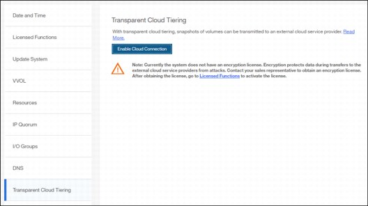
Figure 11-65 Enabling Cloud Tiering
|
Note: It is important to implement encryption before enabling cloud connecting. Encryption protects your data from attacks during the transfer to the external cloud service. Because the HTTP protocol is used to connect to cloud infrastructure, it is likely to start transactions by using the internet. For purposes of this writing, our system does not have encryption enabled.
|
2. Click Next to continue. You must select one of three cloud service providers:
– SoftLayer (now renamed IBM Bluemix)
– OpenStack Switch
– Amazon S3
Figure 11-66 shows the options available.

Figure 11-66 Selecting Cloud service provider
3. In the next window, you must complete the settings of the Cloud Provider, credentials, and security access keys. The required settings can change depending on your cloud service provider. An example of an empty form for an IBM Bluemix connection is shown in Figure 11-67.

Figure 11-67 Entering Cloud Service provider information

Figure 11-68 Cloud Connection summary
5. The cloud credentials can be viewed and updated at any time by using the function icons in left side of the GUI and clicking Settings → Systems → Transparent Cloud Tiering. From this window, you can also verify the status, the data usage statistics, and the upload and download bandwidth limits set to support this functionality.
In the account information window, you can visualize your cloud account information. This panel also enables you to remove the account.

Figure 11-69 Enabled Transparent Cloud Tiering window
11.4.3 Creating cloud snapshots
To manage the cloud snapshots, the IBM Spectrum Virtualize provides a section in the GUI named Cloud Volumes. This section shows you how to add the Volumes that are going to be part of the Transparent Cloud Tiering. As described in 11.3.4, “Transparent Cloud Tiering restrictions” on page 506, cloud snapshot is available only for Volumes that do not have a relationship to the list of restrictions previously mentioned.
Any Volume can be added to the Cloud Volumes. However, snapshots only work for Volumes that are not related to any other copy service.
To create and cloud snapshots, complete these steps:

Figure 11-70 Cloud Volumes menu
2. After Cloud Volumes is selected, a new window opens, and you can use the GUI to select one or more Volumes that you need to enable a cloud snapshot or you can add Volumes to the list, as shown in Figure 11-71.

Figure 11-71 Cloud Volumes window
3. Click Add Volumes to enable cloud-snapshot on Volumes. A new window opens, as shown in Figure 11-72. Select the Volumes that you want to enable Cloud Tiering for and click Next.

Figure 11-72 Adding Volumes to Cloud Tiering
4. IBM Spectrum Virtualize GUI provides two options for you to select. If the first option is selected, the system decides what type of snapshot is created based on previous objects for each selected Volume. If a full copy (full snapshot) of a Volume has already been created, then the system makes an incremental copy of the Volume.
The second option creates a full snapshot of one or more selected Volumes. You can select the second option for a first occurrence of a snapshot and click Finish, as shown in Figure 11-73. You can also select the second option even if another full copy of the Volume already exists.

Figure 11-73 Selecting if a full copy is made or if the system decides
The Cloud Volumes window shows complete information about the Volumes and their snapshots. The GUI shows the following information:
– Name of the Volume
– ID of the Volume assigned by the IBM Spectrum Virtualize
– The size of all snapshots that are taken off the Volume
– The date and time that the last snapshot was created
– The number of snapshots that are taken for every Volume
– The snapshot status
– The restore status
– The Volume group for a set of Volumes
– The Volume UID
Figure 11-74 shows an example of a Cloud Volumes list.

Figure 11-74 Cloud Volumes list example
5. The Actions menu in the Cloud Volumes window allows you to create and manage snapshots. Also, you can use the menu to cancel, disable, and restore snapshots to Volumes as shown in Figure 11-75.

Figure 11-75 Available actions in Cloud Volumes window
11.4.4 Managing cloud snapshots
To manage Volume cloud snapshots, open the Cloud Volumes window, right-click the Volume that you want to manage the snapshots from, and select Manage Cloud Snapshot.
“Managing” a snapshot is actually deleting one or multiple versions. The list of point-in-time copies appear and provide details about their status, type and snapshot date, as shown in Figure 11-76. From this window, an administrator can delete old snapshots (old point-in-time copies) if they are no longer needed. The most recent copy cannot be deleted. If you want to delete the most recent copy, you must first disable Cloud Tiering for the specified Volume.

Figure 11-76 Deleting versions of a Volume’s snapshots
11.4.5 Restoring cloud snapshots
This option allows IBM Spectrum Virtualize to restore snapshots from the cloud to the selected Volumes or to create new Volumes with the restored data.
If the cloud account is shared among systems, IBM Spectrum Virtualize queries the snapshots that are stored in the cloud, and enables you to restore to a new Volume. To restore a Volume’s snapshot, complete the following steps:
1. Open the Cloud Volumes window.

Figure 11-77 Selecting a Volume to restore a snapshot from
3. A list of available snapshots is displayed. The snapshots date (point-in-time), their type (full or incremental), their state and their size are shown, as in Figure 11-78. Select the version that you want to restore and click Next.

Figure 11-78 Selecting a snapshot version to restore
If the snapshot version that you selected has later generations (more recent Snapshot dates), then the newer copies are removed from the cloud.
4. The IBM Spectrum Virtualize GUI provides two options to restore the snapshot from cloud. You can restore the snapshot from cloud directly to the selected Volume, or create a new Volume to restore the data on, as shown in Figure 11-79. Make a selection and click Next.

Figure 11-79 Restoring a snapshot on an existing Volume or on a new Volume
|
Note: Restoring a snapshot on the existing Volume overwrites the data on the Volume. The Volume is taken offline (no read or write access) and the data from the point-in-time copy of the Volume are written. The Volume returns back online when all data is restored from the cloud.
|
5. If you selected the Restore to a new Volume option, then you need to enter the following information for the new Volume to be created with the snapshot data as shown in Figure 11-80:
– Name
– Storage Pool
– Capacity Savings (None, Compressed or Thin-provisioned)
– I/O group
Note that you are not asked to enter the Volume size because the new Volume’s size will be identical to the snapshot copy one.
Enter the settings for the new Volume and click Next.

Figure 11-80 Restoring a snapshot to a new Volume
6. A Summary window is displayed so you can double-check the restoration settings, as shown in Figure 11-81. Click Finish. The system creates a new Volume or overwrites the selected Volume. The more recent snapshots (later versions) of the Volume are deleted from the cloud.

Figure 11-81 Restoring a snapshot summary
If you chose to restore the data from the cloud to a new Volume, the new Volume appears immediately in the Volumes window. However, it is taken offline until all the data from the snapshot is written. The new Volume is totally independent. It is not defined as a target in a FlashCopy mapping with the selected Volume for example. It is not mapped to a host either.
11.5 Volume mirroring and migration options
Volume mirroring is a simple RAID 1-type function that enables a Volume to remain online even when the storage pool that is backing it becomes inaccessible. Volume mirroring is designed to protect the Volume from storage infrastructure failures by seamless mirroring between storage pools.
Volume mirroring is provided by a specific Volume mirroring function in the I/O stack. It cannot be manipulated like a FlashCopy or other types of copy Volumes. However, this feature provides migration functionality, which can be obtained by splitting the mirrored copy from the source or by using the migrate to function. Volume mirroring cannot control backend storage mirroring or replication.
With Volume mirroring, host I/O completes when both copies are written. This feature is enhanced with a tunable latency tolerance. This tolerance provides an option to give preference to losing the redundancy between the two copies. This tunable time-out value is Latency or Redundancy.
The Latency tuning option, which is set with chvdisk -mirrowritepriority latency, is the default. It prioritizes host I/O latency, which yields a preference to host I/O over availability. However, you might need to give preference to redundancy in your environment when availability is more important than I/O response time. Use the chvdisk -mirror writepriority redundancy command to set the redundancy option.
Regardless of which option you choose, Volume mirroring can provide extra protection for your environment.
Migration offers the following options:
•Export to Image mode. By using this option, you can move storage from managed mode to image mode, which is useful if you are using the Storwize system as a migration device. For example, vendor A’s product cannot communicate with vendor B’s product, but you must migrate existing data from vendor A to vendor B. By using Export to Image mode, you can migrate data by using Copy Services functions and then return control to the native array while maintaining access to the hosts.
•Import to Image mode. By using this option, you can import an existing storage MDisk or logical unit number (LUN) with its existing data from an external storage system without putting metadata on it so that the existing data remains intact. After you import it, all copy services functions can be used to migrate the storage to other locations while the data remains accessible to your hosts.
•Volume migration by using Volume mirroring and then by using Split into New Volume. By using this option, you can use the available RAID 1 functions. You create two copies of data that initially have a set relationship (one Volume with two copies, one primary and one secondary) but then break the relationship (two Volumes, both primary and no relationship between them) to make them independent copies of data.
You can use this option to migrate data between storage pools and devices. You might use this option if you want to move Volumes to multiple storage pools. Each Volume can have two copies at a time, which means that you can add only one copy to the original Volume, and then you must split those copies to create another copy of the Volume.
•Volume migration by using move to another pool. By using this option, you can move any Volume between storage pools without any interruption to the host access. This option is a quicker version of the Volume Mirroring and Split into New Volume option. You might use this option if you want to move Volumes in a single step, or you do not have a Volume mirror copy already.
|
Migration: Although these migration methods do not disrupt access, you must take a brief outage to install the host drivers for your IBM SAN Volume Controller if you do not already have them installed.
|
With Volume mirroring, you can move data to different MDisks within the same storage pool or move data between different storage pools. Using Volume mirroring over Volume migration is beneficial because with Volume mirroring, storage pools do not need to have the same extent size as is the case with Volume migration.
|
Note: Volume mirroring does not create a second Volume before you split copies. Volume mirroring adds a second copy of the data under the same Volume. Therefore, you end up having one Volume presented to the host with two copies of data that are connected to this Volume. Only splitting copies creates another Volume, and then both Volumes have only one copy of the data.
|
Starting with V7.3 and the introduction of the new cache architecture, mirrored Volume performance has been significantly improved. Now, lower cache is beneath the Volume mirroring layer, which means that both copies have their own cache.
This approach helps when you have copies of different types, for example generic and compressed, because now both copies use its independent cache and performs its own read prefetch. Destaging of the cache can now be done independently for each copy, so one copy does not affect performance of a second copy.
Also, because the Storwize destage algorithm is MDisk aware, it can tune or adapt the destaging process, depending on MDisk type and usage, for each copy independently.
For more details about Volume Mirroring, see Chapter 7, “Volumes” on page 239.
11.6 Remote Copy
This section describes the Remote Copy services, which are a synchronous remote copy called Metro Mirror (MM), asynchronous remote copy called Global Mirror (GM), and Global Mirror with Change Volumes. Remote Copy in a IBM Spectrum Virtualize system is similar to Remote Copy in the IBM System Storage DS8000 family at a functional level, but the implementation differs.
IBM Spectrum Virtualize provides a single point of control when remote copy is enabled in your network (regardless of the disk subsystems that are used) if those disk subsystems are supported by the system
The general application of remote copy services is to maintain two real-time synchronized copies of a Volume. Often, the two copies are geographically dispersed between two IBM Spectrum Virtualize systems. However, it is possible to use MM or GM within a single system (within an I/O Group). If the master copy fails, you can enable an auxiliary copy for I/O operations.
|
Tips: Intracluster MM/GM uses more resources within the system when compared to an intercluster MM/GM relationship, where resource allocation is shared between the systems. Use intercluster MM/GM when possible. For mirroring Volumes in the same system, it is better to use Volume Mirroring or the FlashCopy feature.
|
A typical application of this function is to set up a dual-site solution that uses two SVC or Storwize systems. The first site is considered the primary site or production site, and the second site is considered the backup site or failover site. The failover site is activated when a failure at the first site is detected.
11.6.1 IBM SAN Volume Controller and Storwize System Layers
An IBM Storwize family system can be in one of the two layers: The replication layer or the storage layer. The system layer affects how the system interacts with IBM SAN Volume Controller systems and other external Storwize family systems. The IBM SAN Volume Controller is always set to replication layer. This parameter cannot be unchanged.
In the storage layer, a Storwize family system has the following characteristics and requirements:
•The system can perform MM and GM replication with other storage-layer systems.
•The system can provide external storage for replication-layer systems or IBM SAN Volume Controller.
•The system cannot use a storage-layer system as external storage.
In the replication layer, an SVC or a Storwize system has the following characteristics and requirements:
•The system can perform MM and GM replication with other replication-layer systems.
•The system cannot provide external storage for a replication-layer system.
•The system can use a storage-layer system as external storage.
A Storwize family system is in the storage layer by default, but the layer can be changed. For example, you might want to change a Storwize V7000 to a replication layer if you want to virtualize other Storwize systems.
|
Note: Before you change the system layer, the following conditions must be met:
•No host object can be configured with worldwide port names (WWPNs) from a Storwize family system.
•No system partnerships can be defined.
•No Storwize family system can be visible on the SAN fabric.
The layer can be changed during normal host I/O.
|
In your IBM Storwize system, use the lssystem command to check the current system layer, as shown in Example 11-2.
Example 11-2 Output from the lssystem command showing the system layer
IBM_Storwize:ITSO_7K:superuser>lssystem
id 000001002140020E
name ITSO_V7K
...
lines omited for brevity
...
easy_tier_acceleration off
has_nas_key no
layer replication
...
|
Note: Consider the following rules for creating remote partnerships between the IBM SAN Volume Controller and Storwize Family systems:
•An IBM SAN Volume Controller is always in the replication layer.
•By default, the IBM Storwize systems are in the storage layer, but can be changed to the replication layer.
•A system can form partnerships only with systems in the same layer.
•Starting in V6.4, an IBM SAN Volume Controller or Storwize system in the replication layer can virtualize an IBM Storwize system in the storage layer.
|
11.6.2 Multiple IBM Spectrum Virtualize systems replication
Each IBM Spectrum Virtualize system can maintain up to three partner system relationships, which enables as many as four systems to be directly associated with each other. This system partnership capability enables the implementation of DR solutions.
|
Note: For more information about restrictions and limitations of native IP replication, see 11.8.2, “IP partnership limitations” on page 557.
|
Figure 11-82 shows an example of a multiple system mirroring configuration.
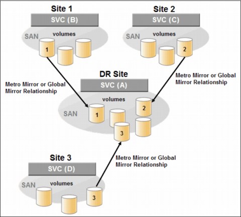
Figure 11-82 Multiple system mirroring configuration example
Supported multiple system mirroring topologies
Multiple system mirroring supports various partnership topologies, as shown in the example in Figure 11-83. This example is a star topology (A → B, A → C, and A → D).

Figure 11-83 Star topology
Figure 11-83 shows four systems in a star topology, with System A at the center. System A can be a central DR site for the three other locations.
By using a star topology, you can migrate applications by using a process, such as the one described in the following example:
1. Suspend application at A.
2. Remove the A → B relationship.
3. Create the A → C relationship (or the B → C relationship).
4. Synchronize to system C, and ensure that A → C is established:
– A → B, A → C, A → D, B → C, B → D, and C → D
– A → B, A → C, and B → C

Figure 11-84 Triangle topology
Figure 11-85 shows an example of an IBM SAN Volume Controller fully connected topology (A → B, A → C, A → D, B → D, and C → D).

Figure 11-85 Fully connected topology
Figure 11-85 is a fully connected mesh in which every system has a partnership to each of the three other systems. This topology enables Volumes to be replicated between any pair of systems, for example A → B, A → C, and B → C.
Figure 11-86 shows a daisy-chain topology.
Figure 11-86 Daisy-chain topology
Although systems can have up to three partnerships, Volumes can be part of only one remote copy relationship, for example A → B.
|
System partnership intermix: All of the preceding topologies are valid for the intermix of the IBM SAN Volume Controller with the Storwize V7000 if the Storwize V7000 is set to the replication layer and running IBM Spectrum Virtualize code 6.3.0 or later.
|
11.6.3 Importance of write ordering
Many applications that use block storage have a requirement to survive failures, such as loss of power or a software crash, and to not lose data that existed before the failure. Because many applications must perform large numbers of update operations in parallel, maintaining write ordering is key to ensure the correct operation of applications after a disruption.
An application that performs many database updates is designed with the concept of dependent writes. With dependent writes, it is important to ensure that an earlier write completed before a later write is started. Reversing or performing the order of writes differently than the application intended can undermine the application’s algorithms and can lead to problems, such as detected or undetected data corruption.
The IBM Spectrum Virtualize Metro Mirror and Global Mirror implementation operates in a manner that is designed to always keep a consistent image at the secondary site. The Global Mirror implementation uses complex algorithms that identify sets of data and number those sets of data in sequence. The data is then applied at the secondary site in the defined sequence.
Operating in this manner ensures that if the relationship is in a Consistent_Synchronized state, the Global Mirror target data is at least crash consistent, and supports quick recovery through application crash recovery facilities.
For more dependent writes information, see 11.1.13, “FlashCopy and image mode Volumes” on page 462.
Remote Copy Consistency Groups
A Remote Copy Consistency Group can contain an arbitrary number of relationships up to the maximum number of MM/GM relationships that is supported by the IBM Spectrum Virtualize system. MM/GM commands can be issued to a Remote Copy Consistency Group.
Therefore, these commands can be issued simultaneously for all MM/GM relationships that are defined within that Consistency Group, or to a single MM/GM relationship that is not part of a Remote Copy Consistency Group. For example, when a startrcconsistgrp command is issued to the Consistency Group, all of the MM/GM relationships in the Consistency Group are started at the same time.
Figure 11-87 shows the concept of Remote Copy Consistency Groups.

Figure 11-87 Remote Copy Consistency Group
Certain uses of MM/GM require the manipulation of more than one relationship. Remote Copy Consistency Groups can group relationships so that they are manipulated in unison.
Consider the following points:
•MM/GM relationships can be part of a Consistency Group, or they can be stand-alone and, therefore, are handled as single instances.
•A Consistency Group can contain zero or more relationships. An empty Consistency Group with zero relationships in it has little purpose until it is assigned its first relationship, except that it has a name.
•All relationships in a Consistency Group must have corresponding master and auxiliary Volumes.
•All relationships in one Consistency Group must be the same type, for example only Metro Mirror or only Global Mirror.
Although Consistency Groups can be used to manipulate sets of relationships that do not need to satisfy these strict rules, this manipulation can lead to undesired side effects. The rules behind a Consistency Group mean that certain configuration commands are prohibited. These configuration commands are not prohibited if the relationship is not part of a Consistency Group.
For example, consider the case of two applications that are independent, yet they are placed into a single Consistency Group. If an error occurs, synchronization is lost and a background copy process is required to recover synchronization. While this process is progressing, MM/GM rejects attempts to enable access to the auxiliary Volumes of either application.
If one application finishes its background copy more quickly than the other application, MM/GM still refuses to grant access to its auxiliary Volumes even though it is safe in this case. The MM/GM policy is to refuse access to the entire Consistency Group if any part of it is inconsistent. Stand-alone relationships and Consistency Groups share a common configuration and state model. All of the relationships in a non-empty Consistency Group have the same state as the Consistency Group.
11.6.4 Remote copy intercluster communication
In the traditional Fibre Channel, the intercluster communication between systems in a Metro Mirror and Global Mirror partnership is performed over the SAN. This section describes this communication path.
For more information about intercluster communication between systems in an IP partnership, see 11.8.6, “States of IP partnership” on page 561.
Zoning
At least 2 FC ports of every node of each system must communicate with each other to create the partnership. Switch zoning is critical to facilitate intercluster communication.
Intercluster communication channels
When an IBM Spectrum Virtualize system partnership is defined on a pair of systems, the following intercluster communication channels are established:
•A single control channel, which is used to exchange and coordinate configuration information
•I/O channels between each of these nodes in the systems
These channels are maintained and updated as nodes and links appear and disappear from the fabric, and are repaired to maintain operation where possible. If communication between the systems is interrupted or lost, an event is logged (and the Metro Mirror and Global Mirror relationships stop).
|
Alerts: You can configure the system to raise Simple Network Management Protocol (SNMP) traps to the enterprise monitoring system to alert on events that indicate an interruption in internode communication occurred.
|
Intercluster links
All IBM SAN Volume Controller nodes maintain a database of other devices that are visible on the fabric. This database is updated as devices appear and disappear.
Devices that advertise themselves as IBM SAN Volume Controller or Storwize V7000 nodes are categorized according to the system to which they belong. Nodes that belong to the same system establish communication channels between themselves and begin to exchange messages to implement clustering and the functional protocols of IBM Spectrum Virtualize.
Nodes that are in separate systems do not exchange messages after initial discovery is complete, unless they are configured together to perform a remote copy relationship.
The intercluster link carries control traffic to coordinate activity between two systems. The link is formed between one node in each system. The traffic between the designated nodes is distributed among logins that exist between those nodes.
If the designated node fails (or all of its logins to the remote system fail), a new node is chosen to carry control traffic. This node change causes the I/O to pause, but it does not put the relationships in a ConsistentStopped state.
|
Note: Use chsystem with -partnerfcportmask to dedicate several FC ports only to system-to-system traffic to ensure that remote copy is not affected by other traffic, such as host-to-node traffic or node-to-node traffic within the same system.
|
11.6.5 Metro Mirror overview
Metro Mirror establishes a synchronous relationship between two Volumes of equal size. The Volumes in a Metro Mirror relationship are referred to as the master (primary) Volume and the auxiliary (secondary) Volume. Traditional FC Metro Mirror is primarily used in a metropolitan area or geographical area, up to a maximum distance of 300 km (186.4 miles) to provide synchronous replication of data.
With synchronous copies, host applications write to the master Volume, but they do not receive confirmation that the write operation completed until the data is written to the auxiliary Volume. This action ensures that both the Volumes have identical data when the copy completes. After the initial copy completes, the Metro Mirror function always maintains a fully synchronized copy of the source data at the target site.
Metro Mirror has the following characteristics:
•Zero recovery point objective (RPO)
•Synchronous
•Production application performance that is affected by round-trip latency
Increased distance directly affects host I/O performance because the writes are synchronous. Use the requirements for application performance when you are selecting your Metro Mirror auxiliary location.
Consistency Groups can be used to maintain data integrity for dependent writes, which is similar to FlashCopy Consistency Groups.
The IBM Spectrum Virtualize provides intracluster and intercluster Metro Mirror.
Intracluster Metro Mirror
Intracluster Metro Mirror performs the intracluster copying of a Volume, in which both Volumes belong to the same system and I/O Group within the system. Because it is within the same I/O Group, there must be sufficient bitmap space within the I/O Group for both sets of Volumes and licensing on the system.
|
Important: Performing Metro Mirror across I/O Groups within a system is not supported.
|
Intercluster Metro Mirror
Intercluster Metro Mirror performs intercluster copying of a Volume, in which one Volume belongs to a system and the other Volume belongs to a separate system.
Two IBM Spectrum Virtualize systems must be defined in a partnership, which must be performed on both systems to establish a fully functional Metro Mirror partnership.
By using standard single-mode connections, the supported distance between two systems in a Metro Mirror partnership is 10 km (6.2 miles), although greater distances can be achieved by using extenders. For extended distance solutions, contact your IBM representative.
|
Limit: When a local fabric and a remote fabric are connected for Metro Mirror purposes, the inter-switch link (ISL) hop count between a local node and a remote node cannot exceed seven.
|
11.6.6 Synchronous remote copy
Metro Mirror is a fully synchronous remote copy technique that ensures that writes are committed at both the master and auxiliary Volumes before write completion is acknowledged to the host, but only if writes to the auxiliary Volumes are possible.
Events, such as a loss of connectivity between systems, can cause mirrored writes from the master Volume and the auxiliary Volume to fail. In that case, Metro Mirror suspends writes to the auxiliary Volume and enables I/O to the master Volume to continue to avoid affecting the operation of the master Volumes.
Figure 11-88 shows how a write to the master Volume is mirrored to the cache of the auxiliary Volume before an acknowledgment of the write is sent back to the host that issued the write. This process ensures that the auxiliary is synchronized in real time if it is needed in a failover situation.

Figure 11-88 Write on Volume in Metro Mirror relationship
However, this process also means that the application is exposed to the latency and bandwidth limitations (if any) of the communication link between the master and auxiliary Volumes. This process might lead to unacceptable application performance, particularly when placed under peak load. Therefore, the use of traditional Fibre Channel Metro Mirror has distance limitations that are based on your performance requirements. IBM Spectrum Virtualize does not support more than 300 km (186.4 miles).
11.6.7 Metro Mirror features
The IBM Spectrum Virtualize Metro Mirror function supports the following features:
•Synchronous remote copy of Volumes that are dispersed over metropolitan distances.
•The Metro Mirror relationships between Volume pairs, with each Volume in a pair that is managed by a Storwize V7000 system or IBM SAN Volume Controller system (requires V6.3.0 or later).
•Supports intracluster Metro Mirror where both Volumes belong to the same system (and I/O Group).
•IBM Spectrum Virtualize supports intercluster Metro Mirror where each Volume belongs to a separate system. You can configure a specific system for partnership with another system. All intercluster Metro Mirror processing occurs between two IBM Spectrum Virtualize systems that are configured in a partnership.
•Intercluster and intracluster Metro Mirror can be used concurrently.
•IBM Spectrum Virtualize does not require that a control network or fabric is installed to manage Metro Mirror. For intercluster Metro Mirror, the system maintains a control link between two systems. This control link is used to control the state and coordinate updates at either end. The control link is implemented on top of the same FC fabric connection that the system uses for Metro Mirror I/O.
•IBM Spectrum Virtualize implements a configuration model that maintains the Metro Mirror configuration and state through major events, such as failover, recovery, and resynchronization, to minimize user configuration action through these events.
IBM Spectrum Virtualize supports the resynchronization of changed data so that write failures that occur on the master or auxiliary Volumes do not require a complete resynchronization of the relationship.
11.6.8 Metro Mirror attributes
The Metro Mirror function in IBM Spectrum Virtualize possesses the following attributes:
•A partnership is created between two IBM Spectrum Virtualize systems operating in the replication layer (for intercluster Metro Mirror).
•A Metro Mirror relationship is created between two Volumes of the same size.
•To manage multiple Metro Mirror relationships as one entity, relationships can be made part of a Metro Mirror Consistency Group, which ensures data consistency across multiple Metro Mirror relationships and provides ease of management.
•When a Metro Mirror relationship is started and when the background copy completes, the relationship becomes consistent and synchronized.
•After the relationship is synchronized, the auxiliary Volume holds a copy of the production data at the primary, which can be used for DR.
•The auxiliary Volume is in read-only mode when relationship is active.
•To access the auxiliary Volume, the Metro Mirror relationship must be stopped with the access option enabled before write I/O is allowed to the auxiliary.
•The remote host server is mapped to the auxiliary Volume, and the disk is available for I/O.
11.6.9 Practical use of Metro Mirror
The master Volume is the production Volume, and updates to this copy are mirrored in real time to the auxiliary Volume. The contents of the auxiliary Volume that existed when the relationship was created are deleted.
|
Switching copy direction: The copy direction for a Metro Mirror relationship can be switched so that the auxiliary Volume becomes the master, and the master Volume becomes the auxiliary, which is similar to the FlashCopy restore option. However, although the FlashCopy target Volume can operate in read/write mode, the target Volume of the started remote copy is always in read-only mode.
|
While the Metro Mirror relationship is active, the auxiliary Volume is not accessible for host application write I/O at any time. The IBM Storwize V7000 allows read-only access to the auxiliary Volume when it contains a consistent image. Storwize allows boot time operating system discovery to complete without an error, so that any hosts at the secondary site can be ready to start the applications with minimum delay, if required.
For example, many operating systems must read LBA zero to configure a logical unit. Although read access is allowed at the auxiliary in practice, the data on the auxiliary Volumes cannot be read by a host because most operating systems write a “dirty bit” to the file system when it is mounted. Because this write operation is not allowed on the auxiliary Volume, the Volume cannot be mounted.
This access is provided only where consistency can be ensured. However, coherency cannot be maintained between reads that are performed at the auxiliary and later write I/Os that are performed at the master.
To enable access to the auxiliary Volume for host operations, you must stop the Metro Mirror relationship by specifying the -access parameter. While access to the auxiliary Volume for host operations is enabled, the host must be instructed to mount the Volume before the application can be started, or instructed to perform a recovery process.
For example, the Metro Mirror requirement to enable the auxiliary copy for access differentiates it from third-party mirroring software on the host, which aims to emulate a single, reliable disk regardless of what system is accessing it. Metro Mirror retains the property that there are two Volumes in existence, but it suppresses one Volume while the copy is being maintained.
The use of an auxiliary copy demands a conscious policy decision by the administrator that a failover is required, and that the tasks to be performed on the host that is involved in establishing the operation on the auxiliary copy are substantial. The goal is to make this copy rapid (much faster when compared to recovering from a backup copy) but not seamless.
The failover process can be automated through failover management software. The IBM Storwize V7000 provides SNMP traps and programming (or scripting) for the CLI to enable this automation.
11.6.10 Global Mirror overview
This section describes the Global Mirror copy service, which is an asynchronous remote copy service. This service provides and maintains a consistent mirrored copy of a source Volume to a target Volume.
Global Mirror establishes a Global Mirror relationship between two Volumes of equal size. The Volumes in a Global Mirror relationship are referred to as the master (source) Volume and the auxiliary (target) Volume, which is the same as Metro Mirror. Consistency Groups can be used to maintain data integrity for dependent writes, which is similar to FlashCopy Consistency Groups.
Global Mirror writes data to the auxiliary Volume asynchronously, which means that host writes to the master Volume provide the host with confirmation that the write is complete before the I/O completes on the auxiliary Volume.
Global Mirror has the following characteristics:
•Near-zero RPO
•Asynchronous
•Production application performance that is affected by I/O sequencing preparation time
Intracluster Global Mirror
Although Global Mirror is available for intracluster, it has no functional value for production use. Intracluster Metro Mirror provides the same capability with less processor use. However, leaving this functionality in place simplifies testing and supports client experimentation and testing (for example, to validate server failover on a single test system). As with Intracluster Metro Mirror, you must consider the increase in the license requirement because source and target exist on the same IBM Spectrum Virtualize system.
Intercluster Global Mirror
Intercluster Global Mirror operations require a pair of IBM Spectrum Virtualize systems that are connected by several intercluster links. The two systems must be defined in a partnership to establish a fully functional Global Mirror relationship.
|
Limit: When a local fabric and a remote fabric are connected for Global Mirror purposes, the ISL hop count between a local node and a remote node must not exceed seven hops.
|
11.6.11 Asynchronous remote copy
Global Mirror is an asynchronous remote copy technique. In asynchronous remote copy, the write operations are completed on the primary site and the write acknowledgment is sent to the host before it is received at the secondary site. An update of this write operation is sent to the secondary site at a later stage, which provides the capability to perform remote copy over distances that exceed the limitations of synchronous remote copy.
The Global Mirror function provides the same function as Metro Mirror remote copy, but over long-distance links with higher latency without requiring the hosts to wait for the full round-trip delay of the long-distance link.
Figure 11-89 shows that a write operation to the master Volume is acknowledged back to the host that is issuing the write before the write operation is mirrored to the cache for the auxiliary Volume.

Figure 11-89 Global Mirror write sequence
The Global Mirror algorithms maintain a consistent image on the auxiliary always. They achieve this consistent image by identifying sets of I/Os that are active concurrently at the master, assigning an order to those sets, and applying those sets of I/Os in the assigned order at the secondary. As a result, Global Mirror maintains the features of Write Ordering and Read Stability.
The multiple I/Os within a single set are applied concurrently. The process that marshals the sequential sets of I/Os operates at the secondary system. Therefore, the process is not subject to the latency of the long-distance link. These two elements of the protocol ensure that the throughput of the total system can be grown by increasing system size while maintaining consistency across a growing data set.
Global Mirror write I/O from production system to a secondary system requires serialization and sequence-tagging before being sent across the network to a remote site (to maintain a write-order consistent copy of data).
To avoid affecting the production site, IBM Spectrum Virtualize supports more parallelism in processing and managing Global Mirror writes on the secondary system by using the following methods:
•Secondary system nodes store replication writes in new redundant non-volatile cache
•Cache content details are shared between nodes
•Cache content details are batched together to make node-to-node latency less of an issue
•Nodes intelligently apply these batches in parallel as soon as possible
•Nodes internally manage and optimize Global Mirror secondary write I/O processing
In a failover scenario where the secondary site must become the master source of data, certain updates might be missing at the secondary site. Therefore, any applications that use this data must have an external mechanism for recovering the missing updates and reapplying them; for example, a transaction log replay.
Global Mirror is supported over FC, FC over IP (FCIP), FC over Ethernet (FCoE), and native IP connections. The maximum distance cannot exceed 80 ms round trip, which is about 4000 km (2485.48 miles) between mirrored systems. But starting with IBM Spectrum Virtualize V7.4, this distance was significantly increased for certain IBM Storwize Gen2 and IBM SAN Volume Controller configurations. Figure 11-90 shows the current supported distances for Global Mirror remote copy.

Figure 11-90 Supported Global Mirror distances
11.6.12 Global Mirror features
IBM Spectrum Virtualize Global Mirror supports the following features:
•Asynchronous remote copy of Volumes that are dispersed over metropolitan-scale distances.
•IBM Spectrum Virtualize implements the Global Mirror relationship between a Volume pair, with each Volume in the pair being managed by an IBM Spectrum Virtualize system.
•IBM Spectrum Virtualize supports intracluster Global Mirror where both Volumes belong to the same system (and I/O Group).
•An IBM Spectrum Virtualize system can be configured for partnership with 1 - 3 other systems. For more information about IP partnership restrictions, see 11.8.2, “IP partnership limitations” on page 557.
•Intercluster and intracluster Global Mirror can be used concurrently, but not for the
same Volume.
same Volume.
•IBM Spectrum Virtualize does not require a control network or fabric to be installed to manage Global Mirror. For intercluster Global Mirror, the system maintains a control link between the two systems. This control link is used to control the state and to coordinate the updates at either end. The control link is implemented on top of the same FC fabric connection that the system uses for Global Mirror I/O.
•IBM Spectrum Virtualize implements a configuration model that maintains the Global Mirror configuration and state through major events, such as failover, recovery, and resynchronization, to minimize user configuration action through these events.
•IBM Spectrum Virtualize implements flexible resynchronization support, enabling it to resynchronize Volume pairs that experienced write I/Os to both disks, and to resynchronize only those regions that changed.
•An optional feature for Global Mirror is a delay simulation to be applied on writes that are sent to auxiliary Volumes. It is useful in intracluster scenarios for testing purposes.
Colliding writes
Before V4.3.1, the Global Mirror algorithm required that only a single write is active on any 512-byte logical block address (LBA) of a Volume. If a further write is received from a host while the auxiliary write is still active (even though the master write might complete), the new host write is delayed until the auxiliary write is complete. This restriction is needed if a series of writes to the auxiliary must be tried again (which is called reconstruction). Conceptually, the data for reconstruction comes from the master Volume.
If multiple writes are allowed to be applied to the master for a sector, only the most recent write gets the correct data during reconstruction. If reconstruction is interrupted for any reason, the intermediate state of the auxiliary is inconsistent. Applications that deliver such write activity do not achieve the performance that Global Mirror is intended to support. A Volume statistic is maintained about the frequency of these collisions.
An attempt is made to allow multiple writes to a single location to be outstanding in the Global Mirror algorithm. There is still a need for master writes to be serialized, and the intermediate states of the master data must be kept in a non-volatile journal while the writes are outstanding to maintain the correct write ordering during reconstruction. Reconstruction must never overwrite data on the auxiliary with an earlier version. The Volume statistic that is monitoring colliding writes is now limited to those writes that are not affected by this change.
Figure 11-91 shows a colliding write sequence example.

Figure 11-91 Colliding writes example
The following numbers correspond to the numbers that are shown in Figure 11-91:
•(1) The first write is performed from the host to LBA X.
•(2) The host is provided acknowledgment that the write completed even though the mirrored write to the auxiliary Volume is not yet complete.
•(1’) and (2’) occur asynchronously with the first write.
•(3) The second write is performed from the host also to LBA X. If this write occurs before (2’), the write is written to the journal file.
•(4) The host is provided acknowledgment that the second write is complete.
Delay simulation
An optional feature for Global Mirror enables a delay simulation to be applied on writes that are sent to auxiliary Volumes. This feature enables you to perform testing that detects colliding writes. Therefore, you can use this feature to test an application before the full deployment of the feature. The feature can be enabled separately for each of the intracluster or intercluster Global Mirrors.
You specify the delay setting by using the chsystem command and view the delay by using the lssystem command. The gm_intra_cluster_delay_simulation field expresses the amount of time that intracluster auxiliary I/Os are delayed. The gm_inter_cluster_delay_simulation field expresses the amount of time that intercluster auxiliary I/Os are delayed. A value of zero disables the feature.
|
Tip: If you are experiencing repeated problems with the delay on your link, make sure that the delay simulator was properly disabled.
|
11.6.13 Using Change Volumes with Global Mirror
Global Mirror is designed to achieve an RPO as low as possible so that data is as up-to-date as possible. This design places several strict requirements on your infrastructure. In certain situations with low network link quality, congested hosts, or overloaded hosts, you might be affected by multiple 1920 congestion errors.
Congestion errors happen in the following primary situations:
•Congestion at the source site through the host or network
•Congestion in the network link or network path
•Congestion at the target site through the host or network
Global Mirror has functionality that is designed to address the following conditions, which might negatively affect certain Global Mirror implementations:
•The estimation of the bandwidth requirements tends to be complex.
•Ensuring that the latency and bandwidth requirements can be met is often difficult.
•Congested hosts on the source or target site can cause disruption.
•Congested network links can cause disruption with only intermittent peaks.
To address these issues, Change Volumes were added as an option for Global Mirror relationships. Change Volumes use the FlashCopy functionality, but they cannot be manipulated as FlashCopy Volumes because they are for a special purpose only. Change Volumes replicate point-in-time images on a cycling period. The default is 300 seconds.
Your change rate needs to include only the condition of the data at the point-in-time that the image was taken, rather than all the updates during the period. The use of this function can provide significant reductions in replication Volume.
Global Mirror with Change Volumes has the following characteristics:
•Larger RPO
•Point-in-time copies
•Asynchronous
•Possible system performance resource requirements because point-in-time copies are created locally
Figure 11-92 shows a simple Global Mirror relationship without Change Volumes.

Figure 11-92 Global Mirror without Change Volumes
With Change Volumes, this environment looks as it is shown in Figure 11-93.

Figure 11-93 Global Mirror with Change Volumes
With Change Volumes, a FlashCopy mapping exists between the primary Volume and the primary Change Volume. The mapping is updated on the cycling period (60 seconds to one day). The primary Change Volume is then replicated to the secondary Global Mirror Volume at the target site, which is then captured in another Change Volume on the target site. This approach provides an always consistent image at the target site and protects your data from being inconsistent during resynchronization.
For more information about IBM FlashCopy, see 11.1, “IBM FlashCopy” on page 438.
You can adjust the cycling period by using the chrcrelationship -cycleperiodseconds
<60 - 86400> command from the CLI. If a copy does not complete in the cycle period, the next cycle does not start until the prior cycle completes. For this reason, the use of Change Volumes gives you the following possibilities for RPO:
<60 - 86400> command from the CLI. If a copy does not complete in the cycle period, the next cycle does not start until the prior cycle completes. For this reason, the use of Change Volumes gives you the following possibilities for RPO:
•If your replication completes in the cycling period, your RPO is twice the cycling period.
•If your replication does not complete within the cycling period, RPO is twice the completion time. The next cycling period starts immediately after the prior cycling period is finished.
Carefully consider your business requirements versus the performance of Global Mirror with Change Volumes. Global Mirror with Change Volumes increases the intercluster traffic for more frequent cycling periods. Therefore, selecting the shortest cycle periods possible is not always the answer. In most cases, the default must meet requirements and perform well.
|
Important: When you create your Global Mirror Volumes with Change Volumes, make sure that you remember to select the Change Volume on the auxiliary (target) site. Failure to do so leaves you exposed during a resynchronization operation.
|
11.6.14 Distribution of work among nodes
For the best performance, MM/GM Volumes must have their preferred nodes evenly distributed among the nodes of the systems. Each Volume within an I/O Group has a preferred node property that can be used to balance the I/O load between nodes in that group. MM/GM also uses this property to route I/O between systems.
If this preferred practice is not maintained, such as if source Volumes are assigned to only one node in the I/O group, you can change the preferred node for each Volume to distribute Volumes evenly between the nodes. You can also change the preferred node for Volumes that are in a remote copy relationship without affecting the host I/O to a particular Volume.
The remote copy relationship type does not matter. The remote copy relationship type can be MM, GM, or GM with Change Volumes. You can change the preferred node both to the source and target Volumes that are participating in the remote copy relationship.
11.6.15 Background copy performance
The background copy performance is subject to sufficient RAID controller bandwidth. Performance is also subject to other potential bottlenecks, such as the intercluster fabric, and possible contention from host I/O for the IBM Spectrum Virtualize system bandwidth resources.
Background copy I/O is scheduled to avoid bursts of activity that could have an adverse effect on system behavior. An entire grain of tracks on one Volume is processed at around the same time, but not as a single I/O. Double buffering is used to try to use sequential performance within a grain. However, the next grain within the Volume might not be scheduled for some time. Multiple grains might be copied simultaneously, and might be enough to satisfy the requested rate, unless the available resources cannot sustain the requested rate.
Global Mirror paces the rate at which background copy is performed by the appropriate relationships. Background copy occurs on relationships that are in the InconsistentCopying state with a status of Online.
The quota of background copy (configured on the intercluster link) is divided evenly between all nodes that are performing background copy for one of the eligible relationships. This allocation is made irrespective of the number of disks for which the node is responsible. Each node in turn divides its allocation evenly between the multiple relationships that are performing a background copy.
The default value of the background copy is 25 megabytes per second (MBps), per Volume.
|
Important: The background copy value is a system-wide parameter that can be changed dynamically, but only on a per-system basis and not on a per-relationship basis. Therefore, the copy rate of all relationships changes when this value is increased or decreased. In systems with many remote copy relationships, increasing this value might affect overall system or intercluster link performance. The background copy rate can be changed to
1 - 1000 MBps. |
11.6.16 Thin-provisioned background copy
Metro Mirror and Global Mirror relationships preserve the space-efficiency of the master. Conceptually, the background copy process detects a deallocated region of the master and sends a special zero buffer to the auxiliary.
If the auxiliary Volume is thin-provisioned and the region is deallocated, the special buffer prevents a write and, therefore, an allocation. If the auxiliary Volume is not thin-provisioned or the region in question is an allocated region of a thin-provisioned Volume, a buffer of “real” zeros is synthesized on the auxiliary and written as normal.
11.6.17 Methods of synchronization
This section describes two methods that can be used to establish a synchronized relationship.
Full synchronization after creation
The full synchronization after creation method is the default method. It is the simplest method in that it requires no administrative activity apart from issuing the necessary commands. However, in certain environments, the available bandwidth can make this method unsuitable.
Use the following command sequence for a single relationship:
•Run mkrcrelationship without specifying the -sync option.
•Run startrcrelationship without specifying the -clean option.
Synchronized before creation
In this method, the administrator must ensure that the master and auxiliary Volumes contain identical data before creating the relationship by using the following technique:
•Both disks are created with the security delete feature to make all data zero.
•A complete tape image (or other method of moving data) is copied from one disk to the other disk.
With this technique, do not allow I/O on the master or auxiliary before the relationship
is established. Then, the administrator must run the following commands:
is established. Then, the administrator must run the following commands:
•Run mkrcrelationship with the -sync flag.
•Run startrcrelationship without the -clean flag.
|
Important: Failure to perform these steps correctly can cause MM/GM to report the relationship as consistent when it is not, possibly causing a data loss or data integrity exposure for hosts accessing data on the auxiliary Volume.
|
11.6.18 Practical use of Global Mirror
The practical use of Global Mirror is similar to the Metro Mirror described in 11.6.9, “Practical use of Metro Mirror” on page 530. The main difference between the two remote copy modes is that Global Mirror and Global Mirror with Change Volumes are mostly used on much larger distances than Metro Mirror. Weak link quality or insufficient bandwidth between the primary and secondary sites can also be a reason to prefer asynchronous Global Mirror over synchronous Metro Mirror. Otherwise, the use cases for Metro Mirror and Global Mirror are the same.
11.6.19 Spectrum Virtualize HyperSwap topology
The IBM HyperSwap topology is based on Spectrum Virtualize Remote Copy mechanisms. It is also referred to as “active-active relationship” in this document.
You can create an HyperSwap topology system configuration where each I/O group in the system is physically on a different site. These configurations can be used to maintain access to data on the system when power failures or site-wide outages occur.
In a HyperSwap configuration, each site is defined as an independent failure domain. If one site experiences a failure, then the other site can continue to operate without disruption. You must also configure a third site to host a quorum device or IP quorum application that provides an automatic tie-break in case of a link failure between the two main sites. The main site can be in the same room or across rooms in the data center, buildings on the same campus, or buildings in different cities. Different kinds of sites protect against different types of failures.
For more details about HyperSwap implementation and best practices, see IBM Storwize V7000, Spectrum Virtualize, HyperSwap, and VMware Implementation, SG24-8317.
11.6.20 Consistency Protection for GM/MM
Metro Mirror, Global Mirror, Global Mirror with change volumes, and HyperSwap Copy Services functions create remote copy or remote replication relationships between volumes or consistency groups. If the secondary volume in a Copy Services relationship becomes unavailable to the primary volume, the system maintains the relationship. However, the data might become out of sync when the secondary volume becomes available.
Since V7.8, it is possible to create a FlashCopy mapping (Change Volume) for a remote copy target Volume to maintain a consistent image of the secondary volume. The system recognizes it as a Consistency Protection and a link failure or an offline secondary Volume event is handled differently now.
When Consistency Protection is configured, the relationship between the primary and secondary volumes does not stop if the link goes down or the secondary volume is offline. The relationship does not go in to the Consistent stopped status. Instead, the system uses the secondary change volume to automatically copy the previous consistent state of the secondary volume. The relationship automatically moves to the Consistent copying status as the system resynchronizes and protects the consistency of the data. The relationship status changes to Consistent synchronized when the resynchronization process completes. The relationship automatically resumes replication after the temporary loss of connectivity.
Change Volumes used for Consistency Protection are not visible and manageable from the GUI because they are used for Consistency Protection internal behavior only.
It is not required to configure a secondary change volume on a Metro Mirror or Global Mirror (without cycling) relationship. However, if the link goes down or the secondary volume is offline, the relationship goes in to the Consistent stopped status. If write operations take place on either the primary or secondary volume, the data is no longer synchronized (Out of sync).
Consistency protection must be enabled on all relationships in a consistency group. Every relationship in a consistency group must be configured with a secondary change volume. If a secondary change volume is not configured on one relationship, the entire consistency group stops with a 1720 error if host I/O is processed when the link is down or any secondary volume in the consistency group is offline. All relationships in the consistency group are unable to retain a consistent copy during resynchronization.
The option to add consistency protection is selected by default when Metro Mirror or Global Mirror relationships are created. The option must be cleared to create Metro Mirror or Global Mirror relationships without consistency protection.
11.6.21 Valid combinations of FlashCopy, Metro Mirror, and Global Mirror
Table 11-10 lists the combinations of FlashCopy and Metro Mirror or Global Mirror functions that are valid for a single Volume.
Table 11-10 Valid combination for a single Volume
|
FlashCopy
|
Metro Mirror or Global Mirror source
|
Metro Mirror or Global Mirror target
|
|
FlashCopy Source
|
Supported
|
Supported
|
|
FlashCopy Target
|
Supported
|
Not supported
|
11.6.22 Remote Copy configuration limits
Table 11-11 lists the Metro Mirror and Global Mirror configuration limits.
Table 11-11 Metro Mirror configuration limits
|
Parameter
|
Value
|
|
Number of Metro Mirror or Global Mirror Consistency Groups per system
|
256
|
|
Number of Metro Mirror or Global Mirror relationships per system
|
8192
|
|
Number of Metro Mirror or Global Mirror relationships per Consistency Group
|
8192
|
|
Total Volume size per I/O Group
|
There is a per I/O Group limit of 1024 terabytes (TB) on the quantity of master and auxiliary Volume address spaces that can participate in Metro Mirror and Global Mirror relationships. This maximum configuration uses all 512 MiB of bitmap space for the I/O Group and allows 10 MiB of space for all remaining copy services features.
|
11.6.23 Remote Copy states and events
This section describes the various states of a MM/GM relationship and the conditions that cause them to change. In Figure 11-94, the MM/GM relationship diagram shows an overview of the status that can apply to a MM/GM relationship in a connected state.

Figure 11-94 Metro Mirror or Global Mirror mapping state diagram
When the MM/GM relationship is created, you can specify whether the auxiliary Volume is already in sync with the master Volume, and the background copy process is then skipped. This capability is useful when MM/GM relationships are established for Volumes that were created with the format option.
The following step identifiers are shown in Figure 11-94:
•Step 1:
a. The MM/GM relationship is created with the -sync option, and the MM/GM relationship enters the ConsistentStopped state.
b. The MM/GM relationship is created without specifying that the master and auxiliary Volumes are in sync, and the MM/GM relationship enters the InconsistentStopped state.
•Step 2:
a. When a MM/GM relationship is started in the ConsistentStopped state, the MM/GM relationship enters the ConsistentSynchronized state. Therefore, no updates (write I/O) were performed on the master Volume while in the ConsistentStopped state. Otherwise, the -force option must be specified, and the MM/GM relationship then enters the InconsistentCopying state while the background copy is started.
b. When a MM/GM relationship is started in the InconsistentStopped state, the MM/GM relationship enters the InconsistentCopying state while the background copy is started.
•Step 3:
When the background copy completes, the MM/GM relationship changes from the InconsistentCopying state to the ConsistentSynchronized state.
•Step 4:
a. When a MM/GM relationship is stopped in the ConsistentSynchronized state, the MM/GM relationship enters the Idling state when you specify the -access option, which enables write I/O on the auxiliary Volume.
b. When a MM/GM relationship is stopped in the ConsistentSynchronized state without an -access parameter, the auxiliary Volumes remain read-only and the state of the relationship changes to ConsistentStopped.
c. To enable write I/O on the auxiliary Volume, when the MM/GM relationship is in the ConsistentStopped state, issue the svctask stoprcrelationship command, which specifies the -access option, and the MM/GM relationship enters the Idling state.
•Step 5:
a. When a MM/GM relationship is started from the Idling state, you must specify the -primary argument to set the copy direction. If no write I/O was performed (to the master or auxiliary Volume) while in the Idling state, the MM/GM relationship enters the ConsistentSynchronized state.
b. If write I/O was performed to the master or auxiliary Volume, the -force option must be specified and the MM/GM relationship then enters the InconsistentCopying state while the background copy is started. The background process copies only the data that changed on the primary Volume while the relationship was stopped.
Stop on Error
When a MM/GM relationship is stopped (intentionally, or because of an error), the state changes. For example, the MM/GM relationships in the ConsistentSynchronized state enter the ConsistentStopped state, and the MM/GM relationships in the InconsistentCopying state enter the InconsistentStopped state.
If the connection is broken between the two systems that are in a partnership, all (intercluster) MM/GM relationships enter a Disconnected state. For more information, see “Connected versus disconnected” on page 542.
|
Common states: Stand-alone relationships and Consistency Groups share a common configuration and state model. All MM/GM relationships in a Consistency Group have the same state as the Consistency Group.
|
State overview
In the following sections, we provide an overview of the various MM/GM states.
Connected versus disconnected
Under certain error scenarios (for example, a power failure at one site that causes one complete system to disappear), communications between two systems in an MM/GM relationship can be lost. Alternatively, the fabric connection between the two systems might fail, which leaves the two systems that are running but cannot communicate with each other.
When the two systems can communicate, the systems and the relationships that spans them are described as connected. When they cannot communicate, the systems and the relationships spanning them are described as disconnected.
In this state, both systems are left with fragmented relationships and are limited regarding the configuration commands that can be performed. The disconnected relationships are portrayed as having a changed state. The new states describe what is known about the relationship and the configuration commands that are permitted.
When the systems can communicate again, the relationships are reconnected. MM/GM automatically reconciles the two state fragments, considering any configuration or other event that occurred while the relationship was disconnected. As a result, the relationship can return to the state that it was in when it became disconnected, or it can enter a new state.
Relationships that are configured between Volumes in the same IBM Storwize V7000 system (intracluster) are never described as being in a disconnected state.
Consistent versus inconsistent
Relationships that contain Volumes that are operating as secondaries can be described as being consistent or inconsistent. Consistency Groups that contain relationships can also be described as being consistent or inconsistent. The consistent or inconsistent property describes the relationship of the data on the auxiliary to the data on the master Volume. It can be considered a property of the auxiliary Volume.
An auxiliary Volume is described as consistent if it contains data that can be read by a host system from the master if power failed at an imaginary point while I/O was in progress, and power was later restored. This imaginary point is defined as the recovery point.
The requirements for consistency are expressed regarding activity at the master up to the recovery point. The auxiliary Volume contains the data from all of the writes to the master for which the host received successful completion and that data was not overwritten by a subsequent write (before the recovery point).
Consider writes for which the host did not receive a successful completion (that is, it received bad completion or no completion at all). If the host then performed a read from the master of that data that returned successful completion and no later write was sent (before the recovery point), the auxiliary contains the same data as the data that was returned by the read from
the master.
the master.
From the point of view of an application, consistency means that an auxiliary Volume contains the same data as the master Volume at the recovery point (the time at which the imaginary power failure occurred). If an application is designed to cope with an unexpected power failure, this assurance of consistency means that the application can use the auxiliary and begin operation as though it was restarted after the hypothetical power failure. Again, maintaining the application write ordering is the key property of consistency.
For more information about dependent writes, see 11.1.13, “FlashCopy and image mode Volumes” on page 462.
If a relationship (or set of relationships) is inconsistent and an attempt is made to start an application by using the data in the secondaries, the following outcomes are possible:
•The application might decide that the data is corrupted and crash or exit with an event code.
•The application might fail to detect that the data is corrupted and return erroneous data.
•The application might work without a problem.
Because of the risk of data corruption, and in particular undetected data corruption, MM/GM strongly enforces the concept of consistency and prohibits access to inconsistent data.
Consistency as a concept can be applied to a single relationship or a set of relationships in a Consistency Group. Write ordering is a concept that an application can maintain across several disks that are accessed through multiple systems. Therefore, consistency must operate across all of those disks.
When you are deciding how to use Consistency Groups, the administrator must consider the scope of an application’s data and consider all of the interdependent systems that communicate and exchange information.
If two programs or systems communicate and store details as a result of the information that is exchanged, either of the following actions might occur:
•All of the data that is accessed by the group of systems must be placed into a single Consistency Group.
•The systems must be recovered independently (each within its own Consistency Group). Then, each system must perform recovery with the other applications to become consistent with them.
Consistent versus synchronized
A copy that is consistent and up-to-date is described as synchronized. In a synchronized relationship, the master and auxiliary Volumes differ only in regions where writes are outstanding from the host.
Consistency does not mean that the data is up-to-date. A copy can be consistent and yet contain data that was frozen at a point in the past. Write I/O might continue to a master but not be copied to the auxiliary. This state arises when it becomes impossible to keep data up-to-date and maintain consistency. An example is a loss of communication between systems when you are writing to the auxiliary.
When communication is lost for an extended period and Consistency Protection was not enabled, MM/GM tracks the changes that occurred on the master, but not the order or the details of such changes (write data). When communication is restored, it is impossible to synchronize the auxiliary without sending write data to the auxiliary out of order. Therefore, consistency is lost.
|
Note: MM/GM relationships with Consistency Protection enabled use a point-in-time copy mechanism (FlashCopy) to keep a consistent copy of the auxiliary. The relationships stay in a consistent state, although not synchronized, even if communication is lost. For details about Consistency Protection, see 11.6.20, “Consistency Protection for GM/MM” on page 539.
|
Detailed states
The following sections describe the states that are portrayed to the user for either Consistency Groups or relationships. They also describe information that is available in each state. The major states are designed to provide guidance about the available configuration commands.
InconsistentStopped
InconsistentStopped is a connected state. In this state, the master is accessible for read and write I/O, but the auxiliary is not accessible for read or write I/O. A copy process must be started to make the auxiliary consistent. This state is entered when the relationship or Consistency Group was InconsistentCopying and suffered a persistent error or received a stop command that caused the copy process to stop.
A start command causes the relationship or Consistency Group to move to the InconsistentCopying state. A stop command is accepted, but has no effect.
If the relationship or Consistency Group becomes disconnected, the auxiliary side makes the transition to InconsistentDisconnected. The master side changes to IdlingDisconnected.
InconsistentCopying
InconsistentCopying is a connected state. In this state, the master is accessible for read and write I/O, but the auxiliary is not accessible for read or write I/O. This state is entered after a start command is issued to an InconsistentStopped relationship or a Consistency Group.
It is also entered when a forced start is issued to an Idling or ConsistentStopped relationship or Consistency Group. In this state, a background copy process runs that copies data from the master to the auxiliary Volume.
In the absence of errors, an InconsistentCopying relationship is active, and the copy progress increases until the copy process completes. In certain error situations, the copy progress might freeze or even regress.
A persistent error or stop command places the relationship or Consistency Group into an InconsistentStopped state. A start command is accepted but has no effect.
If the background copy process completes on a stand-alone relationship or on all relationships for a Consistency Group, the relationship or Consistency Group changes to the ConsistentSynchronized state.
If the relationship or Consistency Group becomes disconnected, the auxiliary side changes to InconsistentDisconnected. The master side changes to IdlingDisconnected.
ConsistentStopped
ConsistentStopped is a connected state. In this state, the auxiliary contains a consistent image, but it might be out-of-date in relation to the master. This state can arise when a relationship was in a ConsistentSynchronized state and experienced an error that forces a Consistency Freeze. It can also arise when a relationship is created with a CreateConsistentFlag set to TRUE.
Normally, write activity that follows an I/O error causes updates to the master, and the auxiliary is no longer synchronized. In this case, consistency must be given up for a period to reestablish synchronization. You must use a start command with the -force option to acknowledge this condition, and the relationship or Consistency Group changes to InconsistentCopying. Enter this command only after all outstanding events are repaired.
In the unusual case where the master and the auxiliary are still synchronized (perhaps following a user stop, and no further write I/O was received), a start command takes the relationship to ConsistentSynchronized. No -force option is required. Also, in this case, you can enter a switch command that moves the relationship or Consistency Group to ConsistentSynchronized and reverses the roles of the master and the auxiliary.
If the relationship or Consistency Group becomes disconnected, the auxiliary changes to ConsistentDisconnected. The master changes to IdlingDisconnected.
An informational status log is generated whenever a relationship or Consistency Group enters the ConsistentStopped state with a status of Online. You can configure this event to generate an SNMP trap that can be used to trigger automation or manual intervention to issue a start command after a loss of synchronization.
ConsistentSynchronized
ConsistentSynchronized is a connected state. In this state, the master Volume is accessible for read and write I/O, and the auxiliary Volume is accessible for read-only I/O. Writes that are sent to the master Volume are also sent to the auxiliary Volume. Either successful completion must be received for both writes, the write must be failed to the host, or a state must transition out of the ConsistentSynchronized state before a write is completed to the host.
A stop command takes the relationship to the ConsistentStopped state. A stop command with the -access parameter takes the relationship to the Idling state.
A switch command leaves the relationship in the ConsistentSynchronized state, but it reverses the master and auxiliary roles (it switches the direction of replicating data). A start command is accepted, but has no effect.
If the relationship or Consistency Group becomes disconnected, the same changes are made as for ConsistentStopped.
Idling
Idling is a connected state. Both master and auxiliary Volumes operate in the master role. Therefore, both master and auxiliary Volumes are accessible for write I/O.
In this state, the relationship or Consistency Group accepts a start command. MM/GM maintains a record of regions on each disk that received write I/O while they were idling. This record is used to determine what areas must be copied following a start command.
The start command must specify the new copy direction. A start command can cause a loss of consistency if either Volume in any relationship received write I/O, which is indicated by the Synchronized status. If the start command leads to loss of consistency, you must specify the -force parameter.
Following a start command, the relationship or Consistency Group changes to ConsistentSynchronized if there is no loss of consistency, or to InconsistentCopying if there is a loss of consistency.
Also, the relationship or Consistency Group accepts a -clean option on the start command while in this state. If the relationship or Consistency Group becomes disconnected, both sides change their state to IdlingDisconnected.
IdlingDisconnected
IdlingDisconnected is a disconnected state. The target Volumes in this half of the relationship or Consistency Group are all in the master role and accept read or write I/O.
The priority in this state is to recover the link to restore the relationship or consistency.
No configuration activity is possible (except for deletes or stops) until the relationship becomes connected again. At that point, the relationship changes to a connected state. The exact connected state that is entered depends on the state of the other half of the relationship or Consistency Group, which depends on the following factors:
•The state when it became disconnected
•The write activity since it was disconnected
•The configuration activity since it was disconnected
If both halves are IdlingDisconnected, the relationship becomes Idling when it is reconnected.
While IdlingDisconnected, if a write I/O is received that causes the loss of synchronization (synchronized attribute transitions from true to false) and the relationship was not already stopped (either through a user stop or a persistent error), an event is raised to notify you of the condition. This same event also is raised when this condition occurs for the ConsistentSynchronized state.
InconsistentDisconnected
InconsistentDisconnected is a disconnected state. The target Volumes in this half of the relationship or Consistency Group are all in the auxiliary role, and do not accept read or
write I/O. Except for deletes, no configuration activity is permitted until the relationship becomes connected again.
write I/O. Except for deletes, no configuration activity is permitted until the relationship becomes connected again.
When the relationship or Consistency Group becomes connected again, the relationship becomes InconsistentCopying automatically unless either of the following conditions
are true:
are true:
•The relationship was InconsistentStopped when it became disconnected.
•The user issued a stop command while disconnected.
In either case, the relationship or Consistency Group becomes InconsistentStopped.
ConsistentDisconnected
ConsistentDisconnected is a disconnected state. The target Volumes in this half of the relationship or Consistency Group are all in the auxiliary role, and accept read I/O but not write I/O.
This state is entered from ConsistentSynchronized or ConsistentStopped when the auxiliary side of a relationship becomes disconnected.
In this state, the relationship or Consistency Group displays an attribute of FreezeTime, which is the point when Consistency was frozen. When it is entered from ConsistentStopped, it retains the time that it had in that state. When it is entered from ConsistentSynchronized, the FreezeTime shows the last time at which the relationship or Consistency Group was known to be consistent. This time corresponds to the time of the last successful heartbeat to the
other system.
other system.
A stop command with the -access flag set to true transitions the relationship or Consistency Group to the IdlingDisconnected state. This state allows write I/O to be performed to the auxiliary Volume and is used as part of a DR scenario.
When the relationship or Consistency Group becomes connected again, the relationship or Consistency Group becomes ConsistentSynchronized only if this action does not lead to a loss of consistency. The following conditions must be true:
•The relationship was ConsistentSynchronized when it became disconnected.
•No writes received successful completion at the master while disconnected.
Otherwise, the relationship becomes ConsistentStopped. The FreezeTime setting is retained.
Empty
This state applies only to Consistency Groups. It is the state of a Consistency Group that has no relationships and no other state information to show.
It is entered when a Consistency Group is first created. It is exited when the first relationship is added to the Consistency Group, at which point the state of the relationship becomes the state of the Consistency Group.
11.7 Remote Copy commands
This section presents commands that need to be issued to create and operate remote copy services.
11.7.1 Remote Copy process
The MM/GM process includes the following steps:
1. A system partnership is created between two IBM Spectrum Virtualize systems (for intercluster MM/GM).
2. A MM/GM relationship is created between two Volumes of the same size.
3. To manage multiple MM/GM relationships as one entity, the relationships can be made part of a MM/GM Consistency Group to ensure data consistency across multiple MM/GM relationships, or for ease of management.
4. The MM/GM relationship is started. When the background copy completes, the relationship is consistent and synchronized. When synchronized, the auxiliary Volume holds a copy of the production data at the master that can be used for disaster recovery.
5. To access the auxiliary Volume, the MM/GM relationship must be stopped with the access option enabled before write I/O is submitted to the auxiliary.
Following these steps, the remote host server is mapped to the auxiliary Volume and the disk is available for I/O.
For more information about MM/GM commands, see IBM System Storage SAN Volume Controller and IBM Storwize V7000 Command-Line Interface User’s Guide, GC27-2287.
The command set for MM/GM contains the following broad groups:
•Commands to create, delete, and manipulate relationships and Consistency Groups
•Commands to cause state changes
If a configuration command affects more than one system, MM/GM coordinates configuration activity between the systems. Certain configuration commands can be performed only when the systems are connected, and fail with no effect when they are disconnected.
Other configuration commands are permitted even though the systems are disconnected. The state is reconciled automatically by MM/GM when the systems become connected again.
For any command (with one exception), a single system receives the command from the administrator. This design is significant for defining the context for a CreateRelationship mkrcrelationship or CreateConsistencyGroup mkrcconsistgrp command. In this case, the system that is receiving the command is called the local system.
The exception is a command that sets systems into a MM/GM partnership. The mkfcpartnership and mkippartnership commands must be issued on both the local and remote systems.
The commands in this section are described as an abstract command set, and are implemented by either of the following methods:
•CLI can be used for scripting and automation.
•GUI can be used for one-off tasks.
11.7.2 Listing available system partners
Use the lspartnershipcandidate command to list the systems that are available for setting up a two-system partnership. This command is a prerequisite for creating MM/GM relationships.
|
Note: This command is not supported on IP partnerships. Use mkippartnership for IP connections.
|
11.7.3 Changing the system parameters
When you want to change system parameters specific to any remote copy or Global Mirror only, use the chsystem command. The chsystem command features the following parameters for MM/GM:
•-relationshipbandwidthlimit cluster_relationship_bandwidth_limit
This parameter controls the maximum rate at which any one remote copy relationship can synchronize. The default value for the relationship bandwidth limit is 25 MBps (megabytes per second), but this value can now be specified as 1 - 100,000 MBps.
The partnership overall limit is controlled at a partnership level by the chpartnership -linkbandwidthmbits command, and must be set on each involved system.
|
Important: Do not set this value higher than the default without first establishing that the higher bandwidth can be sustained without affecting the host’s performance. The limit must never be higher than the maximum that is supported by the infrastructure connecting the remote sites, regardless of the compression rates that you might achieve.
|
•-gmlinktolerance link_tolerance
This parameter specifies the maximum period that the system tolerates delay before stopping Global Mirror relationships. Specify values of 60 - 86,400 seconds in increments of 10 seconds. The default value is 300. Do not change this value except under the direction of IBM Support.
•-gmmaxhostdelay max_host_delay
This parameter specifies the maximum time delay, in milliseconds, at which the Global Mirror link tolerance timer starts counting down. This threshold value determines the additional effect that Global Mirror operations can add to the response times of the Global Mirror source Volumes. You can use this parameter to increase the threshold from the default value of 5 milliseconds.
•-gminterdelaysimulation link_tolerance
This parameter specifies the number of milliseconds that I/O activity (intercluster copying to an auxiliary Volume) is delayed. This parameter enables you to test performance implications before Global Mirror is deployed and a long-distance link is obtained. Specify a value of 0 - 100 milliseconds in 1-millisecond increments. The default value is 0. Use this argument to test each intercluster Global Mirror relationship separately.
•-gmintradelaysimulation link_tolerance
This parameter specifies the number of milliseconds that I/O activity (intracluster copying to an auxiliary Volume) is delayed. By using this parameter, you can test performance implications before Global Mirror is deployed and a long-distance link is obtained. Specify a value of 0 - 100 milliseconds in 1-millisecond increments. The default value is 0. Use this argument to test each intracluster Global Mirror relationship separately.
•-maxreplicationdelay max_replication_delay
This parameter sets a maximum replication delay in seconds. The value must be a number 0 - 360 (0 being the default value, no delay). This feature sets the maximum number of seconds to be tolerated to complete a single I/O. If I/O cannot complete within the max_replication_delay, the 1920 event is reported. This is the system-wide setting, and applies to Metro Mirror and Global Mirror relationships.
Use the chsystem command to adjust these values, as shown in the following example:
chsystem -gmlinktolerance 300
You can view all of these parameter values by using the lssystem <system_name> command.
Focus on the gmlinktolerance parameter in particular. If poor response extends past the specified tolerance, a 1920 event is logged and one or more GM relationships automatically stop to protect the application hosts at the primary site. During normal operations, application hosts experience a minimal effect from the response times because the GM feature uses asynchronous replication.
However, if GM operations experience degraded response times from the secondary system for an extended period, I/O operations begin to queue at the primary system. This queue results in an extended response time to application hosts. In this situation, the gmlinktolerance feature stops GM relationships, and the application host’s response time returns to normal.
After a 1920 event occurs, the GM auxiliary Volumes are no longer in the consistent_synchronized state. Fix the cause of the event and restart your GM relationships. For this reason, ensure that you monitor the system to track when these 1920 events occur.
You can disable the gmlinktolerance feature by setting the gmlinktolerance value to 0 (zero). However, the gmlinktolerance feature cannot protect applications from extended response times if it is disabled. It might be appropriate to disable the gmlinktolerance feature under the following circumstances:
•During SAN maintenance windows in which degraded performance is expected from SAN components, and application hosts can stand extended response times from GM Volumes.
•During periods when application hosts can tolerate extended response times and it is expected that the gmlinktolerance feature might stop the GM relationships. For example, if you test by using an I/O generator that is configured to stress the back-end storage, the gmlinktolerance feature might detect the high latency and stop the GM relationships.
Disabling the gmlinktolerance feature prevents this result at the risk of exposing the test host to extended response times.
A 1920 event indicates that one or more of the SAN components cannot provide the performance that is required by the application hosts. This situation can be temporary (for example, a result of a maintenance activity) or permanent (for example, a result of a hardware failure or an unexpected host I/O workload).
If 1920 events are occurring, you might need to use a performance monitoring and analysis tool, such as the IBM Spectrum Control, to help identify and resolve the problem.
11.7.4 System partnership
To create a partnership, use the following commands based on the connection type:
•Use the mkfcpartnership command to establish a one-way MM/GM partnership between the local system and a remote system that are linked over a FC (or FCoE) connection.
•Use the mkippartnership command to establish a one-way MM/GM partnership between the local system and a remote system that are linked over an IP connection.
To establish a fully functional MM/GM partnership, you must issue this command on both systems. This step is a prerequisite for creating MM/GM relationships between Volumes on the IBM Spectrum Virtualize systems.
When creating the partnership, you must specify the Link Bandwidth and can specify the Background Copy Rate:
•The Link Bandwidth, expressed in Mbps (megabits per second), is the amount of bandwidth that can be used for the FC or IP connection between the systems within the partnership.
•The Background Copy Rate is the maximum percentage of the Link Bandwidth that can be used for background copy operations. The default value is 50%.
Background copy bandwidth effect on foreground I/O latency
The combination of the Link Bandwidth value and the Background Copy Rate percentage is referred to as the Background Copy bandwidth. It must be at least 8 Mbps. For example, if the Link Bandwidth is set to 10000 and the Background Copy Rate is set to 20, then the resulting Background Copy bandwidth, used for background operations, is 200 Mbps.
The background copy bandwidth determines the rate at which the background copy is attempted for MM/GM. The background copy bandwidth can affect foreground I/O latency in one of the following ways:
•The following results can occur if the background copy bandwidth is set too high compared to the MM/GM intercluster link capacity:
– The background copy I/Os can back up on the MM/GM intercluster link.
– There is a delay in the synchronous auxiliary writes of foreground I/Os.
– The foreground I/O latency increases as perceived by applications.
•If the background copy bandwidth is set too high for the storage at the primary site, background copy read I/Os overload the primary storage and delay foreground I/Os.
•If the background copy bandwidth is set too high for the storage at the secondary site, background copy writes at the secondary site overload the auxiliary storage and again delay the synchronous secondary writes of foreground I/Os.
To set the background copy bandwidth optimally, ensure that you consider all three resources: Primary storage, intercluster link bandwidth, and auxiliary storage. Provision the most restrictive of these three resources between the background copy bandwidth and the peak foreground I/O workload.
Perform this provisioning by calculation or by determining experimentally how much background copy can be allowed before the foreground I/O latency becomes unacceptable. Then, reduce the background copy to accommodate peaks in workload.
The chpartnership command
To change the bandwidth that is available for background copy in the system partnership, use the chpartnership -backgroundcopyrate <percentage_of_link_bandwidth> command to specify the percentage of whole link capacity to be used by the background copy process.
11.7.5 Creating a Metro Mirror/Global Mirror consistency group
Use the mkrcconsistgrp command to create an empty MM/GM Consistency Group.
The MM/GM consistency group name must be unique across all consistency groups that are known to the systems owning this consistency group. If the consistency group involves two systems, the systems must be in communication throughout the creation process.
The new consistency group does not contain any relationships and is in the Empty state. You can add MM/GM relationships to the group (upon creation or afterward) by using the chrelationship command.
11.7.6 Creating a Metro Mirror/Global Mirror relationship
Use the mkrcrelationship command to create a new MM/GM relationship. This relationship persists until it is deleted.
|
Optional parameter: If you do not use the -global optional parameter, a Metro Mirror relationship is created rather than a Global Mirror relationship.
|
The auxiliary Volume must be equal in size to the master Volume or the command fails. If both Volumes are in the same system, they must be in the same I/O Group. The master and auxiliary Volume cannot be in an existing relationship, and they cannot be the target of a FlashCopy mapping. This command returns the new relationship (relationship_id) when successful.
When the MM/GM relationship is created, you can add it to an existing Consistency Group, or it can be a stand-alone MM/GM relationship if no Consistency Group is specified.
The lsrcrelationshipcandidate command
Use the lsrcrelationshipcandidate command to list the Volumes that are eligible to form an MM/GM relationship.
When the command is issued, you can specify the master Volume name and auxiliary system to list the candidates that comply with the prerequisites to create a MM/GM relationship. If the command is issued with no parameters, all of the Volumes that are not disallowed by another configuration state, such as being a FlashCopy target, are listed.
11.7.7 Changing Metro Mirror/Global Mirror relationship
Use the chrcrelationship command to modify the following properties of an MM/GM relationship:
•Change the name of an MM/GM relationship.
•Add a relationship to a group.
•Remove a relationship from a group by using the -force flag.
|
Adding an MM/GM relationship: When an MM/GM relationship is added to a Consistency Group that is not empty, the relationship must have the same state and copy direction as the group to be added to it.
|
11.7.8 Changing Metro Mirror/Global Mirror consistency group
Use the chrcconsistgrp command to change the name of an MM/GM Consistency Group.
11.7.9 Starting Metro Mirror/Global Mirror relationship
Use the startrcrelationship command to start the copy process of an MM/GM relationship.
When the command is issued, you can set the copy direction if it is undefined. Optionally, you can mark the auxiliary Volume of the relationship as clean. The command fails if it is used as an attempt to start a relationship that is already a part of a consistency group.
You can issue this command only to a relationship that is connected. For a relationship that is idling, this command assigns a copy direction (master and auxiliary roles) and begins the copy process. Otherwise, this command restarts a previous copy process that was stopped by a stop command or by an I/O error.
If the resumption of the copy process leads to a period when the relationship is inconsistent, you must specify the -force parameter when the relationship is restarted. This situation can arise if, for example, the relationship was stopped and then further writes were performed on the original master of the relationship.
The use of the -force parameter here is a reminder that the data on the auxiliary becomes inconsistent while resynchronization (background copying) takes place. Therefore, this data is unusable for DR purposes before the background copy completes.
In the Idling state, you must specify the master Volume to indicate the copy direction. In other connected states, you can provide the -primary argument, but it must match the existing setting.
11.7.10 Stopping Metro Mirror/Global Mirror relationship
Use the stoprcrelationship command to stop the copy process for a relationship. You can also use this command to enable write access to a consistent auxiliary Volume by specifying the -access parameter.
This command applies to a stand-alone relationship. It is rejected if it is addressed to a relationship that is part of a Consistency Group. You can issue this command to stop a relationship that is copying from master to auxiliary.
If the relationship is in an inconsistent state, any copy operation stops and does not resume until you issue a startrcrelationship command. Write activity is no longer copied from the master to the auxiliary Volume. For a relationship in the ConsistentSynchronized state, this command causes a Consistency Freeze.
When a relationship is in a consistent state (that is, in the ConsistentStopped, ConsistentSynchronized, or ConsistentDisconnected state), you can use the -access parameter with the stoprcrelationship command to enable write access to the auxiliary Volume.
11.7.11 Starting Metro Mirror/Global Mirror consistency group
Use the startrcconsistgrp command to start an MM/GM consistency group. You can issue this command only to a consistency group that is connected.
For a consistency group that is idling, this command assigns a copy direction (master and auxiliary roles) and begins the copy process. Otherwise, this command restarts a previous copy process that was stopped by a stop command or by an I/O error.
11.7.12 Stopping Metro Mirror/Global Mirror consistency group
Use the startrcconsistgrp command to stop the copy process for an MM/GM consistency group. You can also use this command to enable write access to the auxiliary Volumes in the group if the group is in a consistent state.
If the consistency group is in an inconsistent state, any copy operation stops and does not resume until you issue the startrcconsistgrp command. Write activity is no longer copied from the master to the auxiliary Volumes that belong to the relationships in the group. For a consistency group in the ConsistentSynchronized state, this command causes a Consistency Freeze.
When a consistency group is in a consistent state (for example, in the ConsistentStopped, ConsistentSynchronized, or ConsistentDisconnected state), you can use the -access parameter with the stoprcconsistgrp command to enable write access to the auxiliary Volumes within that group.
11.7.13 Deleting Metro Mirror/Global Mirror relationship
Use the rmrcrelationship command to delete the relationship that is specified. Deleting a relationship deletes only the logical relationship between the two Volumes. It does not affect the Volumes themselves.
If the relationship is disconnected at the time that the command is issued, the relationship is deleted only on the system on which the command is being run. When the systems reconnect, the relationship is automatically deleted on the other system.
Alternatively, if the systems are disconnected and you still want to remove the relationship
on both systems, you can issue the rmrcrelationship command independently on both of the systems.
on both systems, you can issue the rmrcrelationship command independently on both of the systems.
A relationship cannot be deleted if it is part of a consistency group. You must first remove the relationship from the consistency group.
If you delete an inconsistent relationship, the auxiliary Volume becomes accessible even though it is still inconsistent. This situation is the one case in which MM/GM does not inhibit access to inconsistent data.
11.7.14 Deleting Metro Mirror/Global Mirror consistency group
Use the rmrcconsistgrp command to delete an MM/GM consistency group. This command deletes the specified consistency group. You can issue this command for any existing consistency group.
If the consistency group is disconnected at the time that the command is issued, the consistency group is deleted only on the system on which the command is being run. When the systems reconnect, the consistency group is automatically deleted on the other system.
Alternatively, if the systems are disconnected and you still want to remove the consistency group on both systems, you can issue the rmrcconsistgrp command separately on both of the systems.
If the consistency group is not empty, the relationships within it are removed from the consistency group before the group is deleted. These relationships then become stand-alone relationships. The state of these relationships is not changed by the action of removing them from the consistency group.
11.7.15 Reversing Metro Mirror/Global Mirror relationship
Use the switchrcrelationship command to reverse the roles of the master Volume and the auxiliary Volume when a stand-alone relationship is in a consistent state. When the command is issued, the wanted master must be specified.
11.7.16 Reversing Metro Mirror/Global Mirror consistency group
Use the switchrcconsistgrp command to reverse the roles of the master Volume and the auxiliary Volume when a consistency group is in a consistent state. This change is applied to all of the relationships in the consistency group. When the command is issued, the wanted master must be specified.
|
Important: Remember that by reversing the roles, your current source Volumes become targets, and target Volumes become source Volumes. Therefore, you lose write access to your current primary Volumes.
|
11.8 Native IP replication
IBM Spectrum Virtualize can implement Remote Copy services by using FC connections or IP connections. This chapter describes the Spectrum Virtualize IP replication technology and implementation.
|
Demonstration: The IBM Client Demonstration Center shows how data is replicated using Global Mirror with Change Volumes (cycling mode set to multiple). This configuration perfectly fits the new IP replication functionality because it is well designed for link with high latency, low bandwidth, or both:
|
11.8.1 Native IP replication technology
Remote Mirroring over IP communication is supported on the IBM SAN Volume Controller and Storwize Family systems by using Ethernet communication links. The IBM Spectrum Virtualize Software IP replication uses innovative Bridgeworks SANSlide technology to optimize network bandwidth and utilization. This function enables the use of a lower-speed and lower-cost networking infrastructure for data replication.
Bridgeworks SANSlide technology, which is integrated into the IBM Spectrum Virtualize Software, uses artificial intelligence to help optimize network bandwidth use and adapt to changing workload and network conditions.
This technology can improve remote mirroring network bandwidth usage up to three times. Improved bandwidth usage can enable clients to deploy a less costly network infrastructure, or speed up remote replication cycles to enhance disaster recovery effectiveness.
With an Ethernet network data flow, the data transfer can slow down over time. This condition occurs because of the latency that is caused by waiting for the acknowledgment of each set of packets that is sent. The next packet set cannot be sent until the previous packet is acknowledged, as shown in Figure 11-95.

Figure 11-95 Typical Ethernet network data flow
However, by using the embedded IP replication, this behavior can be eliminated with the enhanced parallelism of the data flow by using multiple virtual connections (VC) that share IP links and addresses. The artificial intelligence engine can dynamically adjust the number of VCs, receive window size, and packet size as appropriate to maintain optimum performance. While the engine is waiting for one VC’s ACK, it sends more packets across other VCs. If packets are lost from any VC, data is automatically retransmitted, as shown in Figure 11-96.

Figure 11-96 Optimized network data flow by using Bridgeworks SANSlide technology
For more information about this technology, see IBM Storwize V7000 and SANSlide Implementation, REDP-5023.
With native IP partnership, the following Copy Services features are supported:
•Metro Mirror
Referred to as synchronous replication, MM provides a consistent copy of a source Volume on a target Volume. Data is written to the target Volume synchronously after it is written to the source Volume so that the copy is continuously updated.
•Global Mirror and GM with Change Volumes
Referred to as asynchronous replication, GM provides a consistent copy of a source Volume on a target Volume. Data is written to the target Volume asynchronously so that the copy is continuously updated. However, the copy might not contain the last few updates if a DR operation is performed. An added extension to GM is GM with Change Volumes. GM with Change Volumes is the preferred method for use with native IP replication.
|
Note: For IP partnerships, generally use the Global Mirror with change Volumes method of copying (asynchronous copy of changed grains only). This method can have performance benefits. Also, Global Mirror and Metro Mirror might be more susceptible to the loss of synchronization.
|
11.8.2 IP partnership limitations
The following prerequisites and assumptions must be considered before IP partnership between two IBM Spectrum Virtualize systems can be established:
•The IBM Spectrum Virtualize systems are successfully installed with V7.2 or later code levels.
•The systems must have the necessary licenses that enable remote copy partnerships to be configured between two systems. No separate license is required to enable IP partnership.
•The storage SANs are configured correctly and the correct infrastructure to support the Spectrum Virtualize systems in remote copy partnerships over IP links is in place.
•The two systems must be able to ping each other and perform the discovery.
•TCP ports 3260 and 3265 are used by systems for IP partnership communications. Therefore, these ports need to be open.
•The maximum number of partnerships between the local and remote systems, including both IP and FC partnerships, is limited to the current maximum that is supported, which is three partnerships (four systems total).
•Only a single partnership over IP is supported.
•A system can have simultaneous partnerships over FC and IP, but with separate systems. The FC zones between two systems must be removed before an IP partnership is configured.
•IP partnerships are supported on both 10 gigabits per second (Gbps) links and 1 Gbps links. However, the intermix of both on a single link is not supported.
•The maximum supported round-trip time is 80 milliseconds (ms) for 1 Gbps links.
•The maximum supported round-trip time is 10 ms for 10 Gbps links.
•The inter-cluster heartbeat traffic uses 1 Mbps per link.
•Only nodes from two I/O Groups can have ports that are configured for an IP partnership.
•Migrations of remote copy relationships directly from FC-based partnerships to IP partnerships are not supported.
•IP partnerships between the two systems can be over IPv4 or IPv6 only, but not both.
•Virtual LAN (VLAN) tagging of the IP addresses that are configured for remote copy is supported starting with V7.4.
•Management IP and Internet SCSI (iSCSI) IP on the same port can be in a different network starting with V7.4.
•An added layer of security is provided by using Challenge Handshake Authentication Protocol (CHAP) authentication.
•Transmission Control Protocol (TCP) ports 3260 and 3265 are used for IP partnership communications. Therefore, these ports must be open in firewalls between the systems.
•Only a single Remote Copy (RC) data session per physical link can be established. It is intended that only one connection (for sending/receiving Remote Copy data) is made for each independent physical link between the systems.
|
Note: A physical link is the physical IP link between the two sites: A (local) and B (remote). Multiple IP addresses on local system A could be connected (by Ethernet switches) to this physical link. Similarly, multiple IP addresses on remote system B could be connected (by Ethernet switches) to the same physical link. At any point in time, only a single IP address on cluster A can form an RC data session with an IP address on cluster B.
|
•The maximum throughput is restricted based on the use of 1 Gbps or 10 Gbps Ethernet ports. It varies based on distance (for example, round-trip latency) and quality of communication link (for example, packet loss):
– One 1 Gbps port can transfer up to 110 MBps unidirectional, 190 MBps bidirectional
– Two 1 Gbps ports can transfer up to 220 MBps unidirectional, 325 MBps bidirectional
– One 10 Gbps port can transfer up to 240 MBps unidirectional, 350 MBps bidirectional
– Two 10 Gbps port can transfer up to 440 MBps unidirectional, 600 MBps bidirectional
The minimum supported link bandwidth is 10 Mbps. However, this requirement scales up with the amount of host I/O that you choose to do. Figure 11-97 describes the scaling of host I/O.

Figure 11-97 Scaling of host I/O
The equation that can describe the approximate minimum bandwidth that is required between two systems with < 5 ms round-trip time and errorless link follows:
Minimum intersite link bandwidth in Mbps > Required Background Copy in Mbps + Maximum Host I/O in Mbps + 1 Mbps heartbeat traffic
Increasing latency and errors results in a higher requirement for minimum bandwidth.
|
Note: The Bandwidth setting definition when the IP partnerships are created changed in V7.7. Previously, the bandwidth setting defaulted to 50 MiB, and was the maximum transfer rate from the primary site to the secondary site for initial sync/resyncs of Volumes.
The Link Bandwidth setting is now configured by using megabits (Mb) not MB. You set the Link Bandwidth setting to a value that the communication link can sustain, or to what is allocated for replication. The Background Copy Rate setting is now a percentage of the Link Bandwidth. The Background Copy Rate setting determines the available bandwidth for the initial sync and resyncs or for GM with Change Volumes.
|
11.8.3 IP Partnership and Data compression
When creating an IP partnership between two systems, you can specify if you want to use the data compression or not. When enabled, IP partnership compression compresses the data that is sent from a local system to the remote system and potentially uses less bandwidth than with uncompressed data. It is also used to decompress data that is received by a local system from a remote system.
Data compression is supported for IPv4 or IPv6 partnerships. To enable data compression, both systems in an IP partnership must be running a software level that supports IP partnership compression (V7.7 or later).
To fully enable compression in an IP partnership, each system must enable compression. When compression is enabled on the local system, data sent to the remote system is compressed so it needs to be decompressed on the remote system, and vice versa.
Although IP compression uses the same RtC algorithm as for Volumes, there is no need for a RtC licence on any of the local or remote system.
Replicated Volumes using IP partnership compression can be compressed or not, on the system. Because of how Volumes Compression works, there is no link between Volumes compression and IP Replication compression:
•Read operation uncompresses the data
•Uncompressed data is transferred to the Remote Copy code
•Data is compressed before being sent over the IP link
•Remote system remote copy code uncompresses the received data
•Write operation on a Volume compresses the data
11.8.4 VLAN support
Starting with V7.4, VLAN tagging is supported for both iSCSI host attachment and IP replication. Hosts and remote-copy operations can connect to the system through Ethernet ports. Each traffic type has different bandwidth requirements, which can interfere with each other if they share the same IP connections. VLAN tagging creates two separate connections on the same IP network for different types of traffic. The system supports VLAN configuration on both IPv4 and IPv6 connections.
When the VLAN ID is configured for IP addresses used for either iSCSI host attach or IP replication, the VLAN settings on the Ethernet network and servers must be configured correctly to avoid connectivity issues. After the VLANs are configured, changes to the VLAN settings will disrupt iSCSI and IP replication traffic to and from the partnerships.
During the VLAN configuration for each IP address, the VLAN settings for the local and failover ports on two nodes of an I/O Group can differ. To avoid any service disruption, switches must be configured so that the failover VLANs are configured on the local switch ports and the failover of IP addresses from a failing node to a surviving node succeeds. If failover VLANs are not configured on the local switch ports, there are no paths to the IBM Spectrum Virtualize system nodes during a node failure and the replication fails.
Consider the following requirements and procedures when implementing VLAN tagging:
•VLAN tagging is supported for IP partnership traffic between two systems.
•VLAN provides network traffic separation at the layer 2 level for Ethernet transport.
•VLAN tagging by default is disabled for any IP address of a node port. You can use the CLI or GUI to optionally set the VLAN ID for port IPs on both systems in the IP partnership.
•When a VLAN ID is configured for the port IP addresses that are used in remote copy port groups, appropriate VLAN settings on the Ethernet network must also be configured to prevent connectivity issues.
Setting VLAN tags for a port is disruptive. Therefore, VLAN tagging requires that you stop the partnership first before you configure VLAN tags. Restart the partnership after the configuration is complete.
11.8.5 IP partnership and terminology
The IP partnership terminology and abbreviations that are used are listed in Table 11-12.
Table 11-12 Terminology for IP partnership
|
IP partnership terminology
|
Description
|
|
Remote copy group or Remote copy port group
|
The following numbers group a set of IP addresses that are connected to the same physical link. Therefore, only IP addresses that are part of the same remote copy group can form remote copy connections with the partner system:
•0 – Ports that are not configured for remote copy
•1 – Ports that belong to remote copy port group 1
•2 – Ports that belong to remote copy port group 2
Each IP address can be shared for iSCSI host attach and remote copy functionality. Therefore, appropriate settings must be applied to each IP address.
|
|
IP partnership
|
Two systems that are partnered to perform remote copy over native IP links.
|
|
FC partnership
|
Two systems that are partnered to perform remote copy over native Fibre Channel links.
|
|
Failover
|
Failure of a node within an I/O group causes the Volume access to go through the surviving node. The IP addresses fail over to the surviving node in the I/O group. When the configuration node of the system fails, management IPs also fail over to an alternative node.
|
|
Failback
|
When the failed node rejoins the system, all failed over IP addresses are failed back from the surviving node to the rejoined node, and Volume access is restored through this node.
|
|
linkbandwidthmbits
|
Aggregate bandwidth of all physical links between two sites in Mbps.
|
|
IP partnership or partnership over native IP links
|
These terms are used to describe the IP partnership feature.
|
|
Discovery
|
Process by which two IBM Spectrum Virtualize systems exchange information about their IP address configuration. For IP-based partnerships, only IP addresses configured for Remote Copy are discovered.
For example, the first Discovery takes place when the user is running the mkippartnership CLI command. Subsequent Discoveries can take place as a result of user activities (configuration changes) or as a result of hardware failures (for example, node failure, ports failure, and so on).
|
11.8.6 States of IP partnership
The different partnership states in IP partnership are listed in Table 11-13.
Table 11-13 States of IP partnership
|
State
|
Systems connected
|
Support for active remote copy I/O
|
Comments
|
|
Partially_Configured_Local
|
No
|
No
|
This state indicates that the initial discovery is complete.
|
|
Fully_Configured
|
Yes
|
Yes
|
Discovery successfully completed between two systems, and the two systems can establish remote copy relationships.
|
|
Fully_Configured_Stopped
|
Yes
|
Yes
|
The partnership is stopped on the system.
|
|
Fully_Configured_Remote_Stopped
|
Yes
|
No
|
The partnership is stopped on the remote system.
|
|
Not_Present
|
Yes
|
No
|
The two systems cannot communicate with each other. This state is also seen when data paths between the two systems are not established.
|
|
Fully_Configured_Exceeded
|
Yes
|
No
|
There are too many systems in the network, and the partnership from the local system to remote system is disabled.
|
|
Fully_Configured_Excluded
|
No
|
No
|
The connection is excluded because of too many problems, or either system cannot support the I/O work load for the Metro Mirror and Global Mirror relationships.
|
The following steps must be completed to establish two systems in the IP partnerships:
1. The administrator configures the CHAP secret on both the systems. This step is not mandatory, and users can choose to not configure the CHAP secret.
2. The administrator configures the system IP addresses on both local and remote systems so that they can discover each other over the network.
3. If you want to use VLANs, configure your LAN switches and Ethernet ports to use VLAN tagging.
4. The administrator configures the systems ports on each node in both of the systems by using the GUI (or the cfgportip CLI command), and completes the following steps:
a. Configure the IP addresses for remote copy data.
b. Add the IP addresses in the respective remote copy port group.
c. Define whether the host access on these ports over iSCSI is allowed.
5. The administrator establishes the partnership with the remote system from the local system where the partnership state then changes to Partially_Configured_Local.
6. The administrator establishes the partnership from the remote system with the local system. If this process is successful, the partnership state then changes to Fully_Configured, which implies that the partnerships over the IP network were successfully established. The partnership state momentarily remains in Not_Present before moving to the Fully_Configured state.
7. The administrator creates MM, GM, and GM with Change Volume relationships.
|
Partnership consideration: When the partnership is created, no master or auxiliary status is defined or implied. The partnership is equal. The concepts of master or auxiliary and primary or secondary apply to Volume relationships only, not to system partnerships.
|
11.8.7 Remote copy groups
This section describes remote copy groups (or remote copy port groups) and different ways to configure the links between the two remote systems. The two IBM Spectrum Virtualize systems can be connected to each other over one link or, at most, two links. To address the requirement to enable the systems to know about the physical links between the two sites, the concept of remote copy port groups was introduced.
Remote copy port group ID is a numerical tag that is associated with an IP port of an IBM Spectrum Virtualize system to indicate which physical IP link it is connected to. Multiple nodes might be connected to the same physical long-distance link, and must therefore share the same remote copy port group ID.
In scenarios with two physical links between the local and remote clusters, two remote copy port group IDs must be used to designate which IP addresses are connected to which physical link. This configuration must be done by the system administrator by using the GUI or the cfgportip CLI command.
|
Remember: IP ports on both partners must have been configured with identical remote copy port group IDs for the partnership to be established correctly.
|
The IBM Spectrum Virtualize system IP addresses that are connected to the same physical link are designated with identical remote copy port groups. The system supports three remote copy groups: 0, 1, and 2.
The systems’ IP addresses are, by default, in remote copy port group 0. Ports in port group 0 are not considered for creating remote copy data paths between two systems. For partnerships to be established over IP links directly, IP ports must be configured in remote copy group 1 if a single inter-site link exists, or in remote copy groups 1 and 2 if two inter-site links exist.
You can assign one IPv4 address and one IPv6 address to each Ethernet port on the system platforms. Each of these IP addresses can be shared between iSCSI host attach and the IP partnership. The user must configure the required IP address (IPv4 or IPv6) on an Ethernet port with a remote copy port group.
The administrator might want to use IPv6 addresses for remote copy operations and use IPv4 addresses on that same port for iSCSI host attach. This configuration also implies that for two systems to establish an IP partnership, both systems must have IPv6 addresses that are configured.
Administrators can choose to dedicate an Ethernet port for IP partnership only. In that case, host access must be explicitly disabled for that IP address and any other IP address that is configured on that Ethernet port.
|
Note: To establish an IP partnership, each Storwize node must have only a single remote copy port group that is configured, 1 or 2. The remaining IP addresses must be in remote copy port group 0.
|
11.8.8 Supported configurations
|
Note: For explanation purposes, this section illustrates a node with 2 ports available, 1 and 2. This number generally increments when using IBM SAN Volume Controller nodes model DH8 or SV1.
|
The following supported configurations for IP partnership that were in the first release are described in this section:
•Two 2-node systems in IP partnership over a single inter-site link, as shown in Figure 11-98 (configuration 1).

Figure 11-98 Single link with only one remote copy port group configured in each system
As shown in Figure 11-98, there are two systems:
– System A
– System B
A single remote copy port group 1 is created on Node A1 on System A and on Node B2 on System B because there is only a single inter-site link to facilitate the IP partnership traffic. An administrator might choose to configure the remote copy port group on Node B1 on System B rather than Node B2.
At any time, only the IP addresses that are configured in remote copy port group 1 on the nodes in System A and System B participate in establishing data paths between the two systems after the IP partnerships are created. In this configuration, no failover ports are configured on the partner node in the same I/O group.
This configuration has the following characteristics:
– Only one node in each system has a remote copy port group that is configured, and no failover ports are configured.
– If the Node A1 in System A or the Node B2 in System B were to encounter a failure, the IP partnership stops and enters the Not_Present state until the failed nodes recover.
– After the nodes recover, the IP ports fail back, the IP partnership recovers, and the partnership state goes to the Fully_Configured state.
– If the inter-site system link fails, the IP partnerships transition to the Not_Present state.
– This configuration is not recommended because it is not resilient to node failures.
•Two 2-node systems in IP partnership over a single inter-site link (with failover ports configured), as shown in Figure 11-99 (configuration 2).

Figure 11-99 One remote copy group on each system and nodes with failover ports configured
As shown in Figure 11-99, there are two systems:
– System A
– System B
A single remote copy port group 1 is configured on two Ethernet ports, one each on Node A1 and Node A2 on System A. Similarly, a single remote copy port group is configured on two Ethernet ports on Node B1 and Node B2 on System B.
Although two ports on each system are configured for remote copy port group 1, only one Ethernet port in each system actively participates in the IP partnership process. This selection is determined by a path configuration algorithm that is designed to choose data paths between the two systems to optimize performance.
The other port on the partner node in the I/O Group behaves as a standby port that is used if there is a node failure. If Node A1 fails in System A, IP partnership continues servicing replication I/O from Ethernet Port 2 because a failover port is configured on Node A2 on Ethernet Port 2.
However, it might take some time for discovery and path configuration logic to reestablish paths post failover. This delay can cause partnerships to change to Not_Present for that time. The details of the particular IP port that is actively participating in IP partnership is provided in the lsportip output (reported as used).
This configuration has the following characteristics:
– Each node in the I/O group has the same remote copy port group that is configured. However, only one port in that remote copy port group is active at any time at each system.
– If the Node A1 in System A or the Node B2 in System B fails in the respective systems, IP partnerships rediscovery is triggered and continues servicing the I/O from the failover port.
– The discovery mechanism that is triggered because of failover might introduce a delay where the partnerships momentarily transition to the Not_Present state and recover.
•Two 4-node systems in IP partnership over a single inter-site link (with failover ports configured), as shown in Figure 11-100 (configuration 3).

Figure 11-100 Multinode systems single inter-site link with only one remote copy port group
As shown in Figure 11-100, there are two 4-node systems:
– System A
– System B
A single remote copy port group 1 is configured on nodes A1, A2, A3, and A4 on System A, Site A; and on nodes B1, B2, B3, and B4 on System B, Site B. Although four ports are configured for remote copy group 1, only one Ethernet port in each remote copy port group on each system actively participates in the IP partnership process.
Port selection is determined by a path configuration algorithm. The other ports play the role of standby ports.
If Node A1 fails in System A, the IP partnership selects one of the remaining ports that is configured with remote copy port group 1 from any of the nodes from either of the two I/O groups in System A. However, it might take some time (generally seconds) for discovery and path configuration logic to reestablish paths post failover, and this process can cause partnerships to transition to the Not_Present state.
This result causes remote copy relationships to stop, and the administrator might need to manually verify the issues in the event log and start the relationships or remote copy consistency groups, if they do not autorecover. The details of the particular IP port actively participating in the IP partnership process is provided in the lsportip view (reported
as used).
as used).
This configuration has the following characteristics:
– Each node has the remote copy port group that is configured in both I/O groups. However, only one port in that remote copy port group remains active and participates in IP partnership on each system.
– If the Node A1 in System A or the Node B2 in System B were to encounter some failure in the system, IP partnerships discovery is triggered and it continues servicing the I/O from the failover port.
– The discovery mechanism that is triggered because of failover might introduce a delay wherein the partnerships momentarily change to the Not_Present state and then recover.
– The bandwidth of the single link is used completely.
•Eight-node system in IP partnership with four-node system over single inter-site link, as shown in Figure 11-101 (configuration 4).

Figure 11-101 Multinode systems single inter-site link with only one remote copy port group
As shown in Figure 11-101, there is an eight-node system (System A in Site A) and a four-node system (System B in Site B). A single remote copy port group 1 is configured on nodes A1, A2, A5, and A6 on System A at Site A. Similarly, a single remote copy port group 1 is configured on nodes B1, B2, B3, and B4 on System B.
Although there are four I/O groups (eight nodes) in System A, any two I/O groups at maximum are supported to be configured for IP partnerships. If Node A1 fails in System A, IP partnership continues using one of the ports that is configured in remote copy port group from any of the nodes from either of the two I/O groups in System A.
However, it might take some time for discovery and path configuration logic to reestablish paths post-failover, and this delay might cause partnerships to change to the Not_Present state.
This process can lead to remote copy relationships stopping, and the administrator must manually start them if the relationships do not auto-recover. The details of which particular IP port is actively participating in IP partnership process is provided in lsportip output (reported as used).
This configuration has the following characteristics:
– Each node has the remote copy port group that is configured in both the I/O groups that are identified for participating in IP Replication. However, only one port in that remote copy port group remains active on each system and participates in IP Replication.
– If the Node A1 in System A or the Node B2 in System B fails in the system, the IP partnerships trigger discovery and continue servicing the I/O from the failover ports.
– The discovery mechanism that is triggered because of failover might introduce a
delay wherein the partnerships momentarily change to the Not_Present state and then recover.
delay wherein the partnerships momentarily change to the Not_Present state and then recover.
– The bandwidth of the single link is used completely.
•Two 2-node systems with two inter-site links, as shown in Figure 11-102 (configuration 5).

Figure 11-102 Dual links with two remote copy groups on each system configured
As shown in Figure 11-102, remote copy port groups 1 and 2 are configured on the nodes in System A and System B because there are two inter-site links available. In this configuration, the failover ports are not configured on partner nodes in the I/O group. Rather, the ports are maintained in different remote copy port groups on both of the nodes and they remain active and participate in IP partnership by using both of the links.
However, if either of the nodes in the I/O group fail (that is, if Node A1 on System A fails), the IP partnership continues only from the available IP port that is configured in remote copy port group 2. Therefore, the effective bandwidth of the two links is reduced to 50% because only the bandwidth of a single link is available until the failure is resolved.
This configuration has the following characteristics:
– Two inter-site links and two remote copy port groups are configured.
– Each node has only one IP port in remote copy port group 1 or 2.
– Both the IP ports in the two remote copy port groups participate simultaneously in IP partnerships. Therefore, both of the links are used.
– During node failure or link failure, the IP partnership traffic continues from the other available link and the port group. Therefore, if two links of 10 Mbps each are available and you have 20 Mbps of effective link bandwidth, bandwidth is reduced to 10 Mbps only during a failure.
– After the node failure or link failure is resolved and failback happens, the entire bandwidth of both of the links is available as before.
•Two 4-node systems in IP partnership with dual inter-site links, as shown in Figure 11-103 (configuration 6).

Figure 11-103 Multinode systems with dual inter-site links between the two systems
As shown in Figure 11-103, there are two 4-node systems:
– System A
– System B
This configuration is an extension of Configuration 5 to a multinode multi-I/O group environment. This configuration has two I/O groups, and each node in the I/O group has a single port that is configured in remote copy port groups 1 or 2.
Although two ports are configured in remote copy port groups 1 and 2 on each system, only one IP port in each remote copy port group on each system actively participates in IP partnership. The other ports that are configured in the same remote copy port group act as standby ports in the event of failure. Which port in a configured remote copy port group participates in IP partnership at any moment is determined by a path configuration algorithm.
In this configuration, if Node A1 fails in System A, IP partnership traffic continues from Node A2 (that is, remote copy port group 2) and at the same time the failover also causes discovery in remote copy port group 1. Therefore, the IP partnership traffic continues from Node A3 on which remote copy port group 1 is configured. The details of the particular IP port that is actively participating in IP partnership process is provided in the lsportip output (reported as used).
This configuration has the following characteristics:
– Each node has the remote copy port group that is configured in the I/O groups 1 or 2. However, only one port per system in both remote copy port groups remains active and participates in IP partnership.
– Only a single port per system from each configured remote copy port group participates simultaneously in IP partnership. Therefore, both of the links are used.
– During node failure or port failure of a node that is actively participating in IP partnership, IP partnership continues from the alternative port because another port is in the system in the same remote copy port group but in a different I/O Group.
– The pathing algorithm can start discovery of available ports in the affected remote copy port group in the second I/O group and pathing is reestablished, which restores the total bandwidth, so both of the links are available to support IP partnership.
•Eight-node system in IP partnership with a four-node system over dual inter-site links, as shown in Figure 11-104 (configuration 7).

Figure 11-104 Multinode systems (two I/O groups on each system) with dual inter-site links between the two systems
As shown Figure 11-104, there is an eight-node System A in Site A and a four-node System B in Site B. Because a maximum of two I/O groups in IP partnership is supported in a system, although there are four I/O groups (eight nodes), nodes from only two I/O groups are configured with remote copy port groups in System A. The remaining or all of the I/O groups can be configured to be remote copy partnerships over FC.
In this configuration, two links and two I/O groups are configured with remote copy port groups 1 and 2, but path selection logic is managed by an internal algorithm. Therefore, this configuration depends on the pathing algorithm to decide which of the nodes actively participates in IP partnership. Even if Node A5 and Node A6 are configured with remote copy port groups properly, active IP partnership traffic on both of the links might be driven from Node A1 and Node A2 only.
If Node A1 fails in System A, IP partnership traffic continues from Node A2 (that is, remote copy port group 2). The failover also causes IP partnership traffic to continue from Node A5 on which remote copy port group 1 is configured. The details of the particular IP port actively participating in IP partnership process is provided in the lsportip output (reported as used).
This configuration has the following characteristics:
– There are two I/O Groups with nodes in those I/O groups that are configured in two remote copy port groups because there are two inter-site links for participating in IP partnership. However, only one port per system in a particular remote copy port group remains active and participates in IP partnership.
– One port per system from each remote copy port group participates in IP partnership simultaneously. Therefore, both of the links are used.
– If a node or port on the node that is actively participating in IP partnership fails, the RC data path is established from that port because another port is available on an alternative node in the system with the same remote copy port group.
– The path selection algorithm starts discovery of available ports in the affected remote copy port group in the alternative I/O groups and paths are reestablished, which restores the total bandwidth across both links.
– The remaining or all of the I/O groups can be in remote copy partnerships with other systems.
•An example of an unsupported configuration for a single inter-site link is shown in Figure 11-105 (configuration 8).

Figure 11-105 Two node systems with single inter-site link and remote copy port groups configured
As shown in Figure 11-105, this configuration is similar to Configuration 2, but differs because each node now has the same remote copy port group that is configured on more than one IP port.
On any node, only one port at any time can participate in IP partnership. Configuring multiple ports in the same remote copy group on the same node is not supported.
•An example of an unsupported configuration for a dual inter-site link is shown in Figure 11-106 (configuration 9).

Figure 11-106 Dual Links with two Remote Copy Port Groups with failover Port Groups configured
As shown in Figure 11-106, this configuration is similar to Configuration 5, but differs because each node now also has two ports that are configured with remote copy port groups. In this configuration, the path selection algorithm can select a path in a manner that might cause partnerships to change to the Not_Present state and then recover, which results in a configuration restriction. The use of this configuration is not recommended until the configuration restriction is lifted in future releases.
•An example deployment for configuration 2 with a dedicated inter-site link is shown in Figure 11-107 (configuration 10).

Figure 11-107 Deployment example
In this configuration, one port on each node in System A and System B is configured in remote copy group 1 to establish IP partnership and support remote copy relationships. A dedicated inter-site link is used for IP partnership traffic, and iSCSI host attach is disabled on those ports.
The following configuration steps are used:
a. Configure system IP addresses properly. As such, they can be reached over the inter-site link.
b. Qualify if the partnerships must be created over IPv4 or IPv6, and then assign IP addresses and open firewall ports 3260 and 3265.
c. Configure IP ports for remote copy on both the systems by using the following settings:
• Remote copy group: 1
• Host: No
• Assign IP address
d. Check that the maximum transmission unit (MTU) levels across the network meet the requirements as set (default MTU is 1500 on Storwize V7000).
e. Establish IP partnerships from both of the systems.
f. After the partnerships are in the Fully_Configured state, you can create the remote copy relationships.
•Figure 11-107 on page 574 is an example deployment for the configuration that is shown in Figure 11-101 on page 568. Ports that are shared with host access are shown in Figure 11-108 (configuration 11).

Figure 11-108 Deployment example
In this configuration, IP ports are to be shared by both iSCSI hosts and for IP partnership.
The following configuration steps are used:
a. Configure System IP addresses properly so that they can be reached over the inter-site link.
b. Qualify if the partnerships must be created over IPv4 or IPv6, and then assign IP addresses and open firewall ports 3260 and 3265.
c. Configure IP ports for remote copy on System A1 by using the following settings:
• Node 1:
- Port 1, remote copy port group 1
- Host: Yes
- Assign IP address
- Host: Yes
- Assign IP address
• Node 2:
- Port 4, Remote Copy Port Group 2
- Host: Yes
- Assign IP address
- Host: Yes
- Assign IP address
d. Configure IP ports for remote copy on System B1 by using the following settings:
• Node 1:
- Port 1, remote copy port group 1
- Host: Yes
- Assign IP address
- Host: Yes
- Assign IP address
• Node 2:
- Port 4, remote copy port group 2
- Host: Yes
- Assign IP address
- Host: Yes
- Assign IP address
e. Check the MTU levels across the network as set (default MTU is 1500 on IBM SAN Volume Controller and Storwize V7000).
f. Establish IP partnerships from both systems.
g. After the partnerships are in the Fully_Configured state, you can create the remote copy relationships.
11.9 Managing Remote Copy by using the GUI
It is often easier to control Metro Mirror or Global Mirror with the GUI if you have few mappings. When many mappings are used, run your commands by using the CLI. In this section, we describe the tasks that you can perform at a remote copy level.
|
Note: The Copy Services Consistency Groups menu relates to FlashCopy consistency groups only, not Remote Copy ones.
|
The following panes are used to visualize and manage your remote copies:
•The Remote Copy panel
To open the Remote Copy pane, click Copy Services → Remote Copy in the main menu as shown in Figure 11-109.

Figure 11-109 Remote Copy menu
The Remote Copy pane is displayed as shown in Figure 11-110.

Figure 11-110 Remote Copy panel
•The Partnerships pane
To open the Partnership pane, click Copy Services → Partnership in the main menu as shown in Figure 11-111.

Figure 11-111 Partnership menu
The Partnership pane is displayed as shown in Figure 11-112.

Figure 11-112 Partnership pane
11.9.1 Creating Fibre Channel partnership
|
Intra-cluster Metro Mirror: If you are creating an intra-cluster Metro Mirror, do not perform this next step to create the Metro Mirror partnership. Instead, go to 11.9.2, “Creating remote copy relationships” on page 580.
|
To create an FC partnership between Spectrum Virtualize systems by using the GUI, open the Partnerships panel and click Create Partnership to create a partnership, as shown in Figure 11-113.

Figure 11-113 Creating a Partnership
In the Create Partnership window, enter the following information, as shown in Figure 11-114 on page 580:
1. Select the partnership type (Fibre Channel or IP). If you choose IP partnership, you must provide the IP address of the partner system and the partner system’s CHAP key.
2. If your partnership is based on Fibre Channel protocol, select an available partner system from the menu. If no candidate is available, the This system does not have any candidates error message is displayed.
3. Enter a link bandwidth in Mbps that is used by the background copy process between the systems in the partnership.
4. Enter the background copy rate.
5. Click OK to confirm the partnership relationship.

Figure 11-114 Creating a Partnership details
To fully configure the partnership between both systems, perform the same steps on the other system in the partnership. If not configured on the partner system, the partnership will be displayed as Partially Configured.
When both sides of the system partnership are defined, the partnership is displayed as Fully Configured as shown in Figure 11-115.

Figure 11-115 Fully configured FC partnership
11.9.2 Creating remote copy relationships
This section shows how to create remote copy relationships for Volumes with their respective remote targets. Before creating a relationship between a Volume on the local system and a Volume on a remote system, both Volumes must exist and have the same virtual size.
To create a remote copy relationship, complete these steps:
1. Open the Copy Services Remote Copy pane.
2. Right-click the Consistency Group you that want to create the new relationship for, and select Create Relationship, as shown in Figure 11-116. If you want to create a stand-alone relationship (not in a consistency group), right-click the Not in a Group group.

Figure 11-116 Creating remote copy relationships
3. In the Create Relationship window, select one of the following types of relationships that you want to create, as shown in Figure 11-117, and click Next.
– Metro Mirror
– Global Mirror (with or without Consistency Protection)
– Global Mirror with Change Volumes

Figure 11-117 Creating a remote copy relationship
4. In the next window, select the location of the auxiliary Volumes, as shown in Figure 11-118, and click Next.
– On this system, which means that the Volumes are local.
– On another system, which means that you select the remote system from the menu.

Figure 11-118 Selecting the system to create the relationship with
5. In the next window, you can create relationships between master Volumes and auxiliary Volumes, as shown in Figure 11-119. Click Add when both Volumes are selected. You can add multiple relationships in that step by repeating the selection.
When all the relationships that you need are created, click Next.

Figure 11-119 Master and Auxiliary Volumes selection
|
Important: The master and auxiliary Volumes must be of equal size. Therefore, only the targets with the appropriate size are shown in the list for a specific source Volume.
|

Figure 11-120 Selecting whether Volumes are already synchronized or not
|
Note: If the Volumes are not synchronized, the initial copy will copy the entire source Volume to the remote target Volume. If you suspect Volumes are different or if you have a doubt, then synchronize them to ensure consistency on both sides of the relationship.
|
7. In the last window, select whether you want to start the copy or not, as shown in Figure 11-121. Click Finish.

Figure 11-121 Selecting if copy should start or not
11.9.3 Creating Consistency Group
To create a Consistency Group, complete these steps:
1. Open the Copy Services Remote Copy panel and click the Create Consistency Group button as shown in Figure 11-122.

Figure 11-122 Creating a Remote Copy Consistency Group

Figure 11-123 Entering a name for the new Consistency Group
3. In the next window, select the location of the auxiliary Volumes in the Consistency Group, as shown in Figure 11-124, and click Next.
– On this system, which means that the Volumes are local.
– On another system, which means that you select the remote system from the menu.

Figure 11-124 Selecting the system to create the Consistency Group with
4. Select whether you want to add relationships to this group, as shown in Figure 11-125. The following options are available:
– If you select No, click Finish to create an empty Consistency Group that can be used later.
– If you select Yes, click Next to continue the wizard and continue with the next steps.

Figure 11-125 Selecting whether relationships should be added to the new Consistency Group
Select one of the following types of relationships that you want to create/add, as shown in Figure 11-126, and click Next:
– Metro Mirror
– Global Mirror (with or without Consistency Protection)
– Global Mirror with Change Volumes

Figure 11-126 Selecting the type of emote copy relationships to create/add
5. As shown in Figure 11-127, you can optionally select existing relationships to add to the group. Click Next.

Figure 11-127 Adding Remote Copy relationships to the new Consistency Group
|
Note: Only relationships of the type that was previously selected are listed.
|
6. In the next window, you can create relationships between master Volumes and auxiliary Volumes to be added to the Consistency Group that is being created, as shown in Figure 11-128. Click Add when both Volumes are selected. You can add multiple relationships in that step by repeating the selection.
When all the relationships you need are created, click Next.
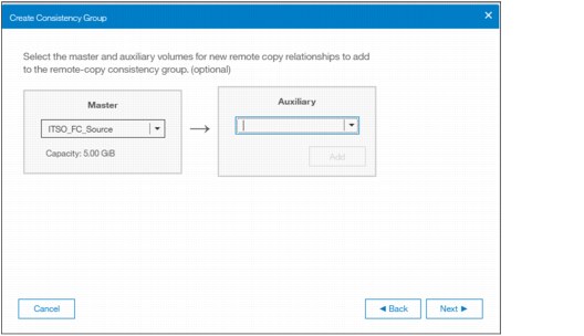
Figure 11-128 Creating new relationships for the new Consistency Group
|
Important: The master and auxiliary Volumes must be of equal size. Therefore, only the targets with the appropriate size are shown in the list for a specific source Volume.
|
7. Specify whether the Volumes in the Consistency Group are synchronized, as shown in Figure 11-120, and click Next.

Figure 11-129 Selecting if Volumes in the new Consistency Group are already synchronized or not
|
Note: If the Volumes are not synchronized, the initial copy will copy the entire source Volume to the remote target Volume. If you suspect Volumes are different or if you have a doubt, then synchronize them to ensure consistency on both sides of the relationship.
|
8. In the last window, select whether you want to start the copy of the Consistency Group or not, as shown in Figure 11-130. Click Finish.

Figure 11-130 Selecting if copy should start or not
11.9.4 Renaming remote copy relationships
To rename one or multiple remote copy relationships, complete these steps:
1. Open the Copy Services Remote Copy pane.

Figure 11-131 Renaming Remote Copy relationships
3. Enter the new name that you want to assign to the relationships and click Rename, as shown in Figure 11-132.

Figure 11-132 Renaming multiple Remote Copy relationships
|
Remote copy relationship name: You can use the letters A - Z and a - z, the numbers 0 - 9, and the underscore (_) character. The remote copy name can be 1 - 15 characters. No blanks are allowed.
|
11.9.5 Renaming a remote copy consistency group
To rename a remote copy consistency group, complete these steps:
1. Open the Copy Services Remote Copy pane.

Figure 11-133 Renaming a Remote Copy Consistency Group
3. Enter the new name that you want to assign to the Consistency Group and click Rename, as shown in Figure 11-134.

Figure 11-134 Entering new name for Consistency Group
|
Remote copy consistency group name: You can use the letters A - Z and a - z, the numbers 0 - 9, and the underscore (_) character. The remote copy name can be 1 - 15 characters. No blanks are allowed.
|
11.9.6 Moving stand-alone remote copy relationships to Consistency Group
To add one or multiple stand-alone relationships to a remote copy consistency group, complete these steps:
1. Open the Copy Services Remote Copy pane.
2. Right-click the relationships to be moved and select Add to Consistency Group, as shown in Figure 11-135.

Figure 11-135 Adding relationships to a Consistency Group
3. Select the Consistency Group for this remote copy relationships by using the menu, as shown in Figure 11-136. Click Add to Consistency Group to confirm your changes.

Figure 11-136 Selecting the Consistency Group to add the relationships to
11.9.7 Removing remote copy relationships from Consistency Group
To remove one or multiple relationships from a remote copy consistency group, complete these steps:
1. Open the Copy Services Remote Copy pane.
2. Right-click the relationships to be removed and select Remove from Consistency Group, as shown in Figure 11-137.

Figure 11-137 Removing relationships from a Consistency Group

Figure 11-138 Confirm the removal of relationships from a Consistency Group
11.9.8 Starting remote copy relationships
When a remote copy relationship is created, the remote copy process can be started. Only relationships that are not members of a Consistency Group, or the only relationship in a Consistency Group, can be started. In any other case, consider starting the Consistency Group instead.
To start one or multiple relationships, complete these steps:
1. Open the Copy Services → Remote Copy pane.

Figure 11-139 Starting remote copy relationships
11.9.9 Starting a remote copy Consistency Group
When a remote copy consistency group is created, the remote copy process can be started for all the relationships that are part of the consistency groups.
To start a consistency group, open the Copy Services Remote Copy pane, right-click the consistency group to be started, and select Start, as shown in Figure 11-140.

Figure 11-140 Starting a remote copy Consistency Group
11.9.10 Switching a relationship copy direction
When a remote copy relationship is in the Consistent synchronized state, the copy direction for the relationship can be changed. Only relationships that are not a member of a Consistency Group, or the only relationship in a Consistency Group, can be switched. In any other case, consider switching the Consistency Group instead.
|
Important: When the copy direction is switched, it is crucial that no outstanding I/O exists to the Volume that changes from primary to secondary because all of the I/O is inhibited to that Volume when it becomes the secondary. Therefore, careful planning is required before you switch the copy direction for a relationship.
|
To switch the direction of a remote copy relationship, complete these steps:
1. Open the Copy Services Remote Copy pane.

Figure 11-141 Switching remote copy relationship direction
3. Because the master-auxiliary relationship direction is reversed, write access is disabled on the new auxiliary Volume (former master Volume), whereas it is enabled on the new master Volume (former auxiliary Volume). A warning message is displayed, as shown in Figure 11-142. Click Yes.

Figure 11-142 Switching master-auxiliary direction of relationships changes the write access
4. When a remote copy relationship is switched, an icon is displayed in the Remote Copy pane list, as shown in Figure 11-143.

Figure 11-143 Switched Remote Copy Relationship
11.9.11 Switching a Consistency Group direction
When a remote copy consistency group is in the Consistent synchronized state, the copy direction for the consistency group can be changed.
|
Important: When the copy direction is switched, it is crucial that no outstanding I/O exists to the Volume that changes from primary to secondary because all of the I/O is inhibited to that Volume when it becomes the secondary. Therefore, careful planning is required before you switch the copy direction for a relationship.
|
To switch the direction of a remote copy consistency group, complete these steps:
1. Open the Copy Services Remote Copy panel.

Figure 11-144 Switching a Consistency Group direction
3. Because the master-auxiliary relationship direction is reversed, write access is disabled on the new auxiliary Volume (former master Volume), while it is enabled on the new master Volume (former auxiliary Volume). A warning message is displayed, as shown in Figure 11-145. Click Yes.

Figure 11-145 Switching direction of Consistency Groups changes the write access
11.9.12 Stopping remote copy relationships
When a remote copy relationship is created and started, the remote copy process can be stopped. Only relationships that are not members of a Consistency Group, or the only relationship in a Consistency Group, can be stopped. In any other case, consider stopping the Consistency Group instead.
To stop one or multiple relationships, complete these steps:
1. Open the Copy Services Remote Copy pane.

Figure 11-146 Stopping a Remote Copy relationship
3. When a remote copy relationship is stopped, access to the auxiliary Volume can be changed so it can be read and written by a host. A confirmation message is displayed as shown in Figure 11-147.

Figure 11-147 Grant access in read and write to the auxiliary Volume
11.9.13 Stopping a Consistency Group
When a remote copy consistency group is created and started, the remote copy process can be stopped.
To stop a consistency group, complete these steps:
1. Open the Copy Services Remote Copy pane.

Figure 11-148 Stopping a Consistency Group
3. When a remote copy consistency group is stopped, access to the auxiliary Volumes can be changed so it can be read and written by a host. A confirmation message is displayed as shown in Figure 11-149.

Figure 11-149 Grant access in read and write to the auxiliary Volumes
11.9.14 Deleting remote copy relationships
To delete remote copy relationships, complete these steps:
1. Open the Copy Services Remote Copy pane.
2. Right-click the relationships that you want to delete and select Delete, as shown in Figure 11-150.

Figure 11-150 Deleting Remote Copy Relationships
3. A confirmation message is displayed, requesting the user to enter the number of relationships to be deleted, as shown in Figure 11-151.

Figure 11-151 Confirmation of relationships deletion
11.9.15 Deleting a Consistency Group
To delete a remote copy consistency group, complete these steps:
1. Open the Copy Services Remote Copy pane.
2. Right-click the consistency group that you want to delete and select Delete, as shown in Figure 11-152.
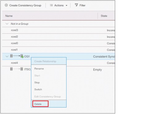
Figure 11-152 Deleting a Consistency Group

Figure 11-153 Confirmation of a Consistency Group deletion
|
Important: Deleting a Consistency Group does not delete its remote copy mappings.
|
11.10 Remote Copy memory allocation
Copy Services features require that small amounts of volume cache be converted from cache memory into bitmap memory to allow the functions to operate, at an I/O group level. If you do not have enough bitmap space allocated when you try to use one of the functions, you will not be able to complete the configuration. The total memory that can be dedicated to these functions is not defined by the physical memory in the system. The memory is constrained by the software functions that use the memory.
For every Remote Copy relationship that is created on a Spectrum Virtualize system, a bitmap table is created to track the copied grains. By default, the system allocates 20 MiB of memory for a minimum of 2 TiB of remote copied source volume capacity. Every 1 MiB of memory provides the following volume capacity for the specified I/O group:
•For 256 KiB grains size, 2 TiB of total Metro Mirror, Global Mirror, or active-active volume capacity.
Review Table 11-14 to calculate the memory requirements and confirm that your system is able to accommodate the total installation size.
Table 11-14 Memory allocation for FlashCopy services
|
Minimum allocated bitmap space
|
Default allocated bitmap space
|
Maximum allocated bitmap space
|
Minimum functionality when using the default values1
|
|
0
|
20 MiB
|
512 MiB
|
40 TiB of remote mirroring volume capacity
|
|
1Remote copy includes Metro Mirror, Global Mirror, and active-active relationships.
|
|||
When you configure change volumes for use with Global Mirror, two internal FlashCopy mappings are created for each change volume.
For Metro Mirror, Global Mirror, and HyperSwap active-active relationships, two bitmaps exist. For Metro Mirror or Global Mirror relationships, one is used for the master clustered system and one is used for the auxiliary system because the direction of the relationship can be reversed. For active-active relationships, which are configured automatically when HyperSwap volumes are created, one bitmap is used for the volume copy on each site because the direction of these relationships can be reversed.
Metro Mirror and Global Mirror relationships do not automatically increase the available bitmap space. You might need to use the chiogrp command to manually increase the space in one or both of the master and auxiliary systems.
11.11 Troubleshooting remote copy
Remote copy (Metro Mirror and Global Mirror) has two primary error codes that are displayed:
•A 1920 error can be considered as a voluntary stop of a relationship by the system when it evaluates the replication will cause errors on the hosts. A 1920 is a congestion error. This error means that the source, the link between the source and target, or the target cannot keep up with the requested copy rate. The system then triggers a 1920 error to prevent replication from having undesired effects on hosts.
•A 1720 error is a heartbeat or system partnership communication error. This error often is more serious because failing communication between your system partners involves extended diagnostic time.
11.11.1 1920 error
A 1920 error is deliberately generated by the system and should be considered as a control mechanism. It occurs after 985003 (“Unable to find path to disk in the remote cluster (system) within the time-out period”) or 985004 (“Maximum replication delay has been exceeded”) events.
It can have several triggers, including the following probable causes:
•Primary system or SAN fabric problem (10%)
•Primary system or SAN fabric configuration (10%)
•Secondary system or SAN fabric problem (15%)
•Secondary system or SAN fabric configuration (25%)
•Intercluster link problem (15%)
•Intercluster link configuration (25%)
In practice, the most often overlooked cause is latency. Global Mirror has a round-trip-time tolerance limit of 80 or 250 milliseconds, depending on the firmware version and the hardware model. A message that is sent from the source IBM Spectrum Virtualize system to the target system and the accompanying acknowledgment must have a total time of 80 or 250 milliseconds round trip. In other words, it must have up to 40 or 125 milliseconds latency each way.
The primary component of your round-trip time is the physical distance between sites. For every 1000 kilometers (621.4 miles), you observe a 5-millisecond delay each way. This delay does not include the time that is added by equipment in the path. Every device adds a varying amount of time, depending on the device, but a good rule is 25 microseconds for pure hardware devices.
For software-based functions (such as compression that is implemented in applications), the added delay tends to be much higher (usually in the millisecond plus range.) The following is an example of a physical delay.
Company A has a production site that is 1900 kilometers (1180.6 miles) away from its recovery site. The network service provider uses a total of five devices to connect the two sites. In addition to those devices, Company A employs a SAN FC router at each site to provide FCIP to encapsulate the FC traffic between sites.
Now, there are seven devices, and 1900 kilometers (1180.6 miles) of distance delay. All the devices are adding 200 microseconds of delay each way. The distance adds 9.5 milliseconds each way, for a total of 19 milliseconds. Combined with the device latency, the delay is 19.4 milliseconds of physical latency minimum, which is under the 80-millisecond limit of Global Mirror until you realize that this number is the best case number.
The link quality and bandwidth play a large role. Your network provider likely ensures a latency maximum on your network link. Therefore, be sure to stay as far beneath the Global Mirror round-trip-time (RTT) limit as possible. You can easily double or triple the expected physical latency with a lower quality or lower bandwidth network link. Then, you are within the range of exceeding the limit if high I/O occurs that exceeds the existing bandwidth capacity.
When you get a 1920 event, always check the latency first. The FCIP routing layer can introduce latency if it is not properly configured. If your network provider reports a much lower latency, you might have a problem at your FCIP routing layer. Most FCIP routing devices have built-in tools to enable you to check the RTT. When you are checking latency, remember that TCP/IP routing devices (including FCIP routers) report RTT by using standard 64-byte ping packets.
In Figure 11-154, you can see why the effective transit time must be measured only by using packets that are large enough to hold an FC frame, or 2148 bytes (2112 bytes of payload and 36 bytes of header). Allow estimated resource requirements to be a safe amount because various switch vendors have optional features that might increase this size. After you verify your latency by using the proper packet size, proceed with normal hardware troubleshooting.
Before proceeding, look at the second largest component of your RTT, which is serialization delay. Serialization delay is the amount of time that is required to move a packet of data of a specific size across a network link of a certain bandwidth. The required time to move a specific amount of data decreases as the data transmission rate increases.
Figure 11-154 shows the orders of magnitude of difference between the link bandwidths. It is easy to see how 1920 errors can arise when your bandwidth is insufficient. Never use a TCP/IP ping to measure RTT for FCIP traffic.

Figure 11-154 Effect of packet size (in bytes) versus the link size
In Figure 11-154, the amount of time in microseconds that is required to transmit a packet across network links of varying bandwidth capacity is compared. The following packet sizes are used:
•64 bytes: The size of the common ping packet
•1500 bytes: The size of the standard TCP/IP packet
•2148 bytes: The size of an FC frame
Finally, your path maximum transmission unit (MTU) affects the delay that is incurred to get a packet from one location to another location. An MTU might cause fragmentation or be too large and cause too many retransmits when a packet is lost.
|
Note: Unlike 1720 errors, 1920 errors are deliberately generated by the system because it evaluated that a relationship could impact the host’s response time. The system has no indication on if/when the relationship can be restarted. Therefore, the relationship cannot be restarted automatically and it needs to be done manually.
|
11.11.2 1720 error
The 1720 error (event ID 050020) is the other problem remote copy might encounter. The amount of bandwidth that is needed for system-to-system communications varies based on the number of nodes. It is important that it is not zero. When a partner on either side stops communication, a 1720 is displayed in your error log. According to the product documentation, there are no likely field-replaceable unit breakages or other causes.
The source of this error is most often a fabric problem or a problem in the network path between your partners. When you receive this error, check your fabric configuration for zoning of more than one host bus adapter (HBA) port for each node per I/O Group if your fabric has more than 64 HBA ports zoned. The suggested zoning configuration for fabrics is one port for each node per I/O Group per fabric that is associated with the host.
For those fabrics with 64 or more host ports, this suggestion becomes a rule. Therefore, you see four paths to each Volume discovered on the host because each host needs to have at least two FC ports from separate HBA cards, each in a separate fabric. On each fabric, each host FC port is zoned to two Storwize node ports where each node port comes from a different Storwize node. This configuration provides four paths per Volume. More than four paths per Volume are supported but not recommended.
Improper zoning can lead to SAN congestion, which can inhibit remote link communication intermittently. Checking the zero buffer credit timer with IBM Spectrum Control and comparing against your sample interval reveals potential SAN congestion. If a zero buffer credit timer is more than 2% of the total time of the sample interval, it might cause problems.
Next, always ask your network provider to check the status of the link. If the link is acceptable, watch for repeats of this error. It is possible in a normal and functional network setup to have occasional 1720 errors, but multiple occurrences could indicate a larger problem.
If you receive multiple 1720 errors, recheck your network connection and then check the system partnership information to verify its status and settings. Then, perform diagnostics for every piece of equipment in the path between the two Storwize systems. It often helps to have a diagram that shows the path of your replication from both logical and physical configuration viewpoints.
|
Note: With Consistency Protection enabled on the MM/GM relationships, the system tries to resume the replication when possible. Therefore, it is not necessary to manually restart the failed relationship after a 1720 error is triggered.
|
If your investigations fail to resolve your remote copy problems, contact your IBM Support representative for a more complete analysis.
..................Content has been hidden....................
You can't read the all page of ebook, please click here login for view all page.