


Graphical user interface
This chapter describes an overview of the IBM Spectrum Virtualize graphical user interface (GUI). The management GUI is a tool enabled and provided by IBM Spectrum Virtualize that helps you to monitor, manage, and configure your system.
This chapter explains the basic view and the configuration procedures that are required to get your IBM Storwize V7000 environment running as quickly as possible by using the GUI.
This chapter does not describe advanced troubleshooting or problem determination and some of the complex operations (compression, encryption) because they are explained later in this book.
This chapter includes the following topics:
•Access to GUI
Throughout the chapter, all GUI menu items are introduced in a systematic, logical order as they appear in the GUI. However, topics that are described more in detail in other chapters of the book are only referred to here. For example, Pools, Volumes, Hosts, Copy Services are described in dedicated chapters including their associated GUI operations.
|
Demonstration: The IBM Client Demonstration Center has a demo of the V8.1 GUI here:
|
5.1 Normal operations using the GUI
This section describes useful tasks using the GUI that help administrators to manage, monitor, and configure the IBM Storwize V7000 as quickly as possible. As an example, we configured the IBM Storwize V7000 in a standard topology.
As mentioned, the GUI is a built-in software component within the IBM Spectrum Virtualize software.
Multiple users can be logged in to the GUI at any time. However, no locking mechanism exists, so be aware that if two users change the same object at the same time, the last action that is entered from the GUI is the one that takes effect.
IBM Spectrum Virtualize V8.1 introduced a major change in the GUI design to be aligned with the unified look and visual style of other IBM products. Also, some specific features and options to manage IBM Storwize V7000 have been added and some limited in their variability of attributes. This chapter highlights these additions and limitations as compared to the previous version of V7.8.
|
Important: Data entries that are made through the GUI are case-sensitive.
You must enable Java Script in your browser. For Mozilla Firefox, Java Script is enabled by default and requires no additional configuration. Follow the instructions at:
|
5.1.1 Access to GUI
To access the IBM Storwize V7000 GUI, type the IP address that was set during the initial setup process into the address line of your web browser. You can connect from any workstation that can communicate with the system. The login window opens (Figure 5-1).
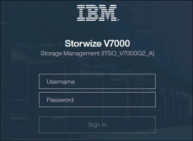
Figure 5-1 Login window of Storwize V7000
It is very preferable for each user to have their own unique account. The default user accounts should be disabled for use or their passwords changed and kept secured for emergency purposes only. This approach helps to identify personnel working on the systems and track all important changes done by them. The Superuser account should be used for initial configuration only.
After a successful login, the V8.1 welcome window shows up with the new system dashboard (Figure 5-2).
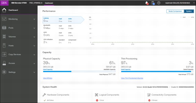
Figure 5-2 Welcome page with new dashboard
The Dashboard is divided into three sections:
•Performance provides important information about latency, bandwidth, IOPS, and CPU utilization. All of this information can be viewed either at system level or canister level. A Node comparison view shows the differences in characteristics of each node (Figure 5-3). The performance graph is updated with new data every 5 seconds.

Figure 5-3 Performance statistics
•Capacity section shows the current utilization of attached storage and its usage. Apart from physical capacity, it also shows compressed and thin-provisioned storage (Figure 5-4).
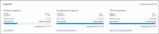
Figure 5-4 Capacity overview
•System Health indicates the current status of all critical system components grouped in three categories: Hardware, logical, and connectivity components. From each group, you can navigate directly to the section of GUI where the affected component is managed from (Figure 5-5).
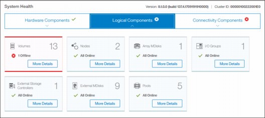
Figure 5-5 System health overview
The Dashboard in V8.1 appears as a welcome page instead of system pane as in previous versions. This System overview has been relocated to the menu Monitoring → System. Although the Dashboard pane provides key information about system behavior, the System menu is a preferred starting point to obtain necessary details about your Storwize V7000 components. This advice is followed in the next sections of this chapter.
5.2 Introduction to the GUI
As shown in Figure 5-6, the former IBM Storwize V7000 GUI System pane has been relocated to Monitoring → System.

Figure 5-6 IBM Storwize V7000 GUI
5.2.1 Task menu
The IBM Spectrum Virtualize GUI task menu is always available on the left side of the GUI window. To browse by using this menu, click the action and choose a task that you want to display, as shown in Figure 5-7.

Figure 5-7 The task menu
By reducing the horizontal size of your browser window, the wide task menu shrinks to the icons only.
5.2.2 Suggested tasks
After an initial configuration, IBM Spectrum Virtualize shows the information about suggested tasks notifying the administrator that several key IBM Storwize V7000 functions are not yet configured. If necessary, this indicator can be closed and these tasks can be performed at any time. Figure 5-8 shows the suggested tasks in the System pane.
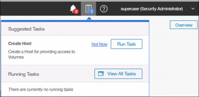
Figure 5-8 Suggested tasks
In this case, the GUI warns you that no host is defined yet. You can directly perform the task from this window or cancel it and run the procedure later at any convenient time. Other suggested tasks that typically appear after the initial system configuration are to create a volume and configure a storage pool.
The dynamic IBM Spectrum Virtualize menu contains the following panes:
•Dashboard
•Monitoring
•Pools
•Volumes
•Hosts
•Copy Services
•Access
•Settings
5.2.3 Notification icons and help
Two notification icons are located in the top navigation area of the GUI (Figure 5-9). The left icon indicates warning and error alerts recorded in the event log, whereas the middle icon shows running jobs and suggested tasks. The third most right icon offers a help menu with content associated with the current tasks and the currently opened GUI menu.
Figure 5-9 Notification area
Alerts indication
The left icon in the notification area informs administrators about important alerts in the systems. Click the icon to list warning messages in yellow and errors in red (Figure 5-10).
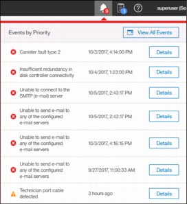
Figure 5-10 System alerts
You can navigate directly to the events menu by clicking View All Events option or see each event message separately by clicking the Details icon of the specific message, analyze the content, and eventually run suggested fix procedure (Figure 5-11).

Figure 5-11 External storage connectivity loss
Running jobs and suggested tasks
The middle icon in the notification area provides an overview of currently running tasks triggered by administrator and the suggested tasks recommending users to perform specific configuration actions.
In our case shown in Figure 5-12, we have not yet defined any hosts attached to the systems. Therefore, the system suggests that we do so and offers us direct access to the associated host menu. Click Run Task to define the host according to the procedure explained in Chapter 8, “Hosts” on page 317. If you do not want to define any host at the moment, click Not Now and the suggestion message disappears.

Figure 5-12 Storage allocation area
Similarly, you can analyze the details of running tasks, either all of them together in one window or of a single task. Click View to open the volume format job as shown in Figure 5-13.

Figure 5-13 Details of running task
The following information can be displayed as part of running tasks:
•Volume migration
•Managed disk (MDisk) removal
•Image mode migration
•Extent migration
•IBM FlashCopy
•Metro Mirror and Global Mirror
•Volume formatting
•Space-efficient copy repair
•Volume copy verification and synchronization
•Estimated time for the task completion
Help
To access online help, click the question mark icon in the left of the notification area and select the context-based help topic, as shown in Figure 5-14. The help window displays the context item for the pane that you are working on.
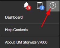
Figure 5-14 Access help menu
For example, on the Dashboard pane, you have the option to open help related to the dashboard-provided information as shown in Figure 5-15.

Figure 5-15 Example of Dashboard help content
The Help Contents option redirects you to the SVC IBM Knowledge Center. However, it requires internet access from the workstation where the management GUI is started.
5.3 Overview window
Starting with IBM Spectrum Virtualize release V7.4, the welcome window of the GUI changed from the well-known former Overview pane to the new System pane. In V8.1, the welcome window has been altered to the Dashboard and the Overview roll-down pane is available from Monitoring → System. Clicking Overview in the upper-right corner of the System pane opens the Overview pane with options that are similar to previous versions of the software. See Figure 5-16 for details.
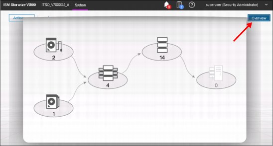
Figure 5-16 Opening the Overview pane
The following content of the chapter helps you to understand the structure of the pane and how to navigate to various system components to manage them more efficiently and quickly.
5.3.1 Content-based organization
The following sections describe several view options within the GUI in which you can filter (to minimize the amount of data that is shown on the window), sort, and reorganize the content of the window.
Table filtering
On most pages, a Filter option (magnifying glass icon) is available on the upper-left side of the window. Use this option if the list of object entries is too long.
Complete the following steps to use search filtering:
1. Click Filter on the upper-left side of the window, as shown in Figure 5-17, to open the search box.
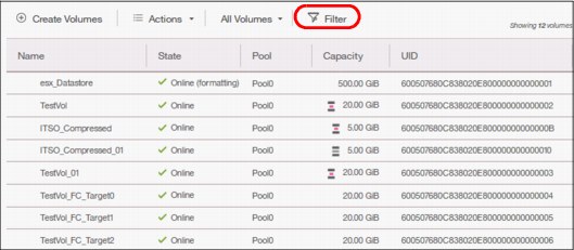
Figure 5-17 Show filter search box
2. Enter the text string that you want to filter and press Enter.
3. By using this function, you can filter your table that is based on column names. In our example, a volume list is displayed that contains the names that include DS somewhere in the name. DS is highlighted in amber, as shown in Figure 5-18. The search option is not case-sensitive.

Figure 5-18 Show filtered rows

Figure 5-19 Reset filter
|
Filtering: This filtering option is available in most menu options of the GUI.
|
Table information
In the table view, you can add or remove the information in the tables on most pages.
For example, on the Volumes pane, complete the following steps to add a column to the table:
1. Right-click any column headers of the table or select the icon in the left corner of the table header. A list of all of the available columns displays, as shown in Figure 5-20.
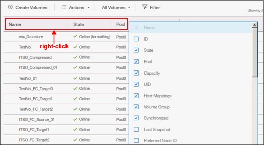
Figure 5-20 Add or remove details in a table
2. Select the column that you want to add (or remove) from this table. In our example, we added the volume ID column and sorted the content by ID, as shown on the left in Figure 5-21.
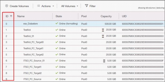
Figure 5-21 Table with an added ID column
3. You can repeat this process several times to create custom tables to meet your requirements.
4. You can always return to the default table view by selecting Restore Default View in the column selection menu, as shown in Figure 5-22.

Figure 5-22 Restore default table view
|
Sorting: By clicking a column, you can sort a table based on that column in ascending or descending order.
|
Shifting columns in tables
You can move columns by left-clicking and moving the column right or left, as shown in Figure 5-23. We are attempting to move the Capacity column before the Pool column.
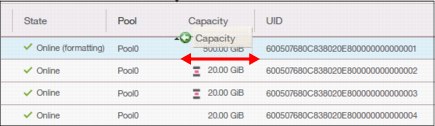
Figure 5-23 Reorganizing table columns
5.4 Monitoring menu
Click the Monitoring icon in left pane to open the Monitoring menu (Figure 5-24 on page 148). The Monitoring menu offers these navigation options:
•System: This option opens the general overview of the IBM Storwize V7000 system, including the depiction of all devices in a system. For more information, see 5.4.1, “System overview” on page 148.
•Events: This option tracks all informational, warning, and error messages that occurred in the system. You can apply various filters to sort the messages according to your needs or export the messages to an external comma-separated values (CSV) file. For more information, see 5.4.2, “Events” on page 150.
•Performance: This option reports the general system statistics that relate to the processor (CPU) utilization, host and internal interfaces, volumes, and MDisks. The GUI allows you to switch between megabytes per second (MBps) or IOPS. For more information, see 5.4.3, “Performance” on page 151.
•Background Tasks: The option shows the progress of all tasks running in the background as listed in “Running jobs and suggested tasks” on page 142
The following section describes each option on the Monitoring menu (Figure 5-24).

Figure 5-24 Monitoring menu
5.4.1 System overview
The System option on the Monitoring menu provides a general overview about the IBM Storwize V7000, including the depiction of all devices that are part of the system (Figure 5-25).
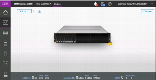
Figure 5-25 System overview that shows capacity
When you click a specific component of the node canister, a pop-up window indicates the details of the component, such as the disk drives in the unit.
By right-clicking and selecting Properties, you see detailed technical parameters, such as ID, state (online or offline), drive capacity, and the drive use as shown in Figure 5-26.

Figure 5-26 Drive information
In an environment with multiple IBM Storwize V7000 clusters, you can easily direct the onsite personnel or technician to the correct device by enabling the identification LED on the front pane. Click Identify in the menu that is shown in Figure 5-27.
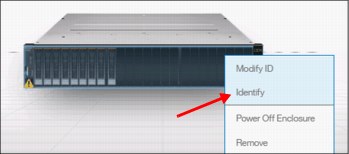
Figure 5-27 Identification LED
Wait for confirmation from the technician that the device in the data center was correctly identified.
After the confirmation, click Turn LED Off (Figure 5-28).
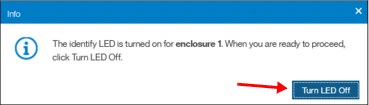
Figure 5-28 Using the identification LED
Alternatively, you can use the command-line interface (CLI) to get the same results. Type the following commands in this sequence:
1. Type svctask chenclosure -identify yes 1 (or just type chenclosure -identify yes 1).
2. Type svctask chenclosure -identify no 1 (or just type chenclosure -identify no 1).
Each system that is shown in the System view pane can be rotated by 180° to see its rear side. Click the rotation arrow in the lower-right corner of the device, as illustrated in Figure 5-29.
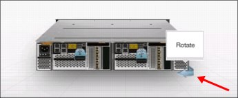
Figure 5-29 Rotating the enclosure
5.4.2 Events
The Events option, available in the Monitoring menu, tracks all informational, warning, and error messages that occur in the system. You can apply various filters to sort them, or export them to an external CSV file. A CSV file can be created from the information that is shown here. Figure 5-30 provides an example of records in the system Event log.
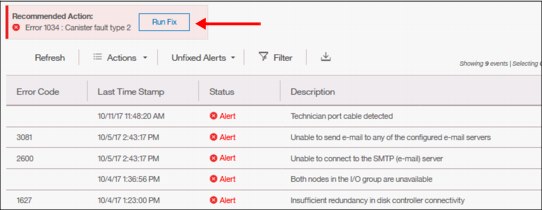
Figure 5-30 Event log list
For the error messages with the highest internal priority, perform corrective actions by running fix procedures. Click the Run Fix button as shown in Figure 5-30 on page 150. The fix procedure wizard opens as indicated in Figure 5-31.
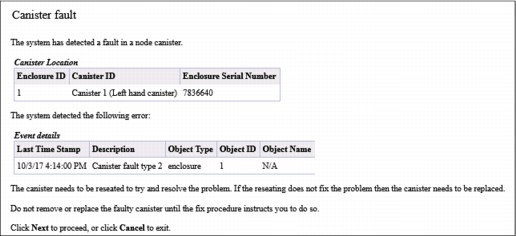
Figure 5-31 Performing fix procedures
The wizard guides you through the troubleshooting and fixing process either from a hardware or software perspective. If you consider that the problem cannot be fixed without a technician’s intervention, you can cancel the procedure execution at any time. Details about fix procedures are discussed in Chapter 13, “RAS, monitoring, and troubleshooting” on page 663.
5.4.3 Performance
The Performance pane reports the general system statistics that relate to processor (CPU) utilization, host and internal interfaces, volumes, and MDisks. You can switch between MBps or IOPS, and drill down in the statistics to the node level. This capability might be useful when you compare the performance of each control canister in the system if problems exist after a node failover occurs. See Figure 5-32.

Figure 5-32 Performance statistics of the IBM Storwize V7000
The performance statistics in the GUI show, by default, the latest 5 minutes of data. To see details of each sample, click the graph and select the time stamp, as shown in Figure 5-33.
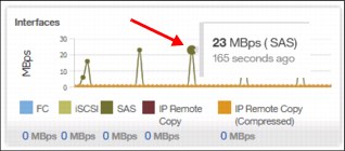
Figure 5-33 Sample details
The charts that are shown in Figure 5-33 represent 5 minutes of the data stream. For in-depth storage monitoring and performance statistics with historical data about your IBM Storwize system, use IBM Spectrum Control (formerly enabled by IBM Tivoli Storage Productivity Center for Disk and IBM Virtual Storage Center).
5.4.4 Background tasks
This menu provides an overview of currently running tasks triggered by the administrator. In contrast to the Running jobs and Suggested tasks indication in the middle of top pane, it does not list the suggested tasks that administrators should consider performing. The overview provides more details than the indicator itself as shown in Figure 5-34.
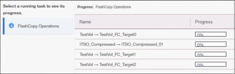
Figure 5-34 List of running tasks
You can switch between each type (group) of operation, but you cannot show them all in one list (Figure 5-35).
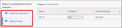
Figure 5-35 Switching between types of background tasks
5.5 Pools
Pools menu option is used to configure and manage storage pools, internal, and external storage, MDisks, and to migrate old attached storage to the system.
Pools menu contains the following items accessible from GUI (Figure 5-36):
•Pools
•Volumes by Pool
•Internal Storage
•External Storage
•MDisks by Pool
•System Migration

Figure 5-36 Pools menu
The details about storage pool configuration and management are provided in Chapter 6, “Storage pools” on page 185.
5.6 Volumes
A volume is a logical disk that the system presents to attached hosts. Using GUI operations, you can create different types of volumes, depending on the type of topology that is configured on your system.
Volumes menu contains the following items (Figure 5-37 on page 154):
•Volumes
•Volumes by Pool
•Volumes by Host
•Cloud Volumes

Figure 5-37 Volumes menu
The details about all those tasks and guidance through the configuration and management process are provided in Chapter 7, “Volumes” on page 239.
5.7 Hosts
A host system is a computer that is connected to the system through either a Fibre Channel interface or an IP network. It is a logical object that represents a list of worldwide port names (WWPNs) that identify the interfaces that the host uses to communicate with Storwize V7000. Both Fibre Channel and SAS connections use WWPNs to identify the host interfaces to the systems.
Hosts menu consists of the following choices (Figure 5-38):
•Hosts
•Host Clusters
•Ports by Host
•Mappings
•Volumes by Host
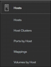
Figure 5-38 Hosts menu
Additional detailed information about configuration and management of hosts using the GUI is available in Chapter 8, “Hosts” on page 317.
5.8 Copy Services
The IBM Spectrum Virtualize copy services and volumes copy operations are based on the IBM FlashCopy function. In its basic mode, the function creates copies of content on a source volume to a target volume. Any data that existed on the target volume is lost and is replaced by the copied data.
More advanced functions allow FlashCopy operations to occur on multiple source and target volumes. Management operations are coordinated to provide a common, single point-in-time for copying target volumes from their respective source volumes. This technique creates a consistent copy of data that spans multiple volumes.
The IBM SAN Volume Controller Copy Services menu offers the following operations in the GUI (Figure 5-39):
•FlashCopy
•Consistency Groups
•FlashCopy Mappings
•Remote Copy
•Partnership

Figure 5-39 Copy Services in GUI
Because the Copy Services are one of the most important features for resiliency solutions, study the additional technical details in Chapter 11, “Advanced Copy Services” on page 437.
5.9 Access
The access menu in the GUI maintains who can login to the system, defines the access rights to the user, and tracks what has been done by each privileged user to the system. It is logically split into two categories:
•Users
•Audit Log
This explains how to create, modify, or remove user, and how to see records in the audit log.
The Access menu is available from the left pane as shown in Figure 5-40.

Figure 5-40 Access menu
5.9.1 Users
You can create local users who can access the system. These user types are defined based on the administrative privileges that they have on the system.
Local users must provide either a password, a Secure Shell (SSH) key, or both. Local users are authenticated through the authentication methods that are configured on the system. If the local user needs access to the management GUI, a password is needed for the user. If the user requires access to the CLI through SSH, either a password or a valid SSH key file is necessary. Local users must be part of a user group that is defined on the system. User groups define roles that authorize the users within that group to a specific set of operations on the system.

Figure 5-41 Defining User Group in Storwize V7000
The following privilege User group roles exist in the IBM Spectrum Virtualize:
•Security Administrator can manage all functions of the systems except tasks associated with commands satask and sainfo.
•Administrator has full rights in the system except those commands related to user management and authentication.
•Restricted Administrator has the same rights as Administrators except removing volumes, host mappings, hosts, or pools. This is the ideal option for support personnel.
•Copy Operators can start, stop, or pause any FlashCopy-based operations.
•Monitor users have access to all viewing operations. They cannot change any value or parameters of the system.
•Service users can set the time and date on the system, delete dump files, add and delete nodes, apply service, and shut down the system. They have access to all views.
•VASA Provider users can manage VMware vSphere Virtual Volumes (VVOLs).
Registering new user
After you have defined your group, in our example MyGroup with Administrators privileges, you can now register a new user within this group. Click Create User and select MyGroup. See the details in Figure 5-42.
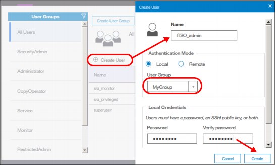
Figure 5-42 Registering new user account
Deleting a user
To remove a user account, select the user in the same menu, click Actions, and select Delete (Figure 5-43).
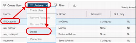
Figure 5-43 Deleting user account
|
Attention: When you click Delete, the user account is directly deleted from SVC. There is no additional confirmation request.
|
Resetting user password
To set a new password for the user, right-click the user (or use the Actions button) and select Properties. In this window, you can either assign the user to a different group or reset their password (Figure 5-44).
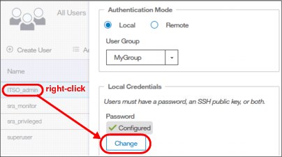
Figure 5-44 Changing user’s password
5.9.2 Audit log
An audit log documents actions that are submitted through the management GUI or the command-line interface. You can use the audit log to monitor user activity on your system.
The audit log entries provide the following information:
•Time and date when the action or command was submitted
•Name of the user who completed the action or command
•IP address of the system where the action or command was submitted
•Name of source and target node on which the command was submitted
•Parameters that were submitted with the command, excluding confidential information
•Results of the command or action that completed successfully
•Sequence number and the object identifier that is associated with the command or action
An example of the audit log is shown in Figure 5-45.
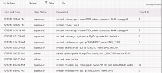
Figure 5-45 Audit log
|
Important: Failed commands are not recorded in the audit log. Commands triggered by IBM support personnel are recorded with the flag Challenge because they use challenge-response authentication.
|
5.10 Settings
Use the Settings pane to configure system options for notifications, security, IP addresses, and preferences that are related to display options in the management GUI (Figure 5-46).
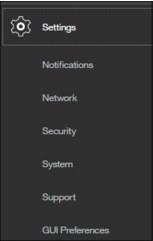
Figure 5-46 Settings menu
The following options are available for configuration from the Settings menu:
•Notifications: The system can use Simple Network Management Protocol (SNMP) traps, syslog messages, and Call Home emails to notify you and the support center when significant events are detected. Any combination of these notification methods can be used simultaneously.
•Network: Use the Network pane to manage the management IP addresses for the system, service IP addresses for the nodes, and iSCSI and Fibre Channel configurations. The system must support Fibre Channel or Fibre Channel over Ethernet connections to your storage area network (SAN).
•Security: Use the Security pane to configure and manage remote authentication services.
•System: Navigate to the System menu item to manage overall system configuration options, such as licenses, updates, and date and time settings.
•Support: Helps to configure and manage connections, and upload support packages to the support center.
•GUI Preferences: Configure welcome message after login, refresh internals and GUI logout timeouts.
These options are described in more detail in the following sections.
5.10.1 Notifications menu
IBM Storwize V7000 can use SNMP traps, syslog messages, and Call Home email to notify you and the IBM Support Center when significant events are detected. Any combination of these notification methods can be used simultaneously.
Notifications are normally sent immediately after an event is raised. However, events can occur because of service actions that are performed. If a recommended service action is active, notifications about these events are sent only if the events are still unfixed when the service action completes.
Email notifications
The Call Home feature transmits operational and event-related data to you and IBM through a Simple Mail Transfer Protocol (SMTP) server connection in the form of an event notification email. When configured, this function alerts IBM service personnel about hardware failures and potentially serious configuration or environmental issues.
Complete the following steps to view email event notifications:
1. From the main System pane, move the mouse pointer over the Settings selection in the dynamic menu and click Notifications, as shown in Figure 5-47.

Figure 5-47 Selecting Notifications in the Settings section

Figure 5-48 Viewing call home event information
3. This view provides the following useful information about email notification and call-home information, among others:
– The IP of the email server (SMTP Server) and Port
– The Call-home email address
– The email of one or more users set to receive any email notifications
– The contact information of the person in the organization responsible for the system
– System location
SNMP notifications
SNMP is a standard protocol for managing networks and exchanging messages. The system can send SNMP messages that notify personnel about an event. You can use an SNMP manager to view the SNMP messages that are sent by IBM Storwize V7000.
To view the SNMP configuration, use the System window. Move the mouse pointer over the Settings icon and click Notification → SNMP (Figure 5-49).

Figure 5-49 Setting SNMP server and traps
From this window (Figure 5-49), you can view and configure an SNMP server to receive various informational, error, or warning notifications by setting the following information:
•IP Address
The address for the SNMP server.
•Server Port
The remote port number for the SNMP server. The remote port number must be a value of 1 - 65535.
•Community
The SNMP community is the name of the group to which devices and management stations that run SNMP belong.
•Event Notifications
Consider the following points about event notifications:
– Select Error if you want the user to receive messages about problems, such as hardware failures, that must be resolved immediately.
|
Important: Browse to Recommended Actions to run the fix procedures on these notifications.
|
– Select Warning if you want the user to receive messages about problems and unexpected conditions. Investigate the cause immediately to determine any corrective action.
|
Important: Browse to Recommended Actions to run the fix procedures on these notifications.
|
– Select Info if you want the user to receive messages about expected events. No action is required for these events.
To remove an SNMP server, click the Minus sign (-). To add another SNMP server, click the Plus sign (+).
Syslog notifications
The syslog protocol is a standard protocol for forwarding log messages from a sender to a receiver on an IP network. The IP network can be IPv4 or IPv6. The system can send syslog messages that notify personnel about an event. You can use the Syslog pane to view the Syslog messages that are sent by the IBM Storwize V7000. To view the Syslog configuration, use the System pane and move the mouse pointer over Settings and click Notification → Syslog (Figure 5-50).

Figure 5-50 Setting Syslog messages
From this window, you can view and configure a syslog server to receive log messages from various systems and store them in a central repository by entering the following information:
•IP Address
The IP address for the syslog server.
•Facility
The facility determines the format for the syslog messages. The facility can be used to determine the source of the message.
•Message Format
The message format depends on the facility. The system can transmit syslog messages in the following formats:
– The concise message format provides standard detail about the event.
– The expanded format provides more details about the event.
•Event Notifications
Consider the following points about event notifications:
– Select Error if you want the user to receive messages about problems, such as hardware failures, that must be resolved immediately.
|
Important: Browse to Recommended Actions to run the fix procedures on these notifications.
|
– Select Warning if you want the user to receive messages about problems and unexpected conditions. Investigate the cause immediately to determine whether any corrective action is necessary.
|
Important: Browse to Recommended Actions to run the fix procedures on these notifications.
|
– Select Info if you want the user to receive messages about expected events. No action is required for these events.
To remove a syslog server, click the Minus sign (-). To add another syslog server, click the Plus sign (+).
The syslog messages can be sent in concise message format or expanded message format.
Example 5-1 shows a compact format syslog message.
Example 5-1 Compact syslog message example
IBM2145 #NotificationType=Error #ErrorID=077001 #ErrorCode=1070 #Description=Node
CPU fan failed #ClusterName=SVCCluster1 #Timestamp=Wed Oct 02 08:00:00 2017 BST
#ObjectType=Node #ObjectName=Node1 #CopyID=0 #ErrorSequenceNumber=100
Example 5-2 shows an expanded format syslog message.
Example 5-2 Full format syslog message example
IBM2145 #NotificationType=Error #ErrorID=077001 #ErrorCode=1070 #Description=Node
CPU fan failed #ClusterName=SVCCluster1 #Timestamp=Wed Oct 02 08:00:00 2017 BST
#ObjectType=Node #ObjectName=Node1 #CopyID=0 #ErrorSequenceNumber=100 #ObjectID=2
#NodeID=2 #MachineType=2076524#SerialNumber=1234567 #SoftwareVersion=8.1.0.0
(build 137.4.1709291021000)#FRU=fan 24P1118, system board 24P1234 #AdditionalData(0->63)=0000000021000000000000000000000000000000000000000000000000000000000000000000000000000000000000000000000000000000000000000000000000#AdditionalData(64-127)=00000000000000000000000000000000000000000000000000000000000000000000000000000000000000000000000000000000000000000000000000000000
5.10.2 Network
This section describes how to view the network properties of the IBM Storwize V7000 system. The network information can be obtained by choosing Network as shown in Figure 5-51.
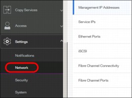
Figure 5-51 Accessing network information
Configuring the network
The procedure to set up and configure IBM Storwize V7000 network interfaces is described in Chapter 4, “Initial configuration” on page 85.
Management IP addresses
To view the management IP addresses of the IBM Spectrum Virtualize, select Settings → Network, and click Management IP Addresses. The GUI shows the management IP address by moving the mouse cursor over the network ports as shown Figure 5-52.
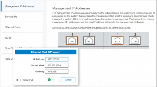
Figure 5-52 Viewing the management IP addresses
Service IP information
To view the Service IP information of your IBM Spectrum Virtualize, select Settings → Network as shown in Figure 5-51 on page 164, and click the Service IP Address option to view the properties as shown in Figure 5-53.
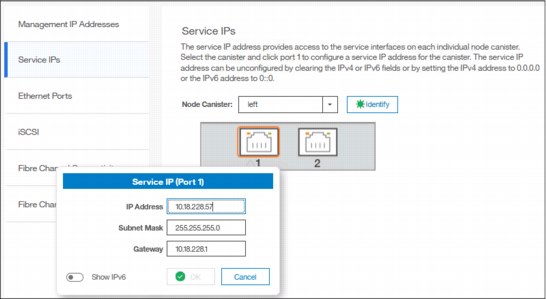
Figure 5-53 Viewing service IP address
The service IP address is commonly used to provide access to the network interfaces on each individual node of the control enclosure.
Instead of reaching the Management IP address, the service IP address directly connects to each individual node canister for service operations. You can select a node canister of the control enclosure from the drop-down list and then click any of the ports that are shown in the GUI. The service IP address can be configure to support IPv4 or IPv6.
iSCSI information
From the iSCSI pane in the Settings menu, you can display and configure parameters for the system to connect to iSCSI-attached hosts, as shown in Figure 5-54.
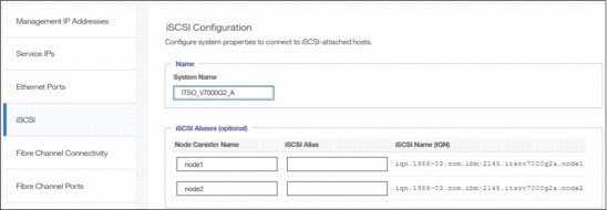
Figure 5-54 iSCSI Configuration
The following parameters can be updated:
•System Name
It is important to set the system name correctly because it is part of the IQN for the node.
|
Important: If you change the name of the system after iSCSI is configured, you might need to reconfigure the iSCSI hosts.
|
To change the system name, click the system name and specify the new name.
|
System name: You can use the letters A - Z and a - z, the numbers 0 - 9, and the underscore (_) character. The name can be 1 - 63 characters.
|
•iSCSI Aliases (Optional)
An iSCSI alias is a user-defined name that identifies the node to the host. Complete the following steps to change an iSCSI alias:
a. Click an iSCSI alias.
b. Specify a name for it.
Each node has a unique iSCSI name that is associated with two IP addresses. After the host starts the iSCSI connection to a target node, this IQN from the target node is visible in the iSCSI configuration tool on the host.
•iSNS and CHAP
You can specify the IP address for the iSCSI Storage Name Service (iSNS). Host systems use the iSNS server to manage iSCSI targets and for iSCSI discovery.
You can also enable Challenge Handshake Authentication Protocol (CHAP) to authenticate the system and iSCSI-attached hosts with the specified shared secret.
The CHAP secret is the authentication method that is used to restrict access for other iSCSI hosts that use the same connection. You can set the CHAP for the whole system under the system properties or for each host definition. The CHAP must be identical on the server and the system/host definition. You can create an iSCSI host definition without the use of a CHAP.
Fibre Channel information
As shown in Figure 5-55, you can use the Fibre Channel Connectivity pane to display the FC connectivity between nodes and other storage systems and hosts that attach through the FC network. You can filter by selecting one of the following fields:
•All nodes, storage systems, and hosts
•Systems
•Nodes
•Storage systems
•Hosts
View the Fibre Channel Connectivity, as shown in Figure 5-55.
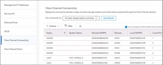
Figure 5-55 Fibre Channel connections
In the Fibre Channel Ports pane, you can use this view to display how the Fibre Channel port is configured across all control node canisters in the system. This view helps, for example, to determine with which other clusters the port is allowed to communicate (Figure 5-56).
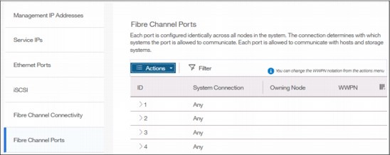
Figure 5-56 Viewing Fibre Channel Port properties
5.10.3 System menu
Use the System option from the Settings menu to view and change the time and date settings, work with licensing options, download configuration settings, work with VMware VVOLs and IP Quorum, or download software upgrade packages.
Date and time
Complete the following steps to view or configure the date and time settings:
1. From the main System pane, move the pointer over Settings and click System.
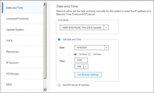
Figure 5-57 Date and Time window
3. From this pane, you can modify the following information:
– Time zone
Select a time zone for your system by using the drop-down list.
– Date and time
The following options are available:
• If you are not using a Network Time Protocol (NTP) server, select Set Date and Time, and then manually enter the date and time for your system, as shown in Figure 5-58. You can click Use Browser Settings to automatically adjust the date and time of your Storwize V7000 system with your local workstation date and time.
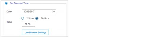
Figure 5-58 Set Date and Time window
• If you are using an NTP server, select Set NTP Server IP Address and then enter the IP address of the NTP server, as shown in Figure 5-59.
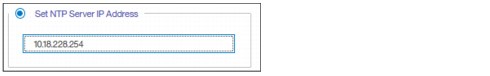
Figure 5-59 Set NTP Server IP Address window
4. Click Save.
Licensing
The base license that is provided with your system includes the use of its basic functions. However, the extra licenses can be purchased to expand the capabilities of your system. Administrators are responsible for purchasing extra licenses and configuring the systems within the license agreement, which includes configuring the settings of each licensed function on the system.
The IBM Storwize V7000 supports enclosure-based licensing, which allows the use of certain licensed functions that are based on the number of enclosures that are indicated in the license.
Complete the following steps to view or configure the licensing settings:
1. From the main Settings pane, move the pointer over Settings and click System.

Figure 5-60 Licensing window
3. In the Licensed Functions pane, you can view or set the licensing options for the IBM Storwize V7000 for the following elements (limits are in TiB):
– External Virtualization
Specifies the number of enclosures of external storage systems that are attached to your IBM Storwize V7000. Data can be migrated from existing storage systems to your system that uses the external virtualization function within 45 days of purchase of the system without purchase of a license. After 45 days, any ongoing use of the external virtualization function requires a license for each enclosure in each external system.
The system does not require an external virtualization license for external enclosures that are only being used to provide managed disks for a quorum disk and are not providing any capacity for volumes.
– Remote Mirroring Limit
The remote-mirroring function configures a relationship between two volumes. This function mirrors updates that are made to one volume to another volume. The volumes can be in the same system or on two different systems.
The remote-mirroring function is licensed per enclosure. It allows the use of remote-mirroring functions on the total number of enclosures that are licensed. The total number of enclosures must include the enclosures on external storage systems that are licensed for virtualization and the number of control and expansion enclosures that are part of your local system.
The license settings apply only to the system on which you are configuring license settings. For remote-copy partnerships, a license is also required on any remote systems that are in the partnership.
– Real-time Compression Limit
One license is required for each control or expansion enclosure and each enclosure in any external storage systems that use compression.
– Transparent Cloud Tiering
Enter the total number of enclosures that are licensed to create snapshots of volume data to cloud storage.
– Encryption License
In addition to these enclosure-based licensed functions, the system also supports encryption through a key-based license. Key-based licensing requires an authorization code to activate encryption on the system. Only certain models of the control enclosures support encryption.
During initial setup, you can select to activate the license with the authorization code. The authorization code is sent with the licensed function authorization documents that you receive after purchasing the license. These documents contain the authorization codes that are required to obtain keys for the encryption function that you purchased for your system.
Encryption is activated on a per system basis and an active license is required for each control enclosure that uses encryption. During system setup, the system detects any SAS attached enclosures and applies the license to these enclosures. If additional control enclosures are added and require encryption, additional encryption licenses need to be purchased and activated.
Update System
The update procedure using the GUI is described in detail in Chapter 13, “RAS, monitoring, and troubleshooting” on page 663.
VMware Virtual Volumes
IBM Spectrum Virtualize V7.6 and later is able to manage VMware vSphere VVOLs directly in cooperation with VMware. It enables VMware virtual machines to get the assigned disk capacity directly from IBM Storwize V7000 rather than from the ESXi data store. That technique enables storage administrators to control the appropriate usage of storage capacity, and to enable enhanced features of storage virtualization directly to the virtual machine (such as replication, thin-provisioning, compression, encryption, and so on).
VVOL management is enabled in IBM Storwize V7000 in the System section, as shown in Figure 5-61. The NTP server must be configured before enabling VVOL management. It is strongly advised to use the same NTP server for ESXi and for IBM Storwize V7000.

Figure 5-61 Enabling VVOLs management
|
Restriction: You cannot enable VVOLs support until the NTP server is configured in Storwize V7000.
|
For a quick-start guide to VVOLs, see Quick-start Guide to Configuring VMware Virtual Volumes for Systems Powered by IBM Spectrum Virtualize, REDP-5321.
In addition, see Configuring VMware Virtual Volumes for Systems Powered by IBM Spectrum Virtualize, SG24-8328.
IP Quorum
Starting with IBM Spectrum Virtualize V7.6, a new feature was introduced for enhanced stretched systems, the IP Quorum application. Using an IP-based quorum application as the quorum device for the third site, no Fibre Channel connectivity is required. Java applications run on hosts at the third site.
To start with IP Quorum, complete the following steps:
1. If your IIBM Storwize V7000 is configured with IP addresses version 4, click Download IPv4 Application, or select Download IPv6 Application for systems running with IP version 6. In our example, IPv4 is the option as shown in Figure 5-62.

Figure 5-62 IP Quorum
2. Click Download IPv4 Application and the IBM Spectrum Virtualize generates an IP Quorum Java application as shown in Figure 5-63. The application can be saved and installed in a host that is to run the IP quorum application.
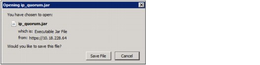
Figure 5-63 IP Quorum Java Application
3. On the host, you must use the Java command line to start the IP quorum application. Change to the folder where the application is located and run java -jar ip_quorum.jar.
I/O Groups
For ports within an I/O group, you can enable virtualization of Fibre Channel ports that are used for host I/O operations. With N_Port ID virtualization (NPIV), the Fibre Channel port consists of both a physical port and a virtual port. When port virtualization is enabled, ports do not come up until they are ready to handle I/O, which improves host behavior around node unpends. In addition, path failures due to an offline node are masked from hosts.
The target port mode on the I/O group indicates the current state of port virtualization:
•Enabled: The I/O group contains virtual ports that are available to use.
•Disabled: The I/O group does not contain any virtualized ports.
•Transitional: The I/O group contains both physical Fibre Channel and virtual ports that are currently being used. You cannot change the target port mode directly from enabled to disabled states, or vice versa. The target port mode must be in transitional state before it can be changed to either disabled or enabled states.
The system can be in the transitional state for an indefinite period while the system configuration is changed. However, system performance can be affected because the number of paths from the system to the host doubled. To avoid increasing the number of paths substantially, use zoning or other means to temporarily remove some of the paths until the state of the target port mode is enabled.
The port virtualization settings of I/O groups are available by clicking Settings → System → I/O Groups as shown in Figure 5-64.
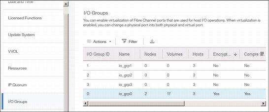
Figure 5-64 I/O Group port virtualization
You can change the status of the port by right-clicking the wanted I/O group and selecting Change Target Port, as shown in Figure 5-65.
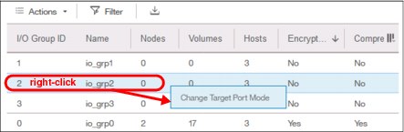
Figure 5-65 Changing port mode
Domain Name Server
Introduced within V7.8, IBM Spectrum Virtualize allows domain name server (DNS) entries to be manually set up in the IBM Storwize V7000. The information about the DNS servers in the IBM Storwize V7000 helps the system to access the DNS servers to resolve names of the computer resources that are in the external network.
To view and configure DNS server information in IBM Spectrum Virtualize, complete the following steps:
1. In the left pane, click the DNS icon and enter the IP address and the Name of each DNS server. The IBM Spectrum Virtualize supports up two DNS Servers, IPv4 or IPv6. See Figure 5-66.
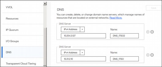
Figure 5-66 DNS information
2. Click Save after you complete entering the DNS server information.
Transparent Cloud Tiering
Transparent cloud tiering is a licensed function that enables volume data to be copied and transferred to cloud storage. The system supports creating connections to cloud service providers to store copies of volume data in private or public cloud storage.
With transparent cloud tiering, administrators can move older data to cloud storage to free up capacity on the system. Point-in-time snapshots of data can be created on the system and then copied and stored on the cloud storage. An external cloud service provider manages the cloud storage, which reduces storage costs for the system. Before data can be copied to cloud storage, a connection to the cloud service provider must be created from the system.
A cloud account is an object on the system that represents a connection to a cloud service provider by using a particular set of credentials. These credentials differ depending on the type of cloud service provider that is being specified. Most cloud service providers require the host name of the cloud service provider and an associated password, and some cloud service providers also require certificates to authenticate users of the cloud storage.
Public clouds use certificates that are signed by well-known certificate authorities. Private cloud service providers can use either self-signed certificate or a certificate that is signed by a trusted certificate authority. These credentials are defined on the cloud service provider and passed to the system through the administrators of the cloud service provider. A cloud account defines whether the system can successfully communicate and authenticate with the cloud service provider by using the account credentials.
If the system is authenticated, it can then access cloud storage to either copy data to the cloud storage or restore data that is copied to cloud storage back to the system. The system supports one cloud account to a single cloud service provider. Migration between providers is not supported.
|
Note: Important: Before enabling Transparent Cloud Tiering, consider the following requirements:
•Ensure that DNS server is configured on your system and accessible.
•Determine whether your company’s security policies require enabled encryption. If yes, make sure that the encryption licenses are properly installed and encryption enabled.
|
Each cloud service provider requires different configuration options. The system supports the following cloud service providers:
•SoftLayer®
•OpenStack Swift
•Amazon S3
To view your IBM Spectrum Virtualize cloud provider settings, from the IBM Storwize V7000 Settings pane, move the pointer over Settings and click System, then select Transparent Cloud Tiering, as shown in Figure 5-67.

Figure 5-67 Transparent cloud tiering settings
Using this view, you can enable and disable features of your Transparent Cloud Tiering and update the system information concerning your cloud service provider. This pane allows you to set a number of options:
•Cloud service provider
•Object Storage URL
•The Tenant or the container information that is associated to your cloud object storage
•User name of the cloud object account
•API Key
•The container prefix or location of your object
•Encryption
•Bandwidth
5.10.4 Support menu
Use the Support pane to configure and manage connections and upload support packages to the support center.
Two options are available from the menu:
•Support assistance This option enables support personnel to access the system to complete troubleshooting and maintenance tasks. You can configure either local support assistance, where support personnel visit your site to fix problems with the system, or remote support assistance. Both local and remote support assistance use secure connections to protect data exchange between the support center and system. More access controls can be added by the system administrator.
•Support Package: If support assistance is configured on your systems, you can either automatically or manually upload new support packages to the support center to help analyze and resolve errors on the system.
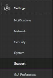
Figure 5-68 Support menu
More details about how the Support menu helps with troubleshooting of your system or how to make a backup of your systems are provided in Chapter 13, “RAS, monitoring, and troubleshooting” on page 663.
5.10.5 Setting GUI preferences
As shown in Figure 5-69, the menu GUI Preferences consists of two options:
•Login/Message
•General

Figure 5-69 GUI Preferences
Login message
IBM Spectrum Virtualize V7.6 and later enables administrators to configure the welcome banner (login message). This is a text message that appears either in the GUI login window or at the CLI login prompt.
The content of the welcome message is helpful when you need to notify users about some important information about the system, such as security warnings or a location description. To define and enable the welcome message by using the GUI, edit the text area with the message content and click Save (Figure 5-70).

Figure 5-70 Enabling login message
The result of the action before is shown in Figure 5-71.
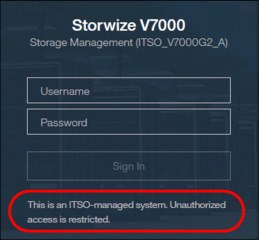
Figure 5-71 Welcome message in GUI
The banner message also appears in the CLI login prompt window as shown in Figure 5-72.

Figure 5-72 Banner message in CLI
General settings
The General Settings menu allows the user to refresh the GUI cache, to set the low graphics mode option, and to enable advanced pools settings.
Complete the following steps to configure general GUI preferences:

Figure 5-73 General GUI Preferences window
2. You can configure the following elements:
– Refresh GUI cache
This option causes the GUI to refresh all of its views and clears the GUI cache. The GUI looks up every object again.
– Clear Customization
This option deletes all GUI preferences that are stored in the browser and restores the default preferences.
– IBM Knowledge Center
You can change the URL of IBM Knowledge Center for IBM Spectrum Virtualize.
– The accessibility option enables Low graphic mode when the system is connected through a slower network.
– Advanced pool settings allow you to select the extent size during storage pool creation.
– Default logout time in minutes after inactivity in the established session.
5.11 Additional frequent tasks in GUI
This section describes additional options and tasks available in the GUI of your IBM Storwize V7000 that have not been discussed previously in this chapter and that are frequently used by administrators.
5.11.1 Renaming components
These sections provide guidance on how to rename your system and canisters.
Renaming IBM Storwize V7000 system
All objects in the system have names that are user-defined or system-generated. Choose a meaningful name when you create an object. If you do not choose a name for the object, the system generates a name for you. A well-chosen name serves both as a label for an object and as a tool for tracking and managing the object. Choosing a meaningful name is important if you decide to use configuration backup and restore.
When you choose a name for an object, apply the following naming rules:
•Names must begin with a letter.
|
Important: Do not start names by using an underscore (_) character even though it is possible. The use of the underscore as the first character of a name is a reserved naming convention that is used by the system configuration restore process.
|
•The first character cannot be numeric.
•The name can be a maximum of 63 characters with the following exceptions: The name can be a maximum of 15 characters for Remote Copy relationships and groups. The lsfabric command displays long object names that are truncated to 15 characters for nodes and systems. V5.1.0 systems display truncated volume names when they are partnered with a version V6.1.0 or later system that has volumes with long object names (lsrcrelationshipcandidate or lsrcrelationship commands).
•Valid characters are uppercase letters (A - Z), lowercase letters (a - z), digits (0 - 9), the underscore (_) character, a period (.), a hyphen (-), and a space.
•Names must not begin or end with a space.
•Object names must be unique within the object type. For example, you can have a volume called ABC and an MDisk called ABC, but you cannot have two volumes called ABC.
•The default object name is valid (object prefix with an integer).
•Objects can be renamed to their current names.
To rename the system from the System pane, complete the following steps:

Figure 5-74 Actions on the System pane
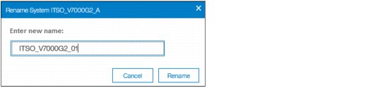
Figure 5-75 Rename the system
|
System name: You can use the letters A - Z and a - z, the numbers 0 - 9, and the underscore (_) character. The clustered system name can be 1 - 63 characters.
|
3. If you are certain that you want to change the system name, then click Yes.
|
Warning: When you rename your system, the iSCSI name (IQN) automatically changes because it includes system name by default. Therefore, this change needs additional actions on iSCSI-attached hosts.
|
Rename a node canister
To rename a node canister, complete these steps:
1. Click in the arrow to rotate the control enclosure as shown in Figure 5-76.

Figure 5-76 Rotate the control enclosure

Figure 5-77 Rename node canister
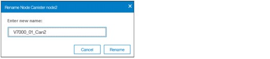
Figure 5-78 Enter the new name of the node
|
Warning: Changing the node canister name causes an automatic IQN update and requires the reconfiguration of all iSCSI-attached hosts.
|
5.11.2 Working with enclosures
The following section illustrates how to add or remove expansion enclosure to/from your IBM Storwize V7000 system.
Adding an enclosure
After the expansion enclosure is properly attached and powered on, proceed with the following steps to activate it in the system:
1. In the System pane available from the Monitoring menu, click the empty enclosure item. Only correctly attached and powered on enclosures appear in the window, as shown in Figure 5-79.

Figure 5-79 Newly detected expansion enclosure
2. The systems lists all detected expansion enclosures (Figure 5-80).
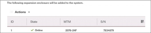
Figure 5-80 List of detected enclosures
3. The summary table provides information about your selection. After it is confirmed, the enclosure is added to the system and ready for use (Figure 5-81).
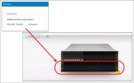
Figure 5-81 Enclosure successfully initialized
Removing enclosure
The enclosure removal procedure includes its logical detachment from the system using GUI and physical unmount from the rack. The IBM Storwize V7000 guides you through this process:
1. In the System pane available from the Monitoring menu, right-click the enclosure that you want to detach and select Remove (Figure 5-82).
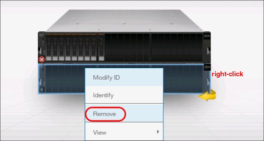
Figure 5-82 Selecting enclosure for removal
2. The system asks if you want to remove the enclosure. All disk drives in the removed enclosure must be in the Unused state. Otherwise, the removal process fails (Figure 5-83).

Figure 5-83 Confirm the removal
3. After the enclosure is logically removed from the system (set to umanaged state), the IBM Storwize V7000 reminds you about steps necessary for physical removal, such as power off, uncabling, dismantling from the rack, and secure handling (Figure 5-84).

Figure 5-84 Enclosure removed
As part of the enclosure removal process, consult your company security policies on how to handle sensitive data on removed storage devices before they leave the secure data center. Most companies require data to be either encrypted or logically shredded.
..................Content has been hidden....................
You can't read the all page of ebook, please click here login for view all page.