Chapter 4
Introduction to Industrial Control Systems and Operations
Abstract
You cannot protect something unless you know what it is, and how it is supposed to behave. So what is an industrial network, and how does it work? A discussion of industrial control system devices and systems, control logic, process loops, and more.
Keywords
Control Loop
Industrial automation
ICS
DCS
SCADA
process control
industrial control system
control logic
ladder logic
step logic
Information in this chapter
• System Assets
• System Operations
• Process Management
• Safety Instrumented Systems
• Smart Grid Operations
• Network Architectures
It is necessary to have a basic understanding of how commonly used ICS components interact within an industrial network in addition to knowledge of how industrial network protocols operate. This information may seem overly basic for operators of industrial control systems. It is also important to remember that “how control systems are connected” and “how they should be connected” are not always the same. One can quickly assess whether there are any basic security flaws in an industrial network design by taking a short step back to the basics. This requires an understanding of the specific assets, architectures, and operations of a typical industrial network.
System assets
The first step is to understand the components used within industrial networks and the roles that they play. These devices discussed in this chapter, include field components such as sensors, actuators, motor drives, gauges, indicators and control system components, such as programmable logic controllers (PLCs), remote terminal units (RTUs), intelligent electronic device (IED), human–machine interfaces (HMIs), engineering workstations, application servers, data historians, and other business information consoles or dashboards.
Programmable logic controller
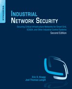
A programmable logic controller is a specialized industrial computer used to automate functions within manufacturing facilities. Unlike desktop computers, PLCs are typically physically hardened (making them suitable for deployment in a production environment) and may be specialized for specific industrial uses with multiple specialized inputs and outputs. PLCs do not typically use a commercially available operating system (OS). They instead rely on specific application programs that allow the PLC to function automatically generating output actions (e.g. to pump motors) in response to specific inputs (e.g. from sensors) with as little overhead as possible. PLCs were originally designed to replace electromechanical relays. Very simple PLCs may be referred to as programmable logic relays (PLRs). Figure 4.1 illustrates the typical structure of a PLC.
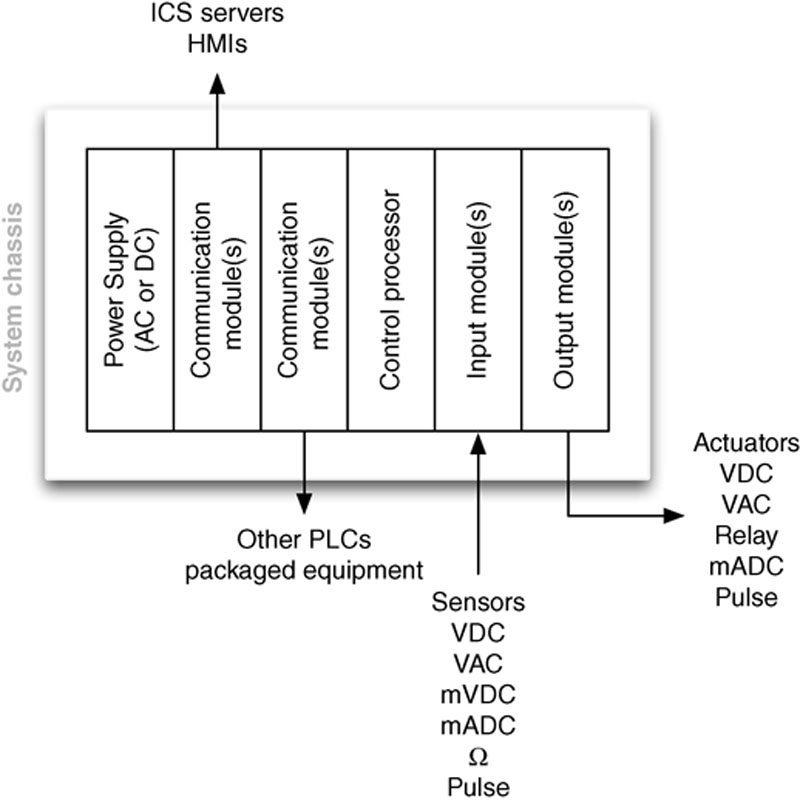
Figure 4.1 Components of a programmable logic controller.
Programmable logic controllers typically control real-time processes, and so they are designed for simple efficiency. For example, in plastic manufacturing, a catalyst may need to be injected into a vat when the temperature reaches a very specific value. If processing overhead or other latency introduces delay in the execution of the PLC’s logic, it would be very difficult to precisely time the injections, which could result in quality issues. For this reason, the logic used in PLCs is typically very simple and is programmed according to an international standard set of languages as defined by IEC-61131-3.
Ladder diagrams
Programmable logic controllers can use “ladder logic” or “ladder diagrams (LD),” which is a simplistic programming language included within the IEC-61131-3 standard that is well suited for industrial applications. Ladder logic gets its name from the legacy method of implementing discrete logic via electromechanical relays and was initially referenced as “relay ladder logic.” Ladder logic can be thought of as a set of connections between inputs (relay contacts) and outputs (relay coils). Ladder logic follows a relay function diagram, as shown in Figure 4.2. A path is traced on the left side, across “rungs” consisting of various inputs. If an input relay is “true” the path continues, and if it is “false” it does not. If the path to the right side completes (there is a complete “true” path across the ladder), the ladder is complete and the output coil will be set to “true” or “energized.” If no path can be traced, then the output remains “false,” and the relay remains “de-energized.”1 This was implemented before PLCs, with a (+) bus on the left-hand side and a (−) bus on the right-hand side. The “path” just described represented electrical current flow through the logic.
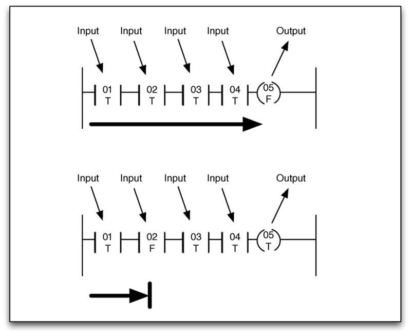
Figure 4.2 Example of simple ladder logic with both complete and incomplete conditions.
The PLC applies this ladder logic by looking at inputs from discrete devices that are connected to the manufacturing equipment, and performing a desired output function based on the “state” of these inputs. These outputs are also connected to manufacturing equipment, such as actuators, motor drives, or other mechanical equipment. PLCs can use a variety of digital and analog communications methods, but typically use a fieldbus protocol, such as Modbus, ControlNet, EtherNet/IP, PROFIBUS, PROFINET or similar (see Chapter 6, “Industrial Network Protocols”). A switch is used to convert an analog or “continuous” value from a sensor to a “discrete” on or off value by comparing the input to a set point. If a set point is satisfied, the input is considered “true,” and if it is not it is considered “false.” Processes defined by ladder logic can be simple or very complex. For example, an “or” condition can allow the rung to complete based on an alternate input condition, as shown in Figure 4.3.
Figure 4.3 Example of simple ladder logic containing an “OR” condition.
When an output coil is finally reached it becomes “true,” and the PLC activates the output. This allows the PLC to automate a function (e.g. turning a pump on or off) based on set point parameters (e.g. high and low water levels within a tank).2
Internal relays may also be used within a PLC; these relays, unlike input relays, do not use inputs from the physical plant, but rather are used by the ladder logic to lock an input on (true) or off (false) depending upon other conditions of the program. PLCs also use a variety of other function “blocks” including counters, timers, flip-flops, shift registers, comparators, mathematical expressions/functions, and many others allowing PLCs to act in defined cycles or pulses, as well as storage.3
Sequential function charts
Another programming language used by PLCs and defined within the IEC-61131-3 standard is “sequential logic” or “sequential function charts (SFC).” Sequential logic differs from ladder logic in that each step is executed in isolation and progresses to the next step only upon completion, as opposed to ladder logic where every step is tested in each scan. This type of sequential programming is very common in batch-oriented operations. Other common languages defined by IEC-61131-3 include “structured text (ST),” “function block diagram (FBD)” and “instruction list (IL)” methods. No matter what programming language is used with a particular PLC, the end goal is ultimately to automate the legacy electromechanical functions common in industrial systems by checking inputs, applying logic (the program), and adjusting outputs as appropriate,4 as shown in Figure 4.4.
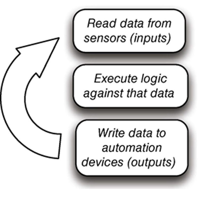
Figure 4.4 PLC operational flow diagram.
The logic used by the PLC is created using a software application typically installed on an engineering workstation that combines similar tools, or may be combined with other system functions like the HMI. The program is compiled locally on the computer, and then downloaded from the computer to the PLC by either direct serial (RS-232) or Ethernet connections, where the logic code is loaded onto the PLC. PLCs can support the ability to host both the source and compiled logic programs, meaning that anyone with the appropriate engineering software could potentially access the PLC and “upload” the logic.
Remote terminal unit
A remote terminal unit typically resides in a substation, along a pipeline, or some other remote location. RTUs monitor field parameters and transmit that data back to a central monitoring station—typically either a master terminal unit (MTU) that may be an ICS server, a centrally located PLC, or directly to an HMI. RTUs commonly include remote communications capabilities consisting of a modem, cellular data connection, radio, or other wide area communication technology. They are often installed in locations that may not have easy access to electricity, and can be supplied with local solar power generation and storage facilities. It is common for RTUs to be placed outdoors, which means they are subjected to extreme environmental conditions (temperature, humidity, lightning, animals, etc.). Their communications bandwidth is generally limited, and in order to maximize the amount of information transmitted, they favor protocols that support “report by exception” or other “publish/subscribe” mechanisms to minimize unnecessary repetition or transmission of the data as described in Chapter 6, “Industrial Network Protocols.”
Remote terminal units and PLCs continue to overlap in capability and functionality, with many RTUs integrating programmable logic and control functions, to the point where an RTU can be thought of as a remote PLC that has been combined with integrated telecommunications equipment.
Intelligent electronic device
Each industry has unique physical and logical requirements, and for this reason, ICS equipment varies to some extent from industry to industry. A pipeline typically has pumping (liquids) or compressor (gases) stations distributed along the pipeline. The RTU is well suited for installation in this application as was previously described. The electric utility sector has a similar requirement except that instead of pumping stations, their transmission lines consist of numerous electrical substations that are distributed throughout the grid to manage electrical loads, and provide local isolation when needed. The intelligent electronic device was developed for these types of installations that require not only local direct control functionality and integrated telecommunications support, but also can be installed in areas that involve high-voltage energy sources and the associated electrical “noise” that is typically present in these environments.
As with all technology, IEDs are growing more and more sophisticated over time, and an IED may perform other tasks, blurring the line between device types. To simplify things for the purposes of this book, an IED can be considered to support a specific function (i.e. substation automation) within the overall control system, whereas RTUs and PLCs are designed for general use (i.e. they can be programmed to control the speed of a motor, to engage a lock, to activate a pump, or rail crossing gate).
As technology evolves, the line blurs between the PLC, RTU, and IED, as can be seen in Emerson Process Management’s ROC800L liquid hydrocarbon remote controller shown in Figure 4.5. This device performs measurement, diagnostics, remote control, and telecommunications in a single device that supports several programmable languages.
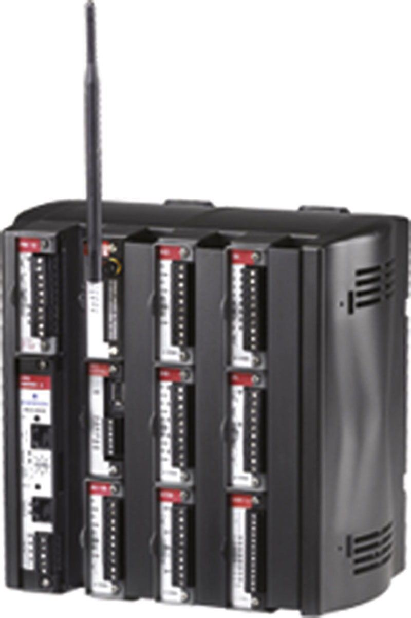
Figure 4.5 Emerson Process Management’s ROC800L liquid hydrocarbon remote controller.
Human–machine interface
Human–machine interfaces are used as an operator’s means to interact with PLCs, RTUs, and IEDs. HMIs replace manually activated switches, dials, and other electrical controls with graphical representations of the digital controls used to sense and influence that process. HMIs allow operators to start and stop cycles, adjust set points, and perform other functions required to adjust and interact with a control process. Because the HMI is software based, they replace physical wires and controls with software parameters, allowing them to be adapted and adjusted very easily. Figure 4.6 shows how the HMI integrates with the overall ICS architecture as explained so far.
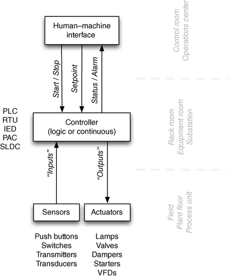
Figure 4.6 Human–machine interface functionality.
Human–machine interfaces are modern software applications that come in two predominant form-factors. The first runs on modern operating systems like Windows 7, and are capable of performing a variety of functions. The other form combines an industrial hardened computer, local touch panel, and is packaged to support door or direct panel mounting. These devices typically utilize an embedded operating system like Windows Embedded (CE, XP, 7, 8, Compact) and are programmed with a separate computer and associated engineering software. They act as a bridge between the human operator and the complex logic of one or more PLCs, allowing the operator to focus on how the process is performing rather than on the underlying logic that controls many functions across distributed and potentially complex processes from a centralized location. To accomplish this, the user interface will graphically represent the process being controlled, including sensor values and other measurements, and visible representation of output states (which motors are on, which pumps are activated, etc.).
Humans interact with the HMI through a computer console, but do not generally authenticate to the station with a password, because during an abnormal event, a password lockout or any other mechanism that would block access to the HMI would be considered unsafe and violates the basic principle of guaranteed availability. At first this may seem insecure, but considering that these devices are typically installed in areas that possess strong physical security and are only operated by trained and authorized personnel, the resulting risk is tolerable. Because HMIs provide supervisory data (visual representation of a control process’s current state and values) as well as control (i.e. set point changes), user access controls are usually part of the ICS allowing specific functions to be locked out to specific users. The HMI interacts either directly or indirectly through an ICS server with one or more controllers using industrial protocols, such as OLE for Process Control (OPC) or fieldbus protocols, such as EtherNet/IP or Modbus (see Chapter 6, “Industrial Network Protocols”).
There are other more appropriate methods of securing HMIs from both unauthorized access by the intended user, as well as unauthorized access resulting from a cyber event. Many vendors are aware of the importance of least privileges, and now are providing local- and domain-based Group Policies that can be installed to restrict the authorization granted at the local workstation. Microsoft provides the ability to enforce these policies either by computer or user, making this well suited for workstations placed in common areas. These policies can not only restrict the execution of local applications and the functionality of the Windows GUI, but also prevent unauthorized access to removable media and USB access ports. The security of the industrial process therefore relies heavily on access control and host security of the HMI and the underlying control system.
Supervisory workstations
A supervisory workstation collects information from assets used within a control system and presents that information for supervisory purposes. Unlike an HMI, a supervisory workstation is primarily read-only. These workstations have no control element to interact directly with the process, only the presentation of information about that process. These workstations are typically authorized with the ability to change certain parameters that an operator is usually not allowed to manipulate. Examples may include alarm limits, and in some situations, process set points.
A supervisory workstation will consist of either an HMI system (with read-only or supervisory access restrictions) or a dashboard or workbook from a data historian (a device specifically designed to collect a running audit trail of control system operational data). Supervisory workstations can reside in a variety of locations throughout the industrial networks, as well as the ICS semitrusted demilitarized zones (DMZ) or business networks, up to and including Internet-facing web portals and Intranets (see “Control Processes” in this chapter).
Data historian
A data historian is a specialized software system that collects point values, alarm events, batch records, and other information from industrial devices and systems and stores them in a purpose-built database. Most ICS vendors including ABB, Areva, Emerson, GE, Honeywell, Invensys, Rockwell, Schneider, Siemens, and others provide their own proprietary data historian systems. There are also third-party industrial data historian vendors, such as Aspen Technologies (www.aspentech.com), Canary Labs (www.canarylabs.com), Modiüs (www.modius.com), and OSIsoft (www.osisoft.com), which interoperate with ICS assets and even integrate with proprietary ICS historians in order to provide a common, centralized platform for data historization, analysis, and presentation.
Data that are historized and stored within a data historian is referred to as “tags” and can represent almost anything—the current speed of a motor or turbine, the rate of airflow through a heating, ventilation, and air-conditioning (HVAC) system, the total volume in a mixing tank, or the specific volumes of injected chemical catalysts in a tank. Tags can even represent human-generated values, such as production targets, acceptable loss margins, and manually collected data.
Information used by both industrial operations and business management is often replicated across industrial and business networks and stored in data historians. This can represent a security risk since a data historian in a less secure zone (i.e. the business network) could be used as a vector into more secure zones (i.e. the ICS network). Data historians should therefore be hardened to minimize vulnerabilities, and utilize strict user and network access controls.
OSIsoft holds a dominant position in the data historian market at the time of this writing, with 65% market penetration in global industrial automated systems.5 The OSIsoft PI System integrates with many IT and OT systems including other data historians, and is a premium target for attack. Applying the latest updates and patches can minimize vulnerabilities. Properly isolating and securing data historian components that connect with assets in less trusted networks within a semitrusted DMZ significantly help to minimize accessibility. It is important to consider special component-level cyber security testing of assets, such as data historians, in order to ensure that they do not introduce vulnerabilities not common in the traditional public disclosure realm (e.g. Microsoft monthly security bulletins) to the ICS. For more information about the role of data historians within control system operations, see “Control Processes: Feedback Loops” and “Control Processes: Business Information Management” later in the chapter.
Business information consoles and dashboards
Business information consoles are extensions of supervisor workstations designed to deliver business intelligence to upper management. They typically consist of the same data obtained from HMI or data historian systems. A business information console in some cases may be a physical console, such as a computer display connected to an HMI or historian within the ICS DMZ, but physically located elsewhere (such as an executive office or administration building). The physical display in these cases is connected using a remote display or secure remote keyboard video mouse (KVM) switching system. Business information may also be obtained by replicating HMI or data historian systems within the business network or by publishing exported information from these systems using an intermediary system. An example of such an intermediary system may be exporting values from the data historian into a spreadsheet and then publishing that spreadsheet to a corporate information portal or intranet. This publishing model may be streamlined and automated depending upon the sophistication of the data historian. Many vendors have developed special platforms that allow the reuse of process-level HMI graphics to be deployed and populated with real-time and historical data via replicated read-only servers placed on less-secure networks using web services (e.g. HTML and HTTPS) for the presentation of data to business network users. Any published data should be access controlled, and any open communication path from ICSs to more openly accessible workstations or portals should be carefully controlled, isolated, and monitored.
Other assets
There are many other assets that may be connected to an industrial network other than PLCs, RTUs, HMIs, historians, and workstations. Devices, such as printers and print servers, may be connected to corporate networks, or they may connect directly to a control loop. Access control systems, such as badge scanners and biometric readers, may be used along with closed-circuit television (CCTV) systems all networked (probably over TCP/IP) together. There are also common infrastructure components like Active Directory and Time Servers that are deployed throughout an industrial network.
Although this book does not attempt to cover every aspect of every device that may be present within an industrial network, it is important to recognize that every device has an attack surface, and therefore a potential impact to security and should be assessed if
1. It is connected to a network of any kind (including wireless networks originating from the device itself).
2. It is capable of transporting data or files, such as removable media (mobile devices).
Even the most seemingly harmless devices should be assessed for potential security weaknesses—either inherent to the device itself, or a result of configuration of the device. Check the documentation of devices to make sure that they do not have wireless capabilities, and if so, secure or disable those features. Many commercially produced devices contain multipurpose microprocessors, which may contain radio or Wi-Fi antennae receivers or transmitters even if the device is not intended for wireless communication. Many of today’s Wi-Fi components include both wireless LAN (WLAN) and Bluetooth capability. This is because it is sometimes more cost-effective for a supplier to use a commercial, off-the-shelf (COTS) microprocessor with unneeded capabilities. The manufacturer may never enable those capabilities, but if the hardware exists malicious actors can use it as an attack vector.6
System operations
All of the industrial network protocols, devices, and topologies discussed up to this point are used to create and automate some industrial operation: refining crude oil, manufacturing a consumer product, purifying water, generating electricity, synthesizing and combining chemicals, and so on. A typical industrial operation consists of several layers of programmed logic designed to manipulate mechanical controls in order to automate the operation. Each specific function is automated by what is commonly referred to as a control loop. Multiple control loops are typically combined or stacked together to automate larger processes.
Control loops
Industrial controllers are made up of many specific automated processes, called control loops. The term “loop” derives from the ladder logic that is widely used in these systems. A controller device, such as a PLC, is programmed with specific logic. The PLC cycles through its various inputs, applying the logic to adjust outputs, and then starts over scanning the inputs. This repetitive control action is necessary in order to perform a specific function. This cycle or “loop” automates that function.
In a closed loop, the output of the process affects the inputs, fully automating the process. For example, a water heater is programmed to heat water to a set point of 90°C. An electric heating coil is energized to heat the water, and the water temperature is measured and fed back as an input into the control process. When 90°C is reached, the heater turns off the heating coil, and continues to monitor the temperature until it drops below the set point. In an open loop, the input from the process (temperature in this case) does not affect the outputs (the heating coil). Stated another way, closed loops provide automated control whereas open loops provide manual control.
Control loops can be simple, checking a single input, as illustrated in Figures 4.7 and 4.8. For example, a simple loop in an automated lighting process might check a single input (e.g. a light sensor to measure ambient light) and adjust a single output (e.g. the switch controlling flow of electricity to a lamp). Complex loops might use multiple inputs (e.g. pressure, volume, flow, and temperature sensors) and adjust multiple outputs (e.g. valves and pump motors) to perform a function that is inherently more complex. An example of such a complex loop might be controlling water level (input) in a boiler drum based on steam demand (input) and feedwater inlet flow (input/output) variations. There are actually multiple control loops in this case applied to perform a single control function. As control complexity increases, control loops may be distributed across multiple controllers requiring critical “peer-to-peer” communications across the network.
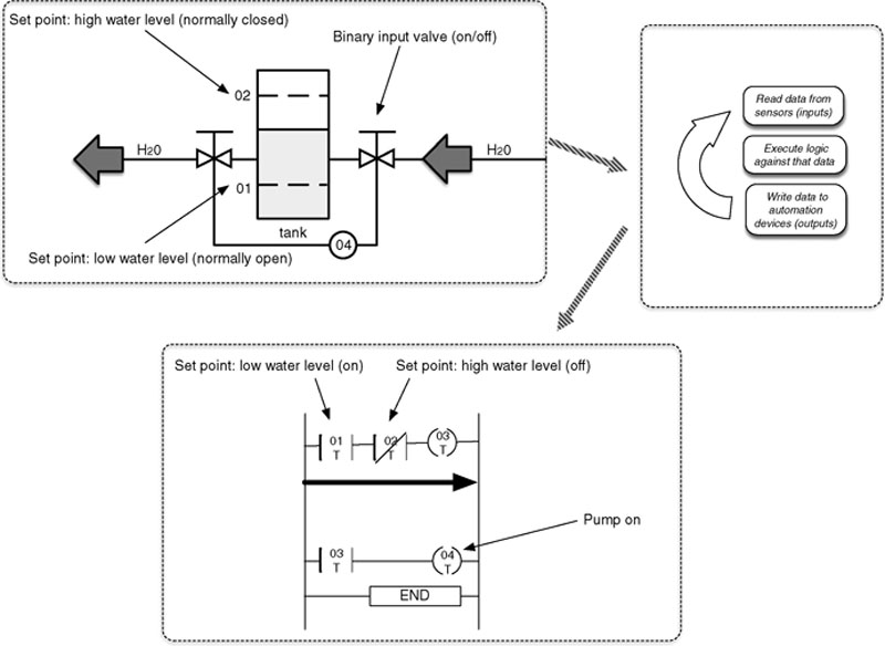
Figure 4.7 A simplified control loop in the “ON” state showing the applied ladder logic.
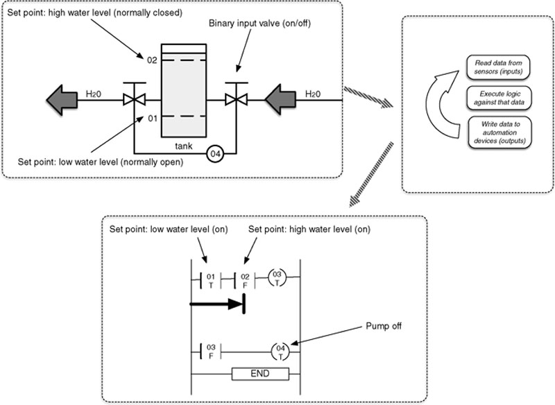
Figure 4.8 A simplified control loop in the “OFF” state showing the applied ladder logic.
Control loops can also be complex, as shown in Figure 4.9. This particular example illustrates several common aspects of process control, including improved variable accuracy through compensation techniques, and stable performance through feed-forward and cascade control strategies. Figure 4.9 shows how increasing or decreasing make-up water into the drum is controlled to account for fluctuations in steam demand. Feed-forward techniques are used to account for the lag time associated with heating water into steam.
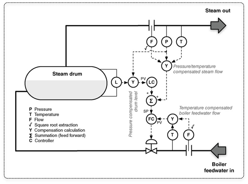
Figure 4.9 A more “Complex” control loop typical in process control.
Control processes
A “control process” is a general term used to define larger automated processes within an industrial operation. Many control processes may be required to manufacture a product or to generate electricity, and each control process may consist of one or many control loops. For example, one process might be to inject an ingredient into a mixer utilizing a control loop that opens a valve in response to volume measurements within the mixer, temperature, and other conditions. Several such processes or “steps” can automate the correct timing and combination of several ingredients, which in turn complete a larger process (to make a batter), which is known as a “phase.” The mixed batter might then be transported to other entirely separate control processes for baking, packaging, and labeling—all additional “phases” each containing their own unique “steps” and control loops.
Each process is typically managed using an HMI, which is used to interact with the process. An HMI will provide relevant readings from one or more control loops in a graphical fashion, requiring communication to all subordinate systems, including controllers like PLCs and RTUs. HMIs include readouts of sensors and other feedback mechanisms or “alarms” used to inform the operator of an action that is required in response to a process condition. HMIs are also used to issue direct control operations and provide mechanisms to adjust the set points of the ongoing control process.
An HMI usually controls a process consisting of many control loops. This means that the HMI’s network connectivity is typically heterogeneous, connecting to networks using routable protocols (TCP/IP) that include specialized ICS and fieldbus protocols, as well as other industrial network protocols to the various components that make up the ICS. HMIs are a common attack vector between the business and routable ICS networks.
Feedback loops
Every automated process relies on some degree of feedback both within a control loop and between a control loop or process and a human operator. Feedback is generally provided directly from the HMI used to control a specific process. A sample HMI graphical schematic of an automated process is shown in Figure 4.10. Feedback may also be centralized across multiple processes, through the collection, analysis, and display of information from many systems. For example, a refinery may have several crude oil and product storage tanks, each used in a replicated control process (e.g. local pump level and flow control). Information from each process can be collected and analyzed together to determine production averages, overages, and variations.
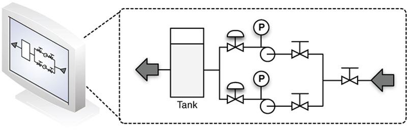
Figure 4.10 An HMI displaying current operational parameters.
Production information management
The centralized information management of an industrial control system is typically performed by one or more data historian systems. The process of removing data from the real-time environment of an automated industrial process and storing it over time is called “historizing” the data. Once historized, the information can be further analyzed using tools, such as Statistical Process Control (SPC) / Statistical Quality Control (SQC), either directly from within the data historian or by using an external analysis tool, such as a spreadsheet. Historical data can be replayed at some point in the future to compare past and present plant operations.
Specific ICS components may use their own data historian system to historize data locally. For example, an ABB 800xA control system may use the 800xA Information Management Historian, while an Emerson Ovation control system may use the Ovation Process Historian. Industrial operations tend to be heterogeneous in nature and require data to be collected and historized from multiple systems. These operations involve different processes that may utilize assets manufactured by different vendors, yet all processes need to be evaluated holistically in order to manage and fine-tune overall production operations. There also may be value in collecting information from other devices and systems within the industrial network, such as HVAC systems, CCTV, and Access Control systems. The shift from process-specific data historization to operation-wide business intelligence has led to the development of specialized features and functionality within data historians.
Business information management
Operational monitoring and analysis provides valuable information that can be used by plant management to fine-tune operations, improve efficiencies, minimize costs, and maximize profits. This drives a need for replication of operational data into the business network.
Supervisory data can be accessed using an HMI or a data historian client, with each presenting their own security challenges. HMIs provide supervisory and control capabilities, meaning that an HMI user with the proper authorization can adjust parameters of control process (see “Process Management”). By placing an HMI outside of the ICS DMZ, any firewalls, IDS/IPS, and other security monitoring devices that are in place need to be configured to allow the communication of the HMI into and out of the ICS DMZ. This effectively reduces the strength of the security perimeter between the industrial and business networks to user authentication only. If not properly deployed, a user account that is compromised on the business HMI system can be used to directly manipulate control process(es), without further validation from perimeter security devices. This can be mitigated to some extent by leveraging more of the ICS “authorization” capabilities that can restrict what a particular HMI is used to do on the system irrespective of any prior user authentication that has occurred. This can be used to restrict business network HMI users from any “write” or “change” operations that impact the process.
The use of a data historian for business intelligence management presents a similar concern. The security perimeter must be configured to allow communication between the data historian in the business network and the various systems within the ICS DMZ that need to be monitored. Best practices recommend that in this case, the only component in the DMZ connected to the historian on the business network is a historian. This allows for replication of historical data out of the DMZ via well-defined communication ports using a one-to-one relationship, while maintaining strict access control between the supervisory ICS components and the historian in the DMZ. Unlike an HMI, a data historian generally does not explicitly allow control of the process (however, some historians do support read and write capabilities to the ICS). The data historian instead provides a visual dashboard that can be configured to mimic the informational qualities and graphical representation of an HMI so that information about a process can be viewed in a familiar format.
Data are collected by a historian through a variety of methods including direct communication via industrial network protocols, such as Modbus, PROFIBUS, DNP3, and OPC (see Chapter 6, “Industrial Network Protocols”); history-oriented industrial protocols like OPC Historical Data Access (OPC-HDA); direct insertions in the data historian’s database using Object Linking and Embedding Database (OLEDB), Open Database Connectivity (ODBC), Java Database Connectivity (JDBC), and so on. Most data historians support multiple methods of data collection to support a variety of industrial applications. Once the information has been collected, it is stored within a database schema along with relevant metadata that helps to apply additional context to the data, such as batch numbers, shifts, and more depending upon the data historian’s available features, functionality, and licensing.
Data historians also provide access to long-term data using many of the same methods mentioned earlier. Dashboards utilizing technologies like Microsoft SharePoint are becoming common allowing historical information to be retrieved and presented via web services for display on clients using standard Internet browser capabilities (HTTP/HTTPS). Custom applications can be created to access historical data via direct SQL queries, and can be presented in almost any format, including binary files, XML, CSV, and so on.
Historized data can also be accessed directly via the data historian’s client application, as well as integrated at almost any level into supplementary Business Information Management Systems (BIMS). The Data Historian may in some cases be integrated with security information and event management systems (SIEMs), network management systems (NMSs), and other network and/or security monitoring systems.7
The Bandolier Project was funded by the US Department of Energy and implemented by DigitalBond to provide ICS owners the ability to optimize the security configuration of certain applications. Bandolier consists of a set of compliance files supported by the Nessus vulnerability scanner from Tenable Network Security that can be run against systems, including the OSIsoft PI Server, to determine the current configuration of an application versus the vendor’s recommended best practice.8
Process management
A control process is initially established through the programming of a controller and the building of a control loop. In a fully automated loop, the process is controlled entirely through the comparison of established set points against various inputs. In a water heater, a set point might be used to establish the high-temperature range of 90°C, and an input would take temperature measurements from a sensor within the water tank. The controller’s logic would then compare the input to the set point to determine whether the condition has been met (it is “true”) or not (it is “false”). The output or heating element would then be energized or de-energized.
An HMI is used by an operator to obtain real-time information about the state of the process to determine whether manual intervention is required to manage the control process by adjusting an output (open loop) or modifying established set points (closed loop). The HMI facilitates both, by providing software controls to adjust the various set points of a control loop while also providing controls to manually affect the output of the loop.
In the case of set point adjustments, the HMI software is used to write new set points in the programmable logic of the loop controller. This might translate to Function Code 6 (“Write Single Register”) in a Modbus system, although the specific protocol function is typically hidden from the operator, and performed as part of the HMI’s functionality. The HMI translates the function into human-readable controls presented within a graphical user interface (GUI), as represented in Figure 4.11.
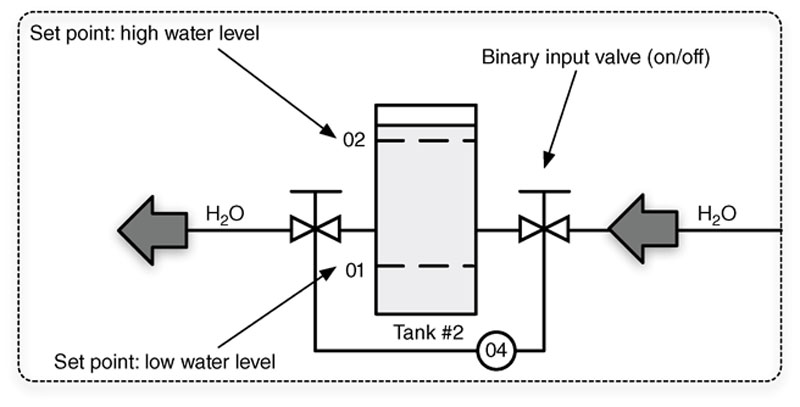
Figure 4.11 An HMI’s GUI representation of a control loop.
In contrast, the HMI could also be used to override a specific process and force an output, for example, using Function Code 5 (“Write Single Coil”) to write a single output to either the on (“true”) or the off (“false”) state.9 The specific function code used to write the output state is hidden from the operator.
This represents a significant security concern. If an attacker is able to successfully compromise the HMI, fully automated systems can be permanently altered through the manipulation of set points. For example, by changing the high-temperature set point to 100°C, the water in a tank could boil, potentially increasing the pressure enough to rupture the tank. An attacker can also force direct changes to a process loop’s output controls. In this example, the attacker could energize the water heater’s coil manually. In the case of Stuxnet, malware inserted into a PLC listened to PROFIBUS-DP communication looking for an indication of a specific frequency converter manufacturer and the device operating at a specific frequency range. If those conditions were found, multiple commands were sent to the controller, alternating the operating frequency and essentially sabotaging the process.11 It is important to understand that in both the water heater and Stuxnet examples just described, an attacker must have significant knowledge of the specific process and operational procedures in order to convert an HMI breach into an attack against the manufacturing process. Put another way, the attacker must know the exact register to change in order to alter the set point of the water heater from 90°C to 100°C. This makes a “casual” cyber-attack of this type much less probable, but should not be considered a defense against a targeted cyber-attack. It has been proven that sophisticated threat actors can and will obtain the knowledge necessary to launch a targeted attack of this type, and that “security by obscurity” cannot be considered a valid defensive strategy.
Safety instrumented systems
Safety instrumented systems (SIS) are deployed as part of a comprehensive risk management strategy utilizing layers of protection to prevent a manufacturing environment from reaching an unsafe operating condition. The basic process control system (BPCS) is responsible for discrete and continuous control necessary to operate a process within normal operational boundaries. In the event that an abnormal situation occurs that places the processing outside of these normal limits, the SIS is provided as an automated control environment that can detect and respond to the process event and maintain or migrate it to a “safe” state—typically resulting in equipment and plant shutdowns. As a final layer of protection, manufacturing facilities utilize significant physical protective devices including relief valves, rupture disks, flare systems, governors, and so on to act as a final level of safety prior to the plant entering dangerous operating limits. These events and corresponding actions are shown in Figure 4.12.
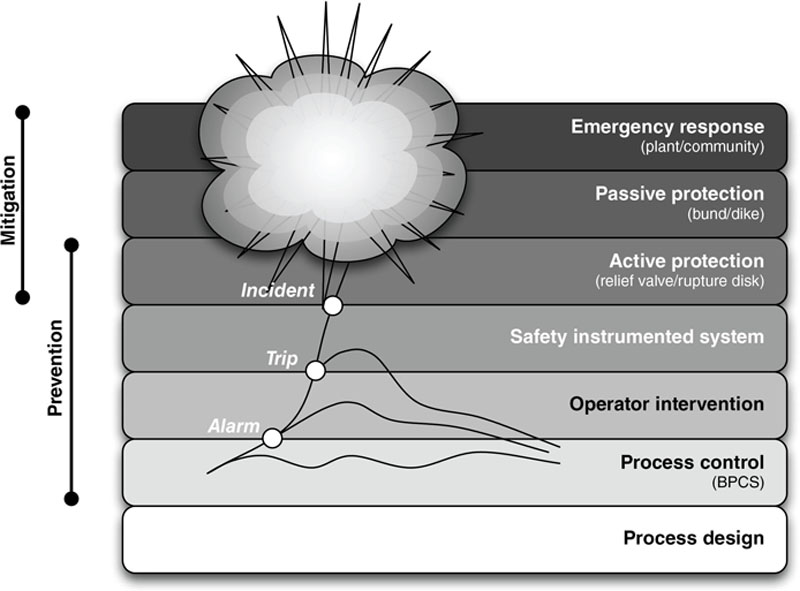
Figure 4.12 Layers of protection in plant safety design.
The risks that originate within the SIS relating to cyber incidents are twofold. First, since the system is responsible for bringing a plant to a safe condition once it is determined to be outside normal operational limits, the prevention of the SIS from properly performing its control functions can allow the plant to transition into a dangerous state that could result in operational disruptions, environmental impact, occupational safety, and mechanical damage. In other words, simple denial-of-service (DoS) attacks can translate into significant risk from a cyber event.
On the other side, since the SIS operationally overrides the BPCS and its ability to control the plant, the SIS can also be used maliciously to cause unintentional equipment or plant shutdowns, which can also result in similar consequences to a service denial attack. In other words, an attacker that gains control of an SIS can effectively control the final operation of the facility.
In both cases, the need to isolate the SIS to the greatest extent possible from other basic control assets, as well as eliminate as many potential threat vectors as possible, is a reasonable approach to improving cyber security resilience. SIS programming, though performing in a similar manner to controller programming previously discussed, is not typically allowed in operational mode. This means that highly authorized applications like SIS programming tools and SIS engineering workstations can be removed from ICS networks until they are required. SIS systems must be tested on a periodic basis to guarantee their operation. This provides a good time to also perform basic cyber security assessments, including patching and access control reviews in order to make sure that the safety AND security of the SIS remains at the original design levels.
The smart grid
Smart grid operations consist of several overlapping functions, intercommunicating and interacting with each other. Many of these functions are built using the ICS assets, protocols, and controls discussed so far, making the smart grid a nexus of many industrial networks. This can be problematic, because the smart grid is complex and highly interconnected. It is not the convergence of a few systems, but of many including customer information systems, billing systems, demand response systems, meter data management systems, and distribution management systems, distribution SCADA and transmission SCADA, protection systems, substation automation systems, distributed measurement (synchrophasors), and many more. Most of these systems interconnect and intercommunicate with many others. For example, customer information systems communicate with distribution management systems, load management systems, customer service systems, and the advanced metering infrastructure (AMI).
The AMI Headend in turn feeds local distribution and metering, as shown in Figure 4.13. The AMI Headend will typically connect to large numbers of smart meters, serving a neighborhood or urban district, which in turn connect to home or business networks, and often to home energy management systems (HEMS), which provide end-user monitoring and control of energy usage.
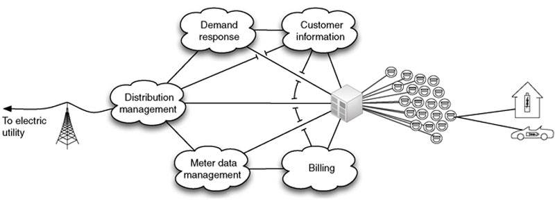
Figure 4.13 Components of a typical smart grid deployment.
Each system in a smart grid serves specific functions that map to different stakeholders, including bulk energy generation, service providers, operations, customers, transmission, and distribution. For example, the customer information system is an operations system that supports the business relationship between the utility and the customer, and may connect to both the customer premise (via customer service portals) as well as the utility back-end systems (e.g. corporate CRM). Meter data management systems store data, including usage statistics, energy generation fed back into the grid, smart meter device logs, and other meter information, from the smart meter. Demand response systems connect to distribution management systems and customer information systems as well as the AMI Headend to manage system load based on consumer demand and other factors.12
Smart grid deployments are broad and widely distributed, consisting of remote generation facilities and microgrids, multiple transmission substations, and so on, all the way to the end user. In metering alone, multiple AMI Headends may be deployed, each of which may interconnect via a mesh network (where all Headends connect to all other Headends) or hierarchical network (where multiple Headends aggregate back to a common Headend), and may support hundreds of thousands or even millions of meters. All of this represents a very large and distributed network of intelligent end nodes (smart meters) that ultimately connect back to energy transmission and distribution,13 as well as to automation and SCADA systems used for transmission and distribution. The benefits of this allow for intelligent command and control of energy usage, distribution, and billing.14 The disadvantage of such a system is that the same end-to-end command and control pathways could be exploited to attack one, any, or all of the connected systems.
There are many threat vectors and threat targets in the smart grid—in fact any one of the many systems touched on could be a target. Almost any target can also be thought of as a vector to an additional target or targets because of the interconnectedness of the smart grid. For example, considering the Advanced Metering Infrastructure, some specific threats include the following:
• Bill manipulation/energy theft—An attack initiated by an energy consumer with the goal of manipulating billing information to obtain free energy.15
• Unauthorized access from customer end point—Use of an intelligent AMI end node (a smart meter or other connected device) to gain unauthorized access to the AMI communications network.16
• Interference with utility telecommunications—Use of unauthorized access to exploit AMI system interconnections in order to penetrate the bulk electric generation, transmission, and distribution system.17
• Mass load manipulation—The use of mass command and control to manipulate bulk power use, with the goal of adversely affecting the bulk electric grid.18
• Denial of service—Using intelligent nodes to communicate to other nodes in a storm condition, with the goal of saturating communications channels and preventing the AMI from functioning as designed.
The AMI is a good example of a probable threat target due to its accessibility with meters accessible from the home, often with wireless or infrared interfaces that can be boosted, allowing for covert access. The AMI is also used by many smart grid systems. Almost all end nodes, business systems, operational systems, and distributed control systems connect to (or through) the Headend, or utilize information provided by the Headend. Compromise of the AMI Headend would therefore provide a vector of attack to many systems. If any other connected system were compromised, the next hop would likely be to the Headend. All inbound and outbound communications at the Headend should be carefully monitored and controlled (see Chapter 9, “Establishing Zones and Conduits”).
This is a very high-level overview of the smart grid. If more detail is required, please refer to “Applied Cyber Security and the Smart Grid.”
Network architectures
The ICSs and operations discussed so far are typically limited to specific areas of a larger network design, which at a very high level consist of business networks, production networks, and control networks, as shown in Figure 4.14.
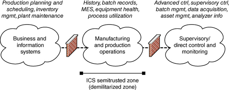
Figure 4.14 Functional demarcation of industrial networks.
Nothing is simple—in reality, industrial networks consist of multiple networks, and they are rarely so easily and neatly organized as in Figure 4.14. This is discussed in detail in Chapter 5, “Industrial Network Design and Architecture.” It is enough to know for now that the ICSs and operations being discussed represent a unique network, with unique design requirements and capabilities.
Summary
Industrial networks operate differently from business networks and use specialized devices including PLCs, RTUs, IEDs, HMIs, application servers, engineering workstations, supervisory management workstations, data historians, and business information consoles or dashboards. These devices utilize specialized protocols to provide the automation of control loops, which in turn make up larger industrial control processes. These automated control processes are managed and supervised by operators and managers within both ICS and business network areas, which requires the sharing of information between two disparate systems with different security requirements.
This is exemplified in the smart grid, which shares information between multiple disparate systems, again across different networks each of which has its own security requirements. Unlike traditional industrial network systems, the smart grid represents a massive network with potentially hundreds of millions of intelligent nodes, all of which communicate back to energy providers, and residences, businesses, and industrial facilities all consuming power from the grid.
By understanding the assets, architectures, topologies, processes, and operations of industrial systems and smart grids, it is possible to examine them and perform a security assessment in order to identify prevalent threat vectors, or paths of entry that a malicious actor could use to exploit the industrial network and the manufacturing process under its control.
..................Content has been hidden....................
You can't read the all page of ebook, please click here login for view all page.