Chapter 5
Industrial Network Design and Architecture
Abstract
The move from proprietary communications networks to more open networks means that, in order to design an industrial network for robust and reliable operation, you must first understand the basic network architecture and design principles of Ethernet and the Internet Protocol (IP). However, because of the unique nature of industrial networks, these principles must first be adapted to support industrial control and automation.
Keywords
Ethernet
TCP
IP
Segmentation
OSI model
Principle of least route
Network performance
Information in this chapter
• Introduction to Industrial Networking
• Common Topologies
• Network Segmentation
• Network Services
• Wireless Networks
• Remote Access
• Performance Considerations
• Safety Instrumented Systems
• Special Considerations
It is important to understand the similarities and differences of typical enterprise or business networks before we get too involved in securing industrial networks. This requires an understanding of how industrial control systems work, as explained previously in Chapter 4, “Introduction to Industrial Control Systems and Operations,” because portions of these networks have been designed around specific criteria relating to how an ICS must operate. This includes not only host-to-host network communications utilizing familiar IT technologies like remote procedure calls (RPC), but also support for legacy fieldbus protocols and vendor-specific protocols that are unlike those seen on business networks. Chapter 6, “Industrial Network Protocols” provides a closer look at these technologies and how many have evolved from original serial-based point-to-point communications to today’s high-speed switched and routed network methods. There are many functions to be served in an industrial network in addition to the control system, along with consideration for many distinct network areas. For example, each controller, and each process that is subordinate to it, is a network consisting of control devices, human–machine interfaces (HMIs) and possibly I/O modules. The supervisory components that oversee these basic control systems are interconnected via a network of specialized embedded systems, workstations, and various types of servers. Many supervisory networks may constitute a larger plant network. In addition, the business network cannot be forsaken here. While not an industrial network, per se, the business network contains systems that indirectly impact industrial systems.
Each area, depending upon its function, capacity, system vendor, and owner/operator will have its own topologies, performance considerations, remote access requirements, and network services. These must all be taken into account when considering one of the most important security design considerations—network segmentation. Network segmentation helps make each network area more manageable and secure, and is a simple but effective weapon in the cyber security arsenal.
Introduction to industrial networking
In this book, an “industrial network” is any network that supports the interconnectivity of and communication between devices that make up or support an ICS. These types of ICS networks may be local-area switched networks as common with distributed control system (DCS) architectures, or wide-area routed networks more typical of supervisory control and data acquisition (SCADA) architectures. Everyone should be familiar with networking to some degree (if not, this book should probably not be read before reading several others on basic network technology and design). The vast majority of information on the subject is relevant to business networks—primarily Ethernet and IP-based networks using the TCP transport that are designed (with some departmental separation and access control) primarily around information sharing and collaborative workflow. The business network is highly interconnected, with ubiquitous wireless connectivity options, and are extremely dynamic in nature due to an abundance of host-, server-, and cloud-based applications and services, all of which are being used by a large number of staff, supporting a diversified number of business functions. There is typically a network interface in every cubicle (or access to a wireless infrastructure), and often high degrees of remote access via virtual private networks (VPN), collaboration with both internal and external parties, and Internet-facing web, e-mail, and business-to-business (B2B) services. Internet connectivity from a business network is a necessity, as is serving information from the business to the Internet. In terms of cyber security, the business network is concerned with protecting the confidentiality, integrity, and availability (in that order) of information as it is transmitted from source generation to central storage and back to destination usage.
An industrial network is not much different technologically—most are Ethernet and IP based, and consist of both wired and wireless connectivity (there are certainly still areas of legacy serial connectivity using RS-232/422/485 as well). The similarities end there. In an industrial network the availability of data is often prioritized over data integrity and confidentiality. As a result, there is a greater use of real-time protocols, UDP transport, and fault-tolerant networks interconnecting endpoints and servers. Bandwidth and latency in industrial networks are extremely important, because the applications and protocols in use support real-time operations that depend on deterministic communication often with precise timing requirements. Unfortunately, as more industrial systems migrate to Ethernet and IP, ubiquitous connectivity can become an unwanted side effect that introduces significant security risk unless proper design considerations are taken.
Table 5.1 addresses some of the many differences between typical business and industrial networks.
Table 5.1
Differences in Industrial Network Architectures by Function
| Function | Industrial Network (control and process areas) | Industrial Network (supervisory areas) | Business Network |
| Real-time operation | Critical | High | Best effort |
| Reliability/Resiliency | Critical | High | Best effort |
| Bandwidth Sessions Latency | Low Few, explicitly defined Low, Consistent | Medium Few Low, consistent | High Many N/A, retransmissions are acceptable |
| Network | Serial, Ethernet | Ethernet | Ethernet |
| Protocols | Real-time, Proprietary | Near real-time, Open | Non real-time, Open |
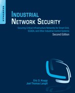
Note that these differences dictate network design in many cases. The requirement for high reliability and resiliency dictates the use of ring or mesh network topologies, while the need for real-time operation and low latency requires a design that minimizes switching and routing hops or may dictate purpose-built network appliances. Both of these requirements may result in a vendor requiring the use of specific networking equipment to support the necessary configuration and customization necessary to accomplish the required functionality. The use of specific protocols also drives design, where systems dependent solely upon a given protocol must support that protocol (e.g. serial network buses).
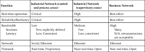
The network shown in Figure 5.1 illustrates how the needs of a control system can influence design (redundancy will not be shown on most drawings for simplicity and clarity). While on the surface the connectivity seems straightforward (many devices connected to Layer 2 or Layer 3 Ethernet devices, in a star topology), when taking into account the five primary communication flows that are required, represented as TCP Session 1 through 5 in Figure 5.1, it becomes obvious how logical information flow maps to physical design. In Figure 5.2, we see how these five sessions require a total of 20 paths that must be traversed. It is therefore necessary to minimize latency wherever possible to maintain real-time and deterministic communication. This means that Ethernet “switching” should be used where possible, reserving Ethernet “routing” for instances where the communication must traverse a functional boundary. This concept, represented in Figure 5.1 and 5.2 as subnets, is important when thinking about network segmentation and the establishment of security zones (see Chapter 9, “Establishing Zones and Conduits). It becomes even more obvious that the selection of Ethernet “firewalls” deployed low in the architectural hierarchy must be designed for industrial networks in order to not impact network performance. One common method of accomplishing this is through the use of “transparent” or “bridged” mode configurations that do not require any IP routing to occur as the data traverses the firewall.
Figure 5.1 Communication flow represented as sessions.
Figure 5.2 Communication flow represented as connections.
Figures 5.1 and 5.2 illustrate a common design utilizing Ethernet switches for low-latency connectivity of real-time systems, such as data concentrators and controllers, and a separate router (typically implemented as a Layer 3 switch) to provide connectivity between the multiple subnets. Note that in this design, the total end-to-end latency from the HMI client to the controller would be relatively high—consisting of 11 total switch hops and 3 router hops. An optimized design, represented in Figure 5.3, would replace the router with a Layer 3 switch (an Ethernet switch capable of performing routing functions2). Layer 3 switches provide significantly improved performance, and by replacing separate Layer 2 and Layer 3 devices with a single device, several hops are eliminated.
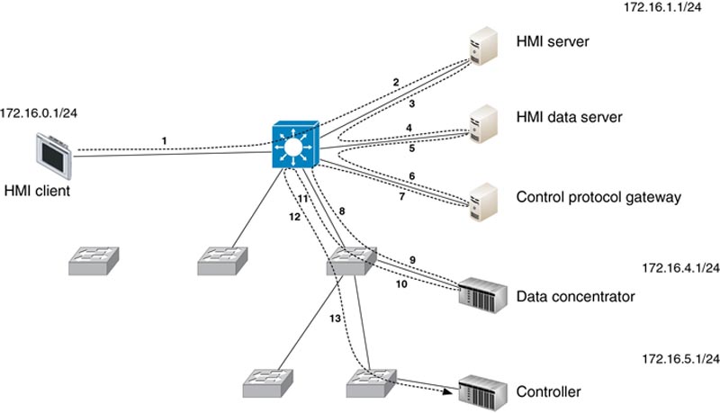
Figure 5.3 Optimized Ethernet network design.
In Figure 5.4, a design typical of one vendor’s systems has been provided. Redundancy is provided here by connecting systems to two separate Ethernet connections. While Figure 5.4 shows a very simple redundant network, more sophisticated networks can be deployed in this manner as well. The use of spanning tree protocol will eliminate loops (in a switched environment) and dynamic routing protocols will enable multipath designs in a routed environment. In more sophisticated designs, redundant switching and routing protocols, such as VSRP and VRRP, enable the use of multiple switches in high-availability, redundant configurations.
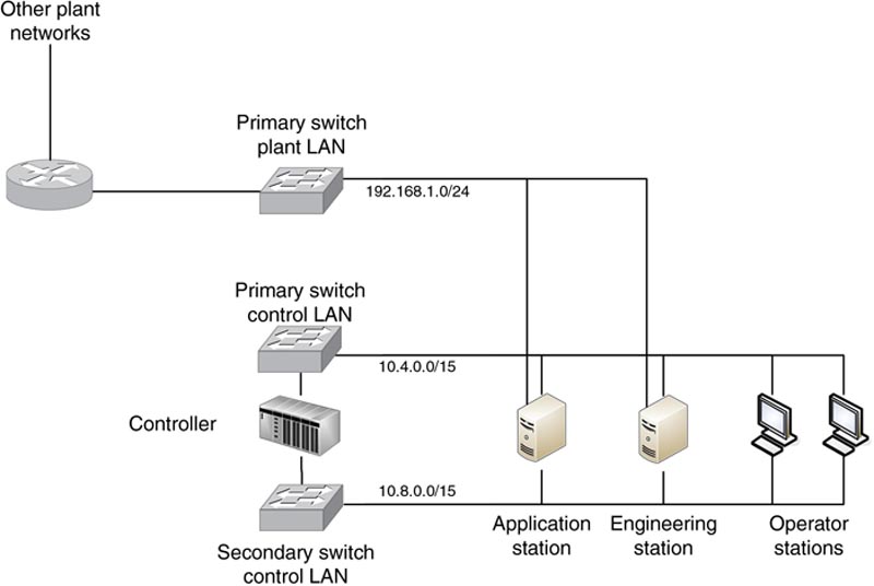
Figure 5.4 Redundant Ethernet in a vendor reference architecture.
As we get lower into the control environment, functionality becomes more specialized, utilizing a variety of open and/or proprietary protocols, in either their native form or adapted to operate over Ethernet. Figure 5.5 illustrates a common fieldbus network based on FOUNDATION Fieldbus using serial two-wire connectivity, and reliant upon taps (known as couplers) and bus terminations. Many fieldbus networks are similar, including PROFIBUS-PA, ControlNet, and DeviceNet.
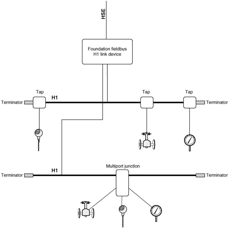
Figure 5.5 FOUNDATION Fieldbus H1 network topology.
It should be evident by now that specific areas of an industrial network have unique design requirements, and utilize specific topologies. It may be helpful at this point to fully understand some of the topologies that are used before looking at how this affects network segmentation.
Common topologies
Industrial networks are typically distributed in nature and vary considerably in all aspects, including the link layer characteristics, network protocols used, and topology. In business environments, Ethernet and IP networks are ubiquitous, and may be implemented in any number of topologies—including star, tree, and even full-mesh topologies (though mesh technologies tend to be only for the uplinks between network devices and not between endpoints and their network access devices). Like in a business, ICS networks may utilize various topologies as well. Unlike business network topologies, those deployed to support industrial systems are also likely to use bus and ring topologies in addition to star, tree, and mesh topologies. This is because, while these topologies have fallen out of favor in business (due to cost, performance, and other considerations), they are often necessary within ICS.
Topologies, such as rings, easily support the necessary redundancy commonly required in industrial networks. A bus topology represents a shared message transmission domain, where many nodes are competing for a finite amount of bandwidth, and relying on traffic coordination or synchronous communication to provide best-effort connectivity. Many ICS architectures are based on underlying technologies like publish-subscribe and token-rings encapsulated in UDP packets well suited for bus technologies. In modern business networks however, this is impractical—switched Ethernet provides a dedicated Ethernet segment with associated guaranteed “first-hop” bandwidth to every node, and has become a commodity, making star topologies extremely common. Likewise, ring topologies (which promise redundant paths for greater reliability) have fallen out of favor with enterprises because full mesh topologies are relatively inexpensive and highly effective (essentially, each node is given two dedicated Ethernet connections to each other node, typically between core network infrastructure devices and/or business-critical servers). In industrial networks, it is more common for the access switches to be connected in a ring configuration while a star topology is used to connect to end devices.
There is still a strong need for both bus and ring topologies in industrial networks depending upon the specific type of control process that is in operation and the specific protocols that are used, as shown in Figure 5.6. In industrial environments that depend on wired communication for reliability, it can be cost prohibitive to implement mesh topologies over traditional bus and ring configurations. Mesh networks have become the de facto standard for wireless industrial networks. For example, an automated control process to sanitize water may use a bus topology with the PROFIBUS-PA protocol, while another control process may use Modbus/TCP in a ring topology to control pumping or filtration systems. As we move farther away (“up the architecture”) from the process and closer to the business network, “typical” IT designs become more prevalent, to the point where many plant networks are designed similarly to corporate data centers, with meshed core switches and routers supporting switched access to smaller workgroup switches.
• Bus topologies are linear, and often used to support either serially connected devices, or multiple devices connected to a common bus via taps. Bus topologies often require that the bus network be terminated at either end by a terminator used to prevent signal reflections. In a bus topology, the resources of the network are shared among all of the connected nodes, making bus networks inexpensive but also limited in performance and reliability. The number of devices connected to a single bus segment is relatively small for this reason.
• Mesh topologies are common for the connectivity of critical devices that require maximum performance and uptime, such as core Ethernet network devices like switches and routers, or critical servers. Because many paths exist, the loss of one connection—or even the failure of a device—does not (necessarily) degrade the performance of the network.
• Wireless Mesh topologies are logically similar to wired mesh topologies, only using wireless signaling to interconnect compatible devices with all other compatible devices. Unlike wired meshes where the physical cabling dictates the available network paths, wireless meshes rely on provisioning to control information flow.
• Star Topologies are point-to-multipoint networks where a centralized network resource supports many nodes or devices. This is most easily illustrated with a standard Ethernet switch that provides individual connections to endpoints or other switches that can also be connected to additional endpoints.
• Branch or Tree Topologies are hierarchically connected topologies where a single topology (typically a bus, representing the “trunk”) supports additional topologies (typically bus or star topologies, representing the “branches”). One practical example of this is the “chicken foot” topology used in FOUNDATION Fieldbus H1 deployments where a bus is used to interconnect several junction boxes or “couplers,” which then allows a star connection to multiple field devices.
• Ring Topologies are, as the name implies, circular, with each node connected serially, but with the final node connected back to the first node, rather than terminating the network at either end. This topology can cover endpoints, but is more commonly used to interconnect network access switches.
• Multihoming or Dual-Homing describes the connection of a single node to two or more networks. Dual homing can be used for redundancy (as illustrated in Figure 5.4), to essentially provide two networks over which a single device can communicate. Dual-homing has also been used as a method of making resources assessable to multiple zones (as illustrated in Figure 5.7), but this is not recommended. In the case of a dual-homed connection between a plant zone and a business zone, any successful break of the dual-homed server would provide a bridge between the two zones, fully exposing the plant zone to the outside world.
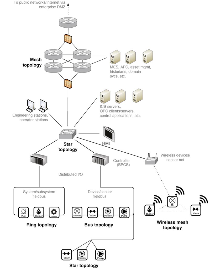
Figure 5.6 Common network topologies as used in industrial networks.
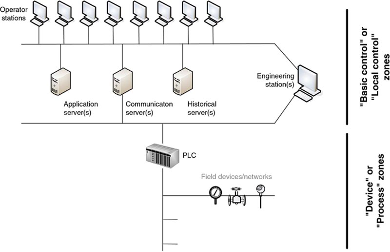
Figure 5.7 Dual-homing used in a vendor reference architecture.
The specific topology and network design can have a significant impact on the security and reliability of a particular network. Network topology will also impact your ability to effectively segment the network, and to control network traffic flow—ultimately impacting your ability to define security zones and to enforce security communication channels via conduits (see Chapter 9, “Establishing Zones and Conduits”). Implementing router access control lists (ACLs), intrusion prevention systems, and application firewalls between two zones can add significant security. If there are dual-homed devices between these two zones, it is possible for an attacker to bypass these security controls altogether, eliminating their value. It is therefore necessary to understand topologies and network designs from the perspective of network segmentation
Network segmentation
Segmentation is important for many reasons, including network performance considerations and cyber security, and so on. The concept of network segmentation was originally developed as a means to limit the broadcast domain of an Ethernet network that was designed at that time around 10 MB connections typically using either a “hub” (10BaseT) or a shared “trunk” (10Base2) as an access medium. Segmentation typically occurs at Layer 3 (the network layer) by a network device providing routing functions (i.e. traditional routers, layer 3 switches, firewalls, etc.). Among other functions, the router blocks broadcasts, enabling a large flat Ethernet network to be broken up into discrete Ethernet segments; each segment having fewer nodes, and therefore fewer broadcasts and less contention. Networks became larger as switched Ethernet technology became commoditized, and the capabilities of network processing increased, providing an alternative method for segmentation. This relatively new development allowed broadcasts to be contained at Layer 2 using virtual LANs (VLANs), which utilize a tag in the Ethernet header to establish a VLAN ID (802.1Q). VLANs enable compatible Ethernet switches to forward or deny traffic (including broadcasts) based upon either the 802.1Q tag or the port’s VLAN ID (PVID). To communicate between VLANs, traffic would need to be explicitly routed between VLANs at Layer 3, using a routing device. Essentially, each VLAN behaved as if it were connected to a dedicated subinterface on the router, only the segmentation occurred at Layer 2, separating the function from the main physical router interface. This meant that VLANs could segment traffic much more flexibly, and much more cost effectively as it minimized the amount of routers that needed to be deployed
Today, there are Layer 3 switches that combine the benefits of a VLAN switch with the added control of a Layer 3 router, making VLANs much easier to implement and maintain. This book will not go into the specifics of VLAN design since there are numerous resources available on this subject if further detail is needed. In this book, it is enough to know the basics of what VLANs are and how they function for the purposes of industrial network design and security. VLANs are an important tool, and it is highly recommended that the reader pursue the topic further and become expert in VLAN behavior, design, and implementation.
How does segmentation apply to industrial networks and to industrial cyber security? As with all networks, industrial networks vary considerably. It has already been discussed how there are many obvious and clearly delineated functions—for example, “business systems” and “plant systems”—as well as specific network topologies, system functions, protocols used, and other considerations that will dictate where a network must be segmented and/or segregated.
Network segmentation allows us to enforce these demarcations by taking larger networks and splitting them up into smaller, more manageable networks, and then utilizing additional security controls to prevent unauthorized communications between these networks. Another way to think of this is as the division of endpoints across distinct networks. For example, ICS servers, controllers, and process-connected devices belong in an “industrial” network, and the corporate web server and enterprise resource planning (ERP) systems in the “business” network. Segmentation, therefore, provides an inherent degree of access control at each demarcation point.
Network segmentation should be used to support zone segmentation whenever possible (see Note at the start of this chapter on network and zone segmentation). Some of the network areas that are candidates for segmentation in support of security zones include the following:
• Public networks like the Internet
• Business networks
• Operations networks
• Plant control networks
• Supervisory control networks (ICS servers, engineering workstations, and HMIs)
• Basic or local control networks (controllers, programmable logic controllers (PLCs), remote terminal units (RTUs), field devices, intelligent electronic devices (IEDs), and subsystems)
• Process networks (device networks, analyzer networks, equipment monitoring networks and automation systems)
• Safety networks (safety instrumented systems (SIS) and devices).
Network segmentation results in hierarchical networks, such that communication between two networks might require traversal of several networks. Using Figure 5.8 as an example, to get from process network B1a to process network B2a, traffic would need to communicate through control network B1, supervisory control network B, and control network B2. This has only been shown for illustrative purposes, as it is unlikely there would be any traffic flow between process networks (in the form of peer-to-peer communications), which is why they were segmented in the first place. Note that we have specifically omitted the devices between networks that would form the basis of this segmentation as this will be covered later. Also note that just because a segmented network architecture supports communication flows between segments, it does not mean that this traffic should be allowed between segments. In the previous example, traffic flow should not be allowed between process networks.
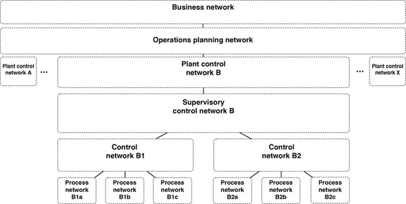
Figure 5.8 A conceptual representation of network segmentation in industrial systems.
Depending upon how the network infrastructure is configured, the division of the network can be absolute, conditional, bidirectional, or unidirectional, as shown in Table 5.2.
Table 5.2
Types of Communication Flow Control
| Absolute | No communication is allowed (i.e. all traffic is blocked in both directions). |
| Conditional | Only explicitly defined traffic is allowed (e.g. via Access Control Lists, filters, etc.). |
| Bidirectional | Traffic is allowed in both directions. Conditions may be enforced in both directions. |
| Unidirectional | Traffic is only allowed in one direction (e.g. via a data diode or unidirectional gateway). |
Higher layer segmentation
While network segmentation is traditionally enforced at Layer 2 (VLANs) or Layer 3 (subnets), the concepts of segmentation—the containment of certain network activities—can be implemented at essentially any layer of the OSI model, often to great effect. For example, by limiting sessions and applications at OSI Layers 4–7 instead of Layers 2–3, it becomes possible to isolate certain communications between carefully defined groups of devices, while allowing other communications to operate more freely. This is defined in Table 5.3.
Table 5.3
Types of Segmentation
| Method | Description | Security Considerations |
| Physical Layer Segmentation | Refers to separation of two networks at the physical layer, meaning that there is a change or disruption in the physical transmission medium that prevents data from traversing from one network to another. An example could be as simple as a disconnected phone cable to a modem or a data diode to block wired transmission, a faraday cage or jammer to isolate wireless signals, etc. The mythical “air gap” is a physical layer segmentation method. Note that the term “physical layer segmentation” should not be confused with “physical segmentation,” as defined below under “Physical vs. Logical Segmentation.” | Can be physically bypassed, via “sneaker net” attacks. In many cases, the excessively restrictive nature of the control motivates end users to bypass security by carrying data on thumb drives or other portable removable media, introducing new attack vectors that may not have controls in place. |
| Data Link Layer Segmentation | Occurs at Layer 2, and as discussed earlier, it is typically performed using Virtual Local Area Networks, or VLANs. Network switches are used to separate systems, and VLANs are used to limit their broadcast domains. VLANs therefore cannot communicate with other VLANs without traversing at least one Layer 3 hop to do so (when trunks are used), or by physically connecting VLAN access ports (when untagged access ports are used). The use of VLANs provides easy and efficient segmentation. If inter-VLAN communication is only allowed via a Layer 3 device, VLANs can also enforce some security by implementing segregation via Access Control Lists (ACLs) on the intermediary router(s). Newer Layer 2 switches provide the capability to implement ACLs at the port level as traffic enters the switch, allowing options to help improve VLAN security since this ACL is applied to all VLANs on a given port. | Because VLANs are easy to implement, they are commonly used for network segmentation, which in turn will minimize the impact of many Ethernet issues and attacks, such as floods and storms. However, VLANs are also the least secure method of segmentation. Improperly configured networks are susceptible to VLAN Hopping attacks, easily allowing an attacker to move between VLANs. See “VLAN Vulnerabilities,” in this chapter. |
| Network Layer Segmentation | Occurs at Layer 3, and is performed by a network router, a network switch with Layer 3 capabilities, or a firewall. For any protocols utilizing the Internet Protocol (IP)—including industrial protocols that are encapsulated over TCP/IP or UDP/IP—routing provides good network layer segmentation as well as strong security through the use of router ACLs, IGMP for multicast control, etc. However, IP routing requires careful IP addressing. The network must be appropriately separated into address subnets, with each device and gateway interface appropriately configured. Network firewalls can also filter traffic at the network layer to enforce network segregation. | Most Layer 3 switches and routers support access control lists (ACLs) that can further strengthen access controls between networks. Layer 3 network segmentation will help to minimize the attack surface of network-layer attacks. In order to protect against higher-layer attacks such as session hijacking, application attacks, etc. “extended” ACLs must be deployed that can restrict on communication port and IP addresses. This reduces the attack surface to only those allowed applications when configured using a “least privilege” philosophy. |
| Layer 4–7 Segmentation | Occurs at Layers 4–7, and includes means of controlling network traffic carried over IP (i.e. above the network layer). This is important because most industrial protocols have evolved for use over IP, but are often still largely self-contained—meaning that functions such as device identity and session validation occur within the IP packet payload. For example, two devices with the IP addresses of 10.1.1.10/24 and 10.1.1.20/24 are in the same network, and should be able to communicate over that network according to the rules of TCP/IP. However, if both are slave or client devices in an ICS, they should never communicate directly to each other. By “segregating” the network based on information contained within the application payload rather than solely on the IP headers, these two devices can be prevented from communicating. This can be performed using variable-length subnet masking (VLSM) or “classless” addressing techniques. | This is a powerful method of segmentation because it offers granular control over network traffic. In the context of industrial network security, application layer “content filtering” is able to enforce segregation based upon specific industrial protocol use cases. Application layer segregation is typically performed by a “next generation firewall” or “application aware IPS,” both of which are terms for a device that performs deep packet inspection (DPI) to examine and filter upon the full contents of a packet’s application payload. Filtering can be very broad, limiting certain protocol traffic from one IP address to another over a given port, or very granular, limiting certain protocols to performing specific functions between pre-defined devices—for example, only allowing a specific controller to write values that are within a certain range to specific, explicitly defined outputs. |
One point worth mentioning is that the more security that you can deploy at the various layers of the OSI model, the more resilient your architecture will be to attack. The attack surface within the communication stack typically decreases as you move “down” the stack. This is one reason why data diodes and unidirectional gateways provide one of the highest levels of segregation control because they are implemented at the Physical layer. Another example is that by implementing static MAC address tables within the Layer 2 switches, communication between devices can be restricted irrespective of any IP addressing (Layer 3) or application (Layers 4–7) vulnerabilities that may compromise the network. MAC addresses and IP addresses can both be discovered and spoofed, and application traffic can be captured, altered and replayed. So at what layer should security be implemented? Risk and vulnerability assessments should help answer this dilemma. The first step is to focus on protecting areas that represent the greatest risk first, which is usually determined by those areas that possess the greatest impact and not necessarily those that contain the most vulnerabilities. Subsequent assessments will then indicate if additional layers of security are required to provide additional layers of protection and offer greater resilience to other cyber weaknesses.
VLAN segmentation is common on networks where performance is critical as it imposes minimal performance overhead and is relatively easy to manage. It should be noted that VLANs are not a security control. VLANs can be circumvented, and can allow an attacker to pivot between network segments (see “VLAN Vulnerabilities,” in this chapter). More sophisticated controls should be considered in areas where security is more important than network performance.
The relative benefits of various network segmentation methods are summarized in Table 5.4.
Table 5.4
Characteristics of Segmentation
| Segmentation/Segregation | Provided By | Management | Performance | Network Security | ICS Protocol Support | OT Applicability |
| Physical Layer | Air Gap Data Diode | None | Good | Absolute | N/A | High |
| DataLink Layer | VLAN | Moderate | Good | Very Broad | High | High |
| Network Layer | Layer 2 Switch (via VLAN interfaces only) Layer 3 Switch Router | Low | Moderate | Broad | High | High |
| Session Layer | Firewall IPS Protocol Anomaly Detection | Moderate | Low | Specific | Moderate | Moderate |
| Application Layer | Application Proxy/IPS “Next Generation” Firewall/IPS Content Filter | High | Poor | Very Specific | Low | Low |

In order to realize the benefits of security from an application layer solution shown in Table 5.4, it must be able to recognize and support those applications and protocols used with ICS architectures. At the time of publishing, there are still relatively few devices that provide this support, and the number of applications and protocols included is very small in relation to that observed in a variety of ICS installations. Consideration must always be given to any restrictions in place regarding the installation of third-party or “unqualified” software and controls on ICS components by the ICS vendors. ICS components are subjected to rigorous stability and regression testing to help ensure high levels of performance and availability, and for this reason, ICS vendor recommendations and guidelines should always be given due consideration.
Similarly, the degree to which a network should be segmented requires both consideration and compromise. A highly segmented network (one with more explicitly defined networks and fewer nodes per network) will benefit in terms of performance and manageability.
Physical vs. logical segmentation
It is important to understand the difference between physical and logical segmentation, and is why this has been used in a variety of scenarios throughout this chapter. In the lexicon of network design, physical segmentation refers to the use of two separate physical network devices (both passive and active components) to perform the isolation between networks. For example, Switch 1 would support Network 1, and Switch 2 would support Network 2 with a router managing traffic between the two. In contrast, logical segmentation refers to the use of logical functions within a single network device to achieve essentially the same result. In this example, two different VLANs are used in a single Switch and a trunk connection to a Layer 3 Switch or router is used to control access between the networks.
Physical separation of systems (“air gap” separation) is still widely used in industrial networks when talking about the coexistence of basic process control and safety systems overseeing the same process. Physical-layer controls are still popular in highly critical areas (such as between safety- and non–safety-related levels in a nuclear power generating station) via the use of data diodes and unidirectional gateways. This has led to some confusion between the terms physical segmentation (multiple physical network devices) and the concept of physical-layer separation (isolation at the physical layer).
Proper network segmentation is important for both process and control networks that often utilize UDP multicasts to communicate between process devices with the least amount of latency. Layer 2 network segmentation within a common process may be impossible because it would break up the required multicast domain. The lack of segmentation between unrelated processes could also cause issues because multicasts would then be transmitted between disparate processes, causing unnecessary contention as well as potential security risks. Process networks often segment broadcast domains using VLANs when segmentation is possible, supporting multiple processes from a single Ethernet switch. Each process should utilize a unique VLAN unless open communication between processes is required, and/or communication between services should be limited or disabled at the switch. Communication between control networks and process networks are handled at a higher tier of the overall architecture using Layer 3 switching or routing.
The implementation of additional security controls within a process network can be difficult for the same reason as just explained. This may be of some concern because VLAN segmentation can be bypassed. In larger process networks, or in broadly distributed process networks (where geographically distributed devices make physical network access more difficult to prevent), this can introduce an unacceptable level of risk. This concept is discussed within ISA 62443-3-3 in terms of a relative “Security Level” assigned to each segment or zone. Logical segmentation is only allowed between those segments/zones that require minimal security against cyber threats.
To address this risk
• Implement defense-in-depth security controls at the demarcation points where networks can be segmented. Example: Deploy a network-based security control in the process network, using a transparent firewall or IPS, that can monitor and enforce traffic without blocking multicasts or other expected process control traffic. Implement network security controls immediately upstream of the process network VLAN switch where this is not possible.
• Monitor process network activity. If network controls are deployed, these controls can provide security event logging and alerting to provide security analysts with the needed visibility to the process network. If they are not (or cannot) be deployed, consider deploying IDS devices on mirrored or spanned switch interfaces, so that the same degree of monitoring can occur out of band.
Attention must be given to physical and environmental conditions that exist within a production environment before any decision is made on a particular security control deployed within an industrial network. Devices must typically be able to operate over extended temperature ranges and even hazardous environments—requirements not typically of standard security technologies deployed in business networks. It is not acceptable to increase security at the price of decreased availability and loss of production when securing industrial networks and systems.
Network services
Network services, such as identity and access management (IAM), directory services, domain services, and others are required to ensure that all industrial zones have a baseline of access control in place. While these systems are most likely already in place within the business network, utilizing them within industrial networks can introduce risk.
Domain servers and other identity- and access-control systems should be maintained separately for the industrial network. This is counter-intuitive to most IT security professionals who recognize the value of centralized network services. However, the risk that a domain controller in the business zone could be compromised is much higher than the risk to a domain controller that is isolated within the plant zone. The user credentials of OT managers should therefore not be managed by IAM systems that have been deployed within the business zone. Rather, they should be managed exclusively from within the plant zone. Note that an authoritative source of identity information (e.g. human resource systems) still has value to an industrial system—it is only that the authoritative source needs to reside within that system. Any federation of information into the plant zone from centralized IT services should be very carefully controlled, and no supporting authentication and authorization systems should be allowed to serve both zones. In this way, if servers in the business domain are breached, valid credentials of OT users cannot be compromised, because they reside only within OT-located systems.
As a general rule, when providing for network services in industrial systems, abide by the principle of least route, which states that in purpose-built networks, such as those used for industrial automation, a node should only be given the connectivity necessary to perform its function.3 Any required connectivity should be provided as directly as possible to a given system (see the callout “The Principle of Least Route,” in this chapter). If a critical system needs a specific network service, provide that source locally, and do not share the resource to other systems in unrelated networks (see also, Chapter 9, Establishing Zones and Conduits).
Wireless networks
Wireless networks might be required at almost any point within an industrial network, including plant networks, supervisory networks, process control networks, and field device networks. Wireless networks are bound by the same design principles as wired networks; however, they are more difficult to physically contain because they are bound by the range of the radio wave propagation from an access point rather than by physical cables and network interfaces. This means that any device that is equipped with an appropriate receiver and is within the range of a wireless access point can physically receive wireless signals. Similarly, any device equipped with a suitable transmitter that is within range of an access point can physically transmit wireless signals.
There is no sure way to prevent this physical (wireless) access, as the effective range of the wireless network can easily be extended. While it is possible to block transmissions by using jammers or signal-absorbing materials (such as a Faraday containment), these measures are costly and rarely implemented. For this reason, industrial networks that implement outdoor wireless networks typically conduct thorough radio frequency surveys in order to not only place antennas in optimal locations considering a location’s unique physical obstructions, but also prevent unnecessary transmission of signals into untrusted and unrestricted areas.
Some might argue that the inherent lack of physical containment makes wireless networking a poor fit for industrial networks, as it presents a very broad attack surface. However, as is often the case, there are legitimate use cases where wireless networking makes sense to the process. The existence of such use cases has spurred a rapid growth in wireless industrial networking, led by the use of WirelessHART and OneWireless. WirelessHART is a wireless implementation of the HART Communication Protocol using IEEE 802.15.4 radio and TDMA communication between nodes, while OneWireless is an implementation of ISA 100.11a wireless mesh networking based on IEEE 802.11 a/b/g/n standards and is used to transport common industrial protocols, such as Modbus, HART, OPC, General Client Interface (GCI), and other vendor-specific protocols.
Both systems support mesh networking and use two devices: one to manage connected nodes and communications between nodes, and one to enforce access control and security. A common implementation of WirelessHART is shown in Figure 5.9 illustrating how the Network Manager and Security Manager are connected via wired Ethernet to the WirelessHART gateway. One or more access points also connect to the gateway with each wireless device acting as a router capable of forwarding traffic from other devices, building out the wireless network.
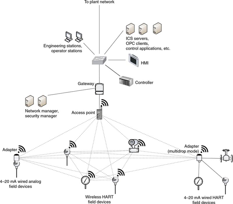
Figure 5.9 A wireless HART network.
One important consideration in deploying wireless networks in ICS architectures is that they are commonly used to support remote, difficult, and/or costly connectivity between field devices and basic control components like PLCs and asset management systems. In areas where local power is unavailable, power can be extracted from the same line used for communications (e.g. Power over Ethernet, or PoE), or utilize local batteries. This is an important consideration, as the availability of power directly impacts the availability of the process. In the case of battery power, battery life versus communication speed and update rate must be considered, and typically limits the deployment of wireless field technologies in closed-loop control applications.
Remote access
Remote access is a necessary evil that must be considered when designing a secure industrial network. Remote access serves many needs of an organization. For example, an ICS commissioned in a manufacturing facility will typically include third-party contracts with explicitly defined service requirements, often requiring 24×7 response, with measured response times and guarantees around problem resolutions. The ICS vendor might staff support personnel in multiple time zones around the globe to meet strict service demands, while dictating that remote access be provided to allow technicians to connect to the ICS remotely for diagnostics and problem resolution. Distributed workforces within the company may also pose an issue. If engineers work remotely or from home offices, remote access to engineering systems must also be provided. In some cases (e.g. wind turbines, pipelines, oil and gas production fields) devices may be physically difficult to access, making remote access a functional necessity.
Remote access can introduce multiple attack vectors at the same time. Even if secure remote access methods are used, such as virtual private networks, two-factor authentication, and so on, a node can be compromised remotely, because the underlying infrastructure used with remote access is connected to public, untrusted networks like the Internet.
To address the risks of remote access, all access points should be considered an open attack vector and should only be used when necessary. Strict security controls should be used, including the following:
• Minimize attack vectors. Only provide one path over which remote access may occur when implementing a remote access solution. This allows the single path into and out of the network to be carefully monitored and controlled. If multiple paths are allowed, it is more likely that security controls might be eliminated (due to the added cost of securing multiple paths), or that a specific security control might be overlooked or misconfigured.4
• Follow the principle of “least privilege,” allowing users to only access those systems or devices with which they have a specific need or authority.5
This means that if a user only needs to view data, they should not be provided mechanisms to download and change data.
• To enforce “least privilege,” the network may require further segmentation and segregation to isolate systems that allow remote access from other systems not accessed remotely. Ideally, third parties, such as subcontractors and vendors, should be restricted access to only their devices, which may impact network segregation design, and only allowed to perform those functions they are authorized to perform remotely (e.g. view configuration versus download new configuration and software to devices). This will be explained in greater detail in Chapter 9, “Establishing Zones and Conduits.”6
• Application control may also be required to further limit remote users to only those applications with which they are authorized. Requiring remote users to authenticate directly to a secure application server rather than just using a remote access server (RAS) limits the remote access session to a specific application rather than to the network on which the server resides.7
• Prevent direct access to any system that is considered critical or where the risk to a system outweighs the benefit of remote access. Force remote access through a secure semitrusted or demilitarized zone (DMZ) or proxy so that additional security controls and monitoring can be implemented if remote access is required for these systems.8
• The security policy deployed for an endpoint connecting via remote access should be equal to or better than that of the hosts directly connected to the trusted industrial network. This can be very difficult to enforce, especially with third parties, and is why the preferred approach may be to create a “jump station” that is always used to provide a landing point for the remote user before accessing the final trusted industrial network-connected device. This physically separates the remote user’s local computer and associated resources (removable media, file system, clipboard, etc.) from that computer accessing the industrial network.
• Avoid storing credentials on the remote end of the connection (e.g. the vendor support personnel) that are transmitted and utilized on the most trusted industrial network, even if they are transmitted within encrypted tunnels.
• Procedures should be established and tested that allow for site personnel to terminate and disconnect remote access mechanisms locally in the event of a cyber incident.
• Log everything. Remote access, by its nature, represents an attack vector where only one end of the connection is 100% known and controlled. All remote access attempts, successful or not, should be logged, and all activity performed by remote users during their entire session should be logged. This provides a valuable audit trail for investigators during incident response and disaster recovery efforts. In addition, if security analytics—such as advanced security information and event management systems (SIEMs) or anomaly detection systems—are used, these logs can provide proactive indicators of an attack, and can greatly reduce incident response times, which in turn will minimize losses in the event of an attack.
Performance considerations
When talking about network performance, it is necessary to consider four components: bandwidth, throughput, latency, and jitter.
Latency and jitter
Latency is the amount of time it takes for a packet to traverse a network from its source to destination host. This number is typically represented as a “round-trip” time that includes the initial packet transfer plus the associated acknowledgment or confirmation from the destination once the packet has been received.
Networks consist of a hierarchy of switches, routers, and firewalls interconnected both “horizontally” and “vertically” making it necessary for a packet to “hop” between appliances as it traverses from host to destination (see Figures 5.1 and 5.2). Each network hop will add latency. The deeper into a packet the device reads to make its decision, the more latency will be accrued at each hop. A Layer 2 switch will add less latency than a Layer 3 router, which will add less latency than an application layer firewall. This is a good rule of thumb, but is not always accurate. The adage “you get what you pay for” is true in many cases, and network device performance is one of them. A very complex and sophisticated application layer device can outperform a poorly defined software-based network switch built on underpowered hardware if built with enough CPU and NPU horsepower, or custom-designed high-performance ASICs.
Jitter on the other hand is the “variability” in latency over time as large amounts of data are transmitted across the network. A network introduces zero jitter if the time required transferring data remains consistent over time from packet-to-packet or session-to-session. Jitter can often be more disruptive to real-time communications than latency alone. This is because, if there is a tolerable but consistent delay, the traffic may be buffered in device memory and delivered accurately and with accurate timing—albeit somewhat delayed. This translates into deterministic performance, meaning that the output is consistent for a given input—a desirable feature in real-time ICS architectures. Latency variation means that each packet suffers a different degree of delay. If this variation is severe enough, timing will be lost—an unacceptable condition when transporting data from precision sensors to controls within a precisely tuned automation system.
Bandwidth and throughput
Bandwidth refers to the total amount of data that can be carried from one point to another in a given period of time, typically measured in Megabits per second (Mbps) or Gigabits per second (Gbps). Contention refers to competition between active nodes in a network segment for the use of available bandwidth. Bandwidth is not usually a concern in industrial networks, as most ICS devices require very little bandwidth to operate (often much less than 100 Mbps, across the entire ICS during normal operation), while most Ethernet switches provided 100 Mbps or 1000 Mbps per switch interface. (It is not uncommon for embedded ICS devices like PLCs and RTUs to contain 10 Mbps network interfaces that may require special configuration at the switch level to prevent undesirable network traffic from impacting communication performance.) Industrial network designs must accommodate bursts of event-related data (often in the form of multicast traffic) that can be seen during upsets or disturbances to the manufacturing process. Contention for available bandwidth can still be an issue on heavily populated networks, large flat (Layer 2) networks, or “noisy” networks. Areas to watch out for include links between large VLAN-segmented networks and a centralized switch or router that connects these to upstream networks (e.g. the supervisor control network shown in Figure 5.8 may need to process traffic from all subordinate networks including the individual process networks).
Throughput refers to the volume of data that can flow through a network. Network throughput is impacted by a variety of physical, MAC, network, and application layer factors—including the cabling (or wireless) medium, the presence of interference, the capabilities of network devices, the protocols used, and so on. Throughput is commonly measured in packets per second (pps). The correlation between bandwidth and throughput is dependent on the size of the packet. A device that can transfer data at the full capability of the network interface is considered to support line rate throughput. Some networking hardware may not be able to move packets through the device at line rate even though the rated speed of a fast Ethernet connection might be 100 Mbps. Throughput is an important measurement when real-time networking is a requirement. If the network traffic generated in real-time networks (such as in process and control networks) exceeds the rated throughput of the network infrastructure, packets will be dropped. This will cause added delay in TCP/IP communications since lost packets are retransmitted. In UDP/IP communications (common with broadcast and multicast traffic), lost packets are not immediately transmitted per the UDP standard, but rather retransmitted based on error correction in the application layer. Depending on the applications and protocols used, this could result in communications errors (see Chapter 6, “Industrial Network Protocols”).
Type of service, class of service, and quality of service
Quality of service (QoS) refers to the ability to differentiate and prioritize some traffic over other traffic. For example, prioritizing real-time communications between a PLC and an HMI over less critical communications. Type of service (ToS) and class of service (CoS) provide the mechanisms for identifying the different types of traffic. CoS is identified at Layer 2 using the 802.1p protocol—a subset of the 802.1Q protocol used for VLAN tagging. 802.1p provides a field in the Ethernet frame header that is used to differentiate the service class of the packet, which is then used by supporting network devices to prioritize the transmission of some traffic over other traffic.
Type of service is similar to CoS, in that it identifies traffic in order to apply a quality of service. However, ToS is identified at Layer 3 using the 6-bit ToS field in the IPv4 header.
Both ToS and CoS values are used by QoS mechanisms to shape the overall network traffic. In many network devices, these levels will map to dedicated packet queues, meaning that higher priority traffic will be processed first, which typically means lower latency and less latency variation. Note that QoS will not improve the performance of a network above its baseline capabilities. QoS can ensure that the most important traffic is successfully transmitted in conditions where there is a resource constraint that might prevent the transmission of some traffic in a timely manner (or at all).
Network hops
Every network device that traffic encounters must process that packet, creating varying degrees of latency. Most modern network devices are very high performance, and do not add much, if any, measureable latency. Routers and some security devices that operate at Layers 4–7 may incur measureable amounts of latency. Even low amounts of latency will eventually add up in network designs that use many hops. For example, in Figure 5.2, there are 20 total hops, with three (3) of these processed by a router. In the optimized design, which replaces the router with a Layer 3 switch, there are only 13 hops, and all of them are done at high speed.9 The network design should be optimized wherever possible, because industrial networks are time critical and deterministic in nature.
Network security controls
Network security controls also introduce latency, typically to a greater degree than network switches and routers. This is because, as in switches and routers, every frame of network traffic must be read and parsed to a certain depth, in order to make decisions based upon the information available in Ethernet frame headers, IP packets headers, and payloads. The same rule applies as before—the deeper the inspection, the greater the imposed latency.
The degree of processing required for the analysis of network traffic must also be considered. Typically, when performing deep packet inspection (a technique used in many firewalls and IDS/IPS products), more processing and memory is required. This will increase relative to the depth of the inspection and to the breadth of the analysis, meaning the more sophisticated the inspection, the higher the performance overhead. This is typically not a problem for hardware inspection appliances, as the vendor will typically ensure that this overhead is accommodated by the hardware. However, if a network security appliance is being asked to do more than it has been rated for in its specifications, this could result in errors, such as increased latency, false negatives, or even dropped traffic. Examples include monitoring higher bandwidth than it is rated for, utilizing excessive numbers of active signatures, and monitoring traffic for which preprocessors are not available. This is one reason why the deployment of traditional IT controls like IDS/IPS in OT environments must be carefully reviewed, and “tuned” to contain only the signatures necessary to support the network traffic present (this will also help to reduce false positives). If an industrial network does not have Internet access, then signatures relating to Internet sites (i.e. gaming websites or other business-inappropriate sites) could easily be removed or disabled.
Safety instrumented systems
A safety instrumented system consists of many of the same types of devices as a “regular” ICS—controllers, sensors, actuators, and so on. Functionally, the SIS is intended to detect a potentially hazardous state of operation, and place the system into a “safe state” before that hazardous state can occur. SISs are designed for maximum reliability (even by the already-high standards of automation), and often include redundancy and self-diagnostics to ensure that the SIS is fully functional should a safety event occur. The idea is that the SIS must be available when called upon to perform its safety function. This requirement is measured as a statistical value called the average probability of failure on demand (PFD). This probability is stated as a Safety Integrity Level (SIL) ranging from 1 to 4 (SIL1 has a PDF of <10−1, SIL2 <10−2, SIL3 <10−3, and SIL4 <10−4.)
Ideally, safety systems are built using dedicated controllers known as “logic solvers” to support a specific process. The SIS can either be “interfaced” to the basic process control system (BPCS) components via hardwired connections, or “integrated” via higher-level connectivity that may include a common or shared network. More recent standards and trends allow safety devices to coexist and interoperate with standard BPCS devices in the process network (example: Emerson DeltaV SIS11 and Honeywell Safety Manager12). Some SIS solutions are also available that allow process and safety functions to exist within the same device (example: ABB AC 800M HI13 and Siemens S7-400FH, S7-300F and ET-20014). Some industrial protocols allow safety and basic control messaging to share a common messaging and control infrastructure. This trend introduces new security concerns15. While SIS cannot protect against cyber-attacks directly, they should be able to prevent catastrophe from being caused by a cyber-attack against an industrial process by putting the system into a secure state before the catastrophe can occur.
Entire books have been written solely on the topic of securing SIS. In this book, the advice will be limited and general:
• SIS exists to prevent unsafe conditions. When implementing an SIS, do so in a way that a malicious actor who successfully compromises control and process zones will not be able to also compromise the SIS. Preference should be to keeping the SIS completely segregated from upstream networks (including supervisory networks), and when integration or interfacing is necessary, direct point-to-point connections are recommended.
• Comply with the Principle of Least Privilege when implementing an SIS to minimize the potential vectors that an attacker might take to access the safety systems.
• Consider failures and unsafe states when implementing an SIS that may be the result of a manipulation of the controller, process, protocols, and systems of the industrial network by an attacker.
Special considerations
Industrial control systems are used for a variety of purposes across many industries, and because of this, there will always be special circumstances that need to be considered when designing the industrial networks. The use of specialized wide area networks will grow as businesses become increasingly global. As systems are tuned to specific purposes—such as the advanced metering requirements for the smart grid—specialized networks, such as the advanced metering infrastructure (AMI), will evolve to accommodate them. It is important to give specialized systems their due consideration while continuing to apply the fundamental principles of secure network design.
Wide area connectivity
Long-range, wide area connectivity requirements are common when interconnecting central control rooms to remote plants, microgrids, pipelines, offshore oil platforms, remote wind farms, and other far-reaching locations. Wide area connectivity can be provided by private infrastructure or by leased connectivity from public carriers. The technologies vary widely, as do the transport mediums, which may include satellite, microwave, radio, fiber optic, cellular, and others.
Wide area connectivity should be given the same consideration as any other network connection when designing a secure network. By its nature, the WAN infrastructure is physically accessible to unknown users who could potentially be threat actors, especially at unmanned sites with network connectivity. Access can also be provided through the use of appropriate wireless transmitters and receivers, or by physically splicing or taping cables and wires. These connections should therefore be considered higher risk, and extra measures should be taken to ensure the confidentiality, integrity, and availability of any wide area connection.
When performing risk and vulnerability assessments, make sure that specialized wide area overlay networks are not overlooked. In smart grid applications, distributed phase measurement devices called synchrophasors require precisely synchronized timing, and utilize GPS network timing. The GPS network is a globally accessible network, and researchers have proven that GPS spoofing can result in real-world impact. A study by the University of Texas and Northrup Grumman showed how GPS spoofing was able to manipulate synchrophasor readings and cause a plant to trip.16 In another study by the University of Texas, GPS spoofing was used to alter GPS coordinates to a cruise ship, enabling the researchers to steer the ship off of its intended course.17
As GPS, cellular and similar technologies become increasingly popular for the interconnection of highly distributed remote devices; they will continue to introduce new threat vectors to systems that utilize them.
Smart grid network considerations
One area that deserves special consideration is the smart grid. As mentioned in Chapter 4, “Introduction to Industrial Control Systems and Operations,” the smart grid is an extensive network providing advanced metering and communications capabilities to energy generation, transmission and distribution. It may be specific to the energy industry, yet is also a concern for any other industrial sector that may connect to the smart grid as a client of the electric utility industry.
The smart grid varies widely by deployment, and the topologies and protocols used vary accordingly. There is one primary quality that is consistent across any smart grid deployment, and that is its scale and accessibility. As a distribution system designed to deliver power ubiquitously to industrial facilities, residences, offices, storefronts, and all aspects of urban infrastructure, even small smart grid deployments create large numbers of nodes and network interconnections. These networks can exceed hundreds of thousands to even millions of interconnected devices. The scale of a smart grid requires the use of some mechanism to “tier” or hierarchically distribute the nodes.
Represented in terms of an addressable attack surface, smart grids provide broad and easy access to a network that ultimately interconnects the electric utility transmission and distribution infrastructure to many homes and businesses. Figure 5.10 illustrates the attack surface as being exponentially larger as one radiates outward from core electric power generation through long-distance transmission to regional distribution and the outer reaches of the smart grid.
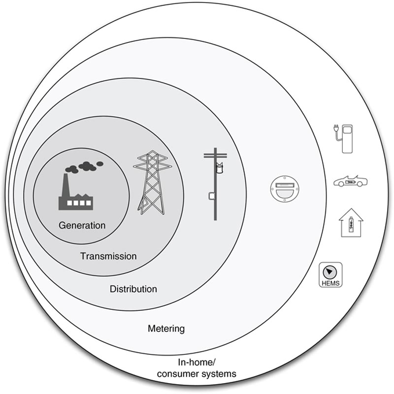
Figure 5.10 The expanding attack surfaces within a smart grid.
Scalability also plays a role in the development of smart grid devices, putting significant cost pressure on the end-node devices (smart meters). Any device deployed at such a large scale needs to be as efficient to build, deploy, operate, and maintain as possible. This business driver is a real concern because of the costs and complexity of providing security assurance and testing throughout the supply, design, and manufacturing stages of smart meter development. As pressures force costs down, there is an increased chance that some physical or network-based vulnerability will find its way into production, and therefore into one of the most easily reachable networks ever built.
Advanced metering infrastructure
Advanced metering infrastructure systems are utilized by electric, water, and gas utilities. AMI is a good example of a specialized industrial network—it has unique characteristics in that it is highly distributed, massively scalable to millions of nodes, uses specialized systems and protocols, and presents a number of new security and privacy considerations. It also operates very similarly to many industrial networks in that it is built of operator-owned devices that function in a (theoretically) closed system. Unlike many industrial networks, which are isolated behind physical security controls, and protected behind multiple layers of network defenses, the metering infrastructure is extremely accessible.
Advanced metering infrastructure architecture consists of smart meters, a communication network, and an AMI server or headend. The smart meter is a digital device consisting of a solid state measuring component for real-time data collection, a microprocessor and local memory to store and transmit measurements, and at least one network interface to communicate to the headend. The headend will typically consist of an AMI server, which is primarily responsible for collection of meter data, and a meter data management system (MDMS), which manages that data and shares it with demand response systems, historians, billing systems, and other business applications. The headend maintains communications with the meters to read data (to measure consumption), push data (to transmit rate information for demand-response systems), and to establish control (for remote disconnects). The headend also intercommunicates with many other systems in the smart grid—transmission and distribution ICS servers, demand response servers, energy management systems (EMS), in home networks, and many others (for more detail on smart grid architecture, please refer to “Applied Cyber Security and the Smart Grid,”).
Some common issues that have already been discussed with regard to other industrial networks become obvious. The specialized devices are essentially computing platforms—they have microprocessors, memory, storage, and can execute code. This means that the system can be exploited, data can be manipulated, and an attack can easily propagate to other interconnected systems. In the United States alone, nearly 65 million smart meters will have been deployed by 201518, with a global estimate of 602.7 million smart meters deployed by 201619. This rapid deployment makes AMI a highly scalable communication network, and in turn a vast attack surface that is comparable to the Internet itself. To further complicate matters, a variety of less common network technologies are used in AMI systems, including Broadband over Power Line (BPL), Power Line Communications (PLC), radio networks (VHF/UHF), and telecommunications (landline, cellular, paging, etc.) networks.
Summary
By understanding how industrial control systems and automation processes function, and by adhering to the basic principles of secure network design, it is possible to accommodate ICSs on modern Ethernet networks. This becomes especially important when considering how industrial protocols operate, which is covered in Chapter 6, “Industrial Network Protocols.”
..................Content has been hidden....................
You can't read the all page of ebook, please click here login for view all page.