Chapter 10
Implementing Security and Access Controls
Abstract
With a properly designed and segmented network, there is still the danger of a targeted cyber-attack. To defend these important networks, it is important to know which endpoint- and network-based cyber security controls are available, and how best to use them.
Keywords
Network Security
Firewall
IDS
IPS
DPI
Anti-virus
Application Whitelisting
Data Diodes
Host IDS
Information in this chapter
• Network Segmentation
• Implementing Network Security Controls
• Implementing Host Security and Access Controls
• How Much Security is Enough?
Once security zones and the associated conduits connecting these zones have been defined (see Chapter 9, “Establishing Zones and Conduits”), they now need to be properly secured according to the Target Security Level identified. A “zone” is nothing but a logical construct without proper network segmentation and access controls. A “zone” represents a logically and often times physically isolated network of systems that, when proper network segmentation and access controls are in place, will by its nature be more difficult to breach from an outside threat agent, and will better contain incidents in the event a breach does occur.
The process of securing zones can be summarized as follows:
1. Map the logical container of the zone against the network architecture, so that there are minimal network paths or communication channels into and out of each zone. This is effectively creating a zone “perimeter” and from this, “entry/exit points” are identified.
2. Make any necessary changes to the network so that the network architecture aligns with the defined zones. For example, if two zones currently coexist within a flat network, segment the network in order to separate the zones.
3. Document the zone for purposes of policy development and enforcement.
4. Document the zone for purposes of security device configuration and monitoring.
5. Document the zone for the purposes of change management.
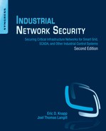
In some instances, such as the one illustrated in Figure 10.1, a single zone may consist of multiple, geographically or otherwise separated groups (e.g. by business function). In these cases, the zone is still considered to be a single zone. If there are any network connections between the two (or more) locations, they should be held to the same security requirements (meaning the use of the same set of controls) as the rest of the zone. That is, there should be no communication across those links that do not originate and terminate within the zone, and if outside communication is required (i.e. a communication that either originates or terminates outside of one of the two zones), it must occur through defined and secure access points (note: this is referring to a general point of access, and not a “wireless access point” or WAP). One common method of interconnecting distributed zones is the use of a dedicated virtual private network (VPN) or other encrypted gateways that provide secure point-to-point communications. A dedicated network connection or fiber cable may be used to interconnect extremely critical zones so that physical separation is maintained.
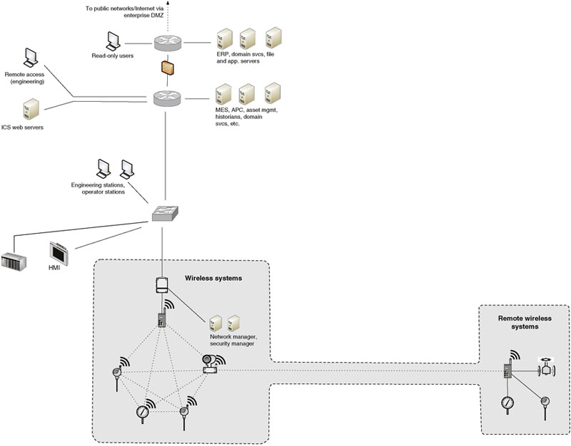
Figure 10.1 A geographically split zone.
The goal is that each zone be isolated as strictly as possible, with as few conduits as possible between that zone and any other directly adjacent (or surrounding) zone. Figure 10.2 shows how, by providing a single access point in and out of a zone, that point can be secured using a perimeter security device, such as a next-generation firewall. In the event of a single zone that is split (geographically or by another zone), intrazone communication that must traverse another zone can still be allowed—in this case through the use of VPNs or other encrypted network access control to enforce a point-to-point route between the split zone.
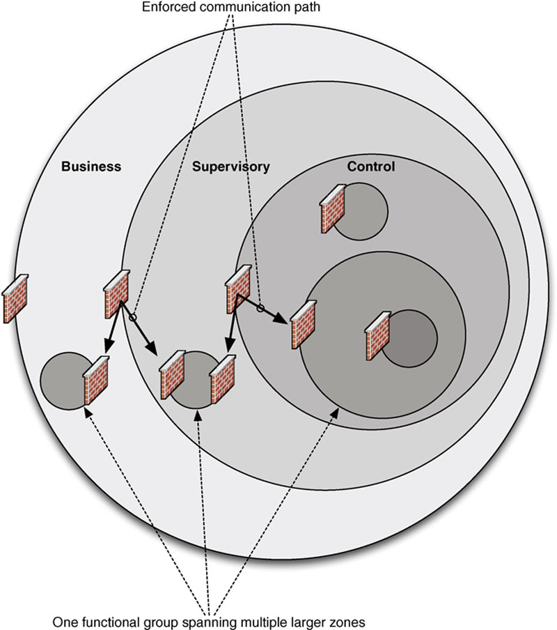
Figure 10.2 Zone perimeters.
In scenarios where a zone needs to be extended across another zone boundary (i.e., there are two overlapping zones), consider the functional goals of that extension. For example, in many cases a business user may require access to information originating from within a secure SCADA zone. However, there is no requirement for the business user to communicate back into the SCADA environment. In situations like these, the use of a “semitrusted” or demilitarized zone (DMZ) is recommended, and the use of strong access controls, such as one-way communications, should be considered to prevent network flows from the less-secure or “untrusted” zone(s) to the more secure “trusted” zone(s). One-way communication can be enforced by provisioning network security controls (e.g. the firewalls shown in Figure 10.2) to disallow inbound traffic. These controls should minimize the use of “any” in ruleset fields and specifically define host IP addresses and communication channels (i.e. TCP and UDP ports). A dedicated network security control, such as a data diode or unidirectional gateway, can also be deployed.
Network segmentation
In accordance with the Principle of Least Route (see Chapter 5, “Industrial Network Design and Architecture”), a device that does not physically belong to a zone should not be allowed to directly connect to that zone or to any device within that zone. This is the primary reason networks consist of one or more semitrusted “DMZs” that act as an intermediate connection between the devices that possess both similar and different functional goals while residing in two different zones (i.e. a business user needing ICS historical data).
In many cases, there will be secondary devices identified that have access to or are connected to a zone, such as a printer or storage device that may provide network connectivity. An example is a network printer that has a Wi-Fi interface, which may be enabled by default. These aberrations are easy to overlook, but must be addressed if the zone is to be secured. This is one reason that thorough security risk and vulnerability assessments need be performed (see Chapter 8, “Risk and Vulnerability Assessments”).
It may not be possible in other cases to clearly identify the boundaries of a zone in terms of network design. For example, if supervisory, control, and enterprise systems are all interconnected via a flat network (a network that is switched purely at Layer 2, without network routing) or a wireless network, it will not be possible to isolate zones through subnetting. In these cases, some other means of logical network segmentation must be used. For example, VLANs could be used to separate devices that are in different zones by segmenting the network at Layer 2 of the Open Systems Interconnection (OSI) model. Another approach could be to implement a technology known as “variable-length subnet masking” (VLSM), which manipulates the Subnet Mask and Default Gateway parameters of a network interface restricting those devices that can actually communicate at the network layer (OSI Layer 3) without introducing any new Layer 3 devices. Alternately, a next-generation firewall could be used on the conduit between zones to segment the devices at Layer 7 of the OSI model. Each has its strengths, and ideally zone separation should be enforced at all seven layers; if budgets and operational overhead were of no consideration, this might even be possible. Realize that the use of VLANs and VLSM only provide moderate levels of cyber security defense as described in Chapter 5, “Industrial Network Design and Architecture,” and is not recommended for networks that require higher levels of security typically accomplished using physical segmentation mechanisms.3
The following method is effective for zone separation:
• Identify and document all network connections into or out of each zone (i.e. identify entry/exit points that form conduits).
• For each conduit
– Start at Layer 1 (the physical layer) and work up to Layer 7 (application layer).
– For each layer, assess if network segmentation at this layer is feasible for that conduit (see Chapter 5, “Industrial Network Design and Architecture” for details on segmenting networks at different layers).
– For more critical conduits, aim for greater segmentation—enforce network segmentation through the use of a mixture of Layer 1 data diode or unidirectional gateway, Layers 3–4 switching and application segmentation, and next-generation firewalls at Layers 5–7.
– For each desired layer of segmentation, implement appropriate network security and access controls to enforce that segmentation.
– Provide sufficient monitoring capabilities with each security control deployed to support event consolidation and reporting mechanisms to assist in potential security breaches.
Zones and security policy development
A distinct milestone is reached once zones and conduits are defined and the necessary adjustments to the network architecture are made. With defined zones and conduits in place, the organization is armed with the information needed to satisfy several compliance requirements of NERC CIP, Chemical Facility Anti-Terrorism Standards (CFATS), and so on, plus other industry-recognized standards like ISO 27000 and ISA 62443.
Documenting all zones within the context of the organization’s security policy provides many benefits, by clearly identifying what systems may be accessed by what other systems, and how. These access requirements will facilitate policy documentation for compliance, security training and review materials, and similar security policy functions required by NERC CIP-003-3,4 ISA 62443-3-3 FR-5,5 CFATS Risk Based Performance Standards Metric 8.2,6 and Nuclear Regulatory Commission (NRC) 10 CFR 73.54 / NRC RG 5.71 section C.3.2.7
Using Zones within security device configurations
Documentation can be a function of security as well as compliance. Firewalls, intrusion detection and intrusion prevention systems (IDS/IPS), Security Information and Event Management (SIEM) systems, and many other security systems support the use of variables, which are used to map hard security configurations to organizational security policies.
For each zone, the following list should be maintained at a minimum:
• Devices belonging to the zone, by IP address and preferably by MAC address as well.
• Software inventory for devices contained within the zone including basic platform applications (operating system, common support tools, etc.) and specialized applications (ICS applications, configuration tools, device drivers, etc.).
• Users with authority over the zone, by username or other identifier, such as Active Directory Organization Unit or Group.
• Protocols, Ports, and Services in use within the zone.
• Technologies that are specifically forbidden from deployment within the zone, such as cloud-based applications that must communicate with disallowed zones, legacy operating systems, insecure wireless technologies, and automated port scanning tools to name a few.
If additional metrics are identifiable, additional lists should be created. Depending on the number of zones that have been defined, this may require several lists—five (device, users, applications, ports/services, technologies) for every established zone. Additional lists could also be maintained; for example, users by shift or users by computer, in addition to users defined solely by zones. However, unless there is a centralized authentication system in use, maintaining these lists may be cumbersome, and could increase the likelihood of a misconfiguration being overlooked.
When finished, these variables will appear as follows:

The creation of these variables will assist in the creation of firewall and IDS rules for the enforcement of the zone’s perimeter, as discussed under “Implementing Network Security and Access Controls,” and will also allow for security monitoring tools to detect policy exceptions and generate alarms, as discussed in Chapter 12, “Security Monitoring of Industrial Control Systems.”
To define a usable variable that maps to a range of IP addresses that may further define a zone, ipvar ControlSystem_Zone01_Devices [192.168.1.0/24, 10.2.2.0/29] is used, and then that variable is referenced within a specific rule using $ControlSystem_Zone01_Devices. This is a logical extension of the classic $HOME_NET variable used in many IDS policies, only applied to a specific zone. This allows for exception-based detection of unauthorized behavior within the zone, as seen in the following rule header to detect any traffic with a destination IP of a device within the defined control system zone:
alert tcp any any -> $ControlSystem_Zone01_Devices any
It is also possible to use “negation” and signify all entities not contained in the variable, as seen in the following rule that will detect any traffic with a destination IP of a device within the defined control system zone and source IP that is “not” in the zone:
alert tcp !$ControlSystem_Zone01_Devices any
-> $ControlSystem_Zone01_Devices any
With zones defined, and relevant variables defined for each, the zones can now be secured using perimeter and host security devices. More details will be provided on variables later in section “Intrusion Detection and Prevention (IDS/IPS) Configuration Guidelines.”
Implementing network security controls
Establishing network security to protect access to a defined zone is actually an enforcement of conduits. The rules used align with the communication channels contained within the conduit. Network security controls protect against unauthorized access to the enclosed systems and also prevent the enclosed systems from accessing external systems from the inside-out. To effectively secure inbound and outbound traffic, two things must occur:
1. All inbound and outbound traffic must be forced through one or more known network connections that are monitored and controlled.
2. One or more security devices must be placed in-line at each of these connections (this could be a security capability built into network communication switches and routers).
For each zone, appropriate security devices should be selected and implemented using the recommendations given next.
Selecting network security devices
At a minimum, some form of network firewall is usually required. Additional security—provided by IDS, IPS, and a variety of specialized and hybrid devices, such as Unified Threat Management (UTM) devices, Network Whitelisting devices, Application Monitors, and Industrial Protocol Filters—may be desired as well, depending upon the specific situation. Typically, the security level or criticality of the zone (see “Criticality”) dictates the degree of security that is required. Table 10.1 maps the criticality of a zone to required security measures of NERC CIP and NRC CFR 73.54, as well as recommended enhancements to improve security beyond regulatory requirements.
Table 10.1
Perimeter Security Requirements by Criticality
| Criticality | Required Security | Recommended Enhancements |
| 4 (highest) | NRC CFR 73.54: Unidirectional Perimeter, NERC CIP 005: Firewall or IDS or IPS | Application layer monitoring, Firewall, IDS and IPS |
| 3 | NRC CFR 73.54: Unidirectional Perimeter, NERC CIP 005: Firewall or IDS or IPS | Application layer monitoring, Firewall, IDS and IPS |
| 2 | NERC CIP 005: Firewall or IDS or IPS | Firewall and IDS and IPS |
| 1 | NERC CIP 005: Firewall or IDS or IPS | Firewall and IPS |
| 0 (lowest) | NERC CIP 005: Firewall or IDS or IPS | Firewall and IPS |
Table 10.1 recommends that both a firewall and an IPS be used at each security perimeter. This is because firewalls and IPS devices serve different functions. Firewalls enforce what types of traffic are allowed to pass through the perimeter by what is called “shallow packet inspection.” Intrusion Prevention Systems on the other hand perform “deep-packet inspection” (DPI) by closely examining the traffic that is allowed through in order to detect “legitimate” traffic with malicious intent—that is, exploit code, malware, and so on—that is transferred over allowed paths. Using both devices together provides two mutual benefits: first, it allows the IPS to perform inspection of the “content” of all traffic allowed in through the firewall; second, the firewall limits the allowed traffic based on the defined parameters of the security zone, freeing the IPS to focus its resources on just that traffic and therefore enabling it to enforce a more comprehensive and robust set of IPS rules.
It is important to understand the distinction between “detection” and “prevention” in the context of intrusion prevention systems. Recall that the most important priorities of industrial networks are availability and performance. In other words, the network cannot tolerate accidental dropping of packets between hosts that are located on levels low within the ISA 95 model (i.e. Levels 1–3). This would occur if the security device generates a “false positive” and mistakenly interprets a valid packet as invalid and blocks it from reaching its destination. However, this may not necessarily be the case between industrial and business zones (i.e. Levels 3 and 4). This is the reason IDS is the preferred security appliance within industrial zones (placed “out-of-band” to network traffic) and IPS is used between industrial and business zones, or between semitrusted DMZs and untrusted business zones (placed “in-line” to all network traffic).
We have also learned that industrial protocols consist of common standards like Modbus and DNP3, but also depend heavily on vendor-specific proprietary protocols that have been optimized for a particular system. It is not common for major IT network security suppliers like Cisco, HP ProCurve, Juniper, Checkpoint, and others to offer solutions for industrial networks. So what options exist to implement advanced DPI analysis with industrial protocols? The answer is a new class of industrial security appliances that are industrial protocol aware and possess the capability to analyze and inspect both open and proprietary protocols. Companies supplying these devices include Tofino/Belden, Secure Crossing, ScadaFence, SilentDefense, and others. At the time this book was written, many other startups were in progress, and readers are encouraged to research the market thoroughly in order to fully understand all of the available options. In addition, OEM-branded solutions or recommended third-party solutions may be available from your control system vendors. Once an appropriate solution is selected and deployed, DPI can then be used to analyze specific industrial protocol functions. Figure 10.3 illustrates the increased security capability of firewalls, IDS/IPS devices, and application session monitoring systems.
Figure 10.3 Relative capabilities of security devices to detect threats using DPI.
In the most critical areas, application-layer session monitoring provides a valuable and necessary level of assurance, as it is able to detect low-level protocol anomalies (such as a base64-encoded application stream inside of an HTTP layer 4 80/tcp session, used by many APTs and botnets) and application policy violations (such as an unauthorized attempt to write a new configuration to a PLC). However, unless monitoring very simple application protocols where the desired contents are distinctly packaged within a single packet or frame, the application session must be reassembled prior to monitoring as illustrated in Figure 10.4.
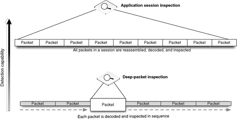
Figure 10.4 Application session inspection vs. deep packet inspection.
The most stringent network security device may be the data diode, also referred to as a unidirectional gateway. A data diode is, very simply, a one-way network connection—often a physically restricted connection that uses only one fiber-optic strand from a transmit/receive pair. By only using TX optics on the source side, it is physically impossible for any digital communications to occur in a highly sensitive network area containing control system devices, while supervisory data may be allowed to communicate out of that highly secure zone into the SCADA DMZ or beyond. In certain instances, such as for the storage of highly sensitive documents, the diode may be reversed, such that information can be sent into a secure zone that is then physically prevented from communicating that information back outside of the zone. During this “flip” phase, the previous communication flow should be terminated to disable any ability for two-way communication to occur at any point in time through the gateway.
Implementing network security devices
Once appropriate security product(s) have been selected, they must be installed and configured correctly. Luckily, the process of identifying, establishing, and documenting zones will simplify this process. The following guidelines will help to configure firewalls, IDS/IPS devices, and application monitors using the variables defined earlier under “Establishing Zones.”
Firewall Configuration Guidelines
Firewalls control communication using a defined configuration policy called a “rule set,” typically consisting of Allow (accept) and Deny (drop) statements. Most firewalls enforce a configuration in sequence (either by “lower-to-higher” number or simply from “top-to-bottom”), such that they start with a broadly defined policy, such as Deny All, which will drop all inbound traffic by default. Once a packet has satisfied a given rule, no further processing occurs, making rule order very critical. These broad rules are tailored by adding before them subsequent, more focused rules. Therefore, the following firewall policy would only allow a single IP address to communicate outside of the firewall on port 80/tcp (HTTP).
Allow 10.0.0.2 to Any Port 80
Deny All
Had this rule order been reversed, starting with the “Deny All” policy, no traffic would be allowed through the firewall, since all traffic would have been dropped by the first rule.
Determining what rules should be configured is typically easier in an industrial network because the nature of an industrial network is such that there is no need to accommodate the full diversity of applications and services typically found in an enterprise network. This is especially true when configuring a specific firewall against a specific zone-to-zone conduit—the zone will by its nature be limited in scope, resulting in concise firewall policies. In general, the more firewalls deployed on conduits, the simpler the configuration will be on each firewall. This is in contrast to attempting to utilize a single firewall (or firewall pair) and managing all rule sets on a single appliance.
The method of properly configuring a zone firewall is as follows:
1. Begin with bidirectional Deny All rules placed at the end of the configuration
2. Configure specific exceptions, using the defined variables $ControlSystem_Zone01_Devices and $ControlSystem_Zone01_PortsServices.
3. Verify that all Allow rules are explicitly defined—in other words, prevent the use of “Any” parameters for IP Address and destination Port/Service entries.
One simple way to configure a firewall is to follow the guidelines of the National Infrastructure Security Coordination Center (NISCC) “Good Practice Guide on Firewall Deployment for SCADA and Process Control Networks,” using the defined zone variables as detailed in Table 10.2.12
Table 10.2
NISCC Firewall Configuration Guidelines with Zone Variablesa
| NISCC Recommendations | Example Rule Using Zone Variables | Notes |
| Start with universal exclusion as a default policy | Deny All / Permit None | Firewalls should explicitly deny all traffic inbound and outbound as the default policy. |
| Ports and services between the control system environment and an external network should be enabled and permissions granted on a specific case by case basis | Allow 10.2.2.120 port 162 to 192.168.1.15 port 162#Allow SNMP traps from router ip 10.2.2.120 to network management station ip 192.168.1.15, authorized by John Doe on April 1 2005 | Comments used within the firewall configuration file can be used to document special cases, permissions, and other details. |
| All “permit” rules should be both IP address and TCP/UDP port specific, and stateful if appropriate, and shall restrict traffic to specific IP address or range of addresses | N/A | This guideline can be enforced by using $ControlSystem_Zone01_Devices and $ControlSystem_Zone01_PortsServices to define rules. |
| All traffic on the SCADA and DCS network(s) are typically based only on routable IP protocols, either TCP/IP or UDP/IP; thus, any non-IP protocol should be dropped | N/A | By using $ControlSystem_Zone01_PortsServices within all defined rules, only protocols explicitly allowed within that zone will be accepted by the firewall, and all others will be dropped by the overarching Deny All rule. |
| Prevent traffic from transiting directly from the Process Control / SCADA network to the enterprise network; all traffic should terminate in the DMZ | Deny [Not $Neighboring Zone1, Not $Neighboring Zone2] to $ControlSystem_Zone01_DevicesDeny $ControlSystem_Zone01_Devices to [Not $Neighboring Zone1, Not $Neighboring Zone2] | By configuring a rule on each zone that explicitly denies all traffic to and from any zone that is NOT a neighboring zone will prevent any transitive traffic. All traffic will need to be terminated and reestablished using a device local to that zone. |
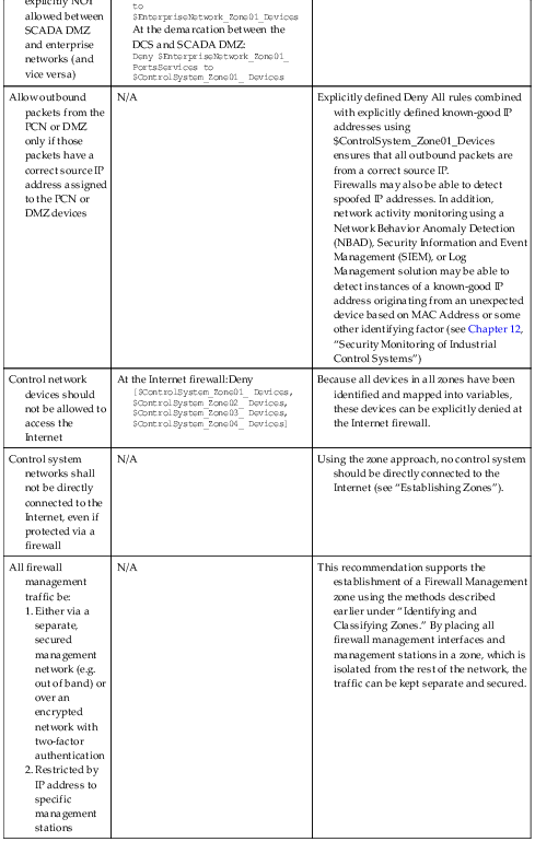
| Any protocol allowed between the DCS and the SCADA DMZ is explicitly NOT allowed between SCADA DMZ and enterprise networks (and vice versa) | At the demarcation between the enterprise network and SCADA DMZ: Deny $ControlSystem_Zone01_PortsServices to $EnterpriseNetwork_Zone01_Devices At the demarcation between the DCS and SCADA DMZ: Deny $EnterpriseNetwork_Zone01_ PortsServices to $ControlSystem_Zone01_ Devices | These rules enforce the concept of “disjointing” protocols, and further prevents transitive communication from occurring across a zone. |
| Allow outbound packets from the PCN or DMZ only if those packets have a correct source IP address assigned to the PCN or DMZ devices | N/A | Explicitly defined Deny All rules combined with explicitly defined known-good IP addresses using $ControlSystem_Zone01_Devices ensures that all outbound packets are from a correct source IP. Firewalls may also be able to detect spoofed IP addresses. In addition, network activity monitoring using a Network Behavior Anomaly Detection (NBAD), Security Information and Event Management (SIEM), or Log Management solution may be able to detect instances of a known-good IP address originating from an unexpected device based on MAC Address or some other identifying factor (see Chapter 12, “Security Monitoring of Industrial Control Systems”) |
| Control network devices should not be allowed to access the Internet | At the Internet firewall:Deny [$ControlSystem_Zone01_ Devices, $ControlSystem_Zone02_ Devices, $ControlSystem_Zone03_ Devices, $ControlSystem_Zone04_ Devices] | Because all devices in all zones have been identified and mapped into variables, these devices can be explicitly denied at the Internet firewall. |
| Control system networks shall not be directly connected to the Internet, even if protected via a firewall | N/A | Using the zone approach, no control system should be directly connected to the Internet (see “Establishing Zones”). |
| All firewall management traffic be:
1. Either via a separate, secured management network (e.g. out of band) or over an encrypted network with two-factor authentication
2. Restricted by IP address to specific management stations
| N/A | This recommendation supports the establishment of a Firewall Management zone using the methods described earlier under “Identifying and Classifying Zones.” By placing all firewall management interfaces and management stations in a zone, which is isolated from the rest of the network, the traffic can be kept separate and secured. |

a National Infrastructure Security Coordination Center, NISCC Good Practice Guide on Firewall Deployment for SCADA and Process Control Networks. British Columbia Institute of Technology (BCIT). February 15, 2005.
Intrusion Detection and Prevention (IDS/IPS) Configuration Guidelines
IDS and IPS devices inspect network traffic for signs of malicious code or exploits. Intrusion Detection refers to passive inspection and is typically placed “out-of-band” of network flow. IDS and IPS examine traffic and compare it against a set of detection signatures, and taking some predefined action when there is a match. The main difference between the two lies in the actions allowed when there is a match. IDS actions can include Alert (generate a custom message and log the packet), Log (log the packet), and Pass (ignore the packet), while IPS actions can also include Drop (drop the packet and log it), Reject (drop the packet and initiate a TCP reset to kill the session), and Drop (drop the packet, but do not log it). In addition, both IDS and IPS rules can use the Activate and Dynamic actions, the former of which activates another rule, and the latter of which remains idle until activated by an Activate rule.13
An enabled collection of IDS/IPS detection signatures is referred to as an IDS/IPS policy, and this policy will dictate what types of threats may be detected by the device, as well as the degree and scope of events that will be generated. This collection should align with the list of threats and vulnerabilities that were previously defined for the security zone, as described in “Establishing Security Zones and Conduits” in Chapter 9. While active blocking of malicious traffic is important, the IDS/IPS events that are generated can also be analyzed to provide other important indicators—including attribution, network behavior, payloads, and larger threat incidents (see Chapter 12, “Security Monitoring of Industrial Control Systems”). Signatures generally follow a format similar to a firewall rule, where there is an identified source and destination address and/or port—with the primary difference being the “action” that is performed in the case of a match. In addition, IDS/IPS signatures may match against specific contents of a packet, looking for patterns within the packet that indicate a known exploit (i.e. a “signature”). Common IDS/IPS signature syntax follows the de facto standards defined by Snort, an open-source IDS project owned by Sourcefire. An example signature is written as follows:
[Action] [Protocol] [Source Address] [Source Port] [Direction Indicator] [Destination Address] [Destination Port] [Rule Options]
which when written in correct syntax looks like
drop tcp 10.2.2.1 any -> 192.168.1.1 80 (flags: <optional tcp header flags>; msg: “<message text>”; content: <this is what the rule is looking for>; reference: <reference to external threat source>;)
To highlight the difference between a firewall rule and an IDS/IPS signature, consider the following example:
drop tcp 10.2.2.1 any -> 192.168.1.1 80
Without any rule options, the previous rule is essentially the same as the firewall rule Deny src-ip 10.2.2.1 dst-port any, which would block all traffic originating from 10.2.2.1 destined for IP address 192.168.1.1 on 80/tcp, effectively prevent that user from accessing web services on the destination (via HTTP on 80/tcp). However, the ability to match packet contents within the rule options enables an IDS/IPS device to control traffic at a much more granular level, such as
drop tcp 10.2.2.1 any -> 192.168.1.1 80 (msg: “drop http POST request”; content: “POST”;)
This rule functions differently, only dropping traffic from the source address in question if the HTTP traffic contains a POST request (used by many web forms or applications attempting to upload a file to a web server over HTTP).
As with a firewall configuration, determining the exact IDS/IPS policy to be enforced is the first step in correctly configuring the device. The zone variables defined earlier under “Establishing Zones” are valuable tools that can be used to write succinct and highly relevant signatures. However, unlike a firewall that ends with a simple Deny All rule, an IDS/IPS typically employs a default “Allow All” rule, and therefore should be deployed “large”—with many active signatures—and then pruned back to the specific requirements of the zone. A method of properly configuring an IDS/IPS is as follows:
1. Begin with a more robust signature set, with many active rules.
2. If a protocol or service is not allowed in the zone, remove any specific detection signature associated with that protocol or service, and place with a broader rule that will block all traffic from that protocol or service (i.e. drop unauthorized ports and services) in the L3–L4 device (router or firewall) that exists upstream of the IDS/IPS.
3. If a protocol or service is allowed in the zone, keep all detection signatures associated with that protocol or service active.
4. For all active signatures, assess the appropriate action, using Table 10.3.
5. Keep all IDS signatures current and up to date.
Table 10.3
Determining Appropriate IDS/IPS Actions
| Allowed Port or Service? | Source | Destination | Criticality of Service | Severity of Event | Recommended Action | Note |
| No | Any | Any | Any | Any | Drop | Any communication not explicitly allowed within the zone should be blocked to disrupt unauthorized sessions and deter an attack. |
| Yes | Trusted Zone | Trusted Zone | High | Any | Alert | Active blocking of traffic that originates and terminates within a zone could impact operations. For example, a false positive could result in legitimate control system traffic being blocked. |
| Yes | Trusted Zone | Trusted Zone | Low | Any | Alert or Pass | For noncritical services, logging is recommended but not necessary (Alert actions will provide valuable event and packet information that could assist in later incident investigations). |
| Yes | Untrusted Zone | Trusted Zone | High | Low (events from obfuscated detection signatures or informational events) | Alert | Many detection signatures are broad to detect a wider range of potential threat activity. These signatures should Alert only to prevent unintentional interruption of control system operations. |
| Yes | Untrusted Zone | Trusted Zone | High | High (explicit malware or exploit detected by a precisely tuned signature) | Drop, Alert | If inbound traffic to a critical system or asset contains known malicious payload, the traffic should be blocked to prevent outside cyber incidents or sabotage. |
| Yes | Trusted Zone | Semitrusted Zone (explicitly allowed destination address) | Any | Any | Alert | This traffic is most likely legitimate. However, alerting and logging the event will provide valuable event and packet information that could assist in later incident investigations. |
| Yes | Trusted Zone | Untrusted Zone (unknown destination address) | Any | Any | Drop | This traffic is most likely illegitimate. Generated alerts should be addressed quickly: if the event is a false positive, necessary traffic could be unintentionally blocked; if the event is a threat, it could indicate that the zone has been breached. |


Remember that an IDS or IPS can be used in a purely passive mode, to analyze traffic that is allowed, including traffic within a zone (that is, in the conduits between two devices within the same zone, that do not cross a zone perimeter). Passive monitoring will generate alerts and logs that can be useful in many security operations, including forensic investigations, threat detection, and compliance reporting (see Chapter 12, “Security Monitoring of Industrial Control Systems,” and Chapter 13, “Standards and Regulations”).
IDS/IPS rules should be tailored to the appropriate zone using the variables defined in Chapter 9 “Establishing Zones and Conduits.” A typical Snort variable is established using the var command, as follows:
var VARIABLE_NAME <alphanumeric value>.
A specialized ipvar and portvar variable are used exclusively for IP addresses and ports, respectively.16 In the zone method described earlier under “Establishing Zones,” variables would be defined as
ipvar ControlSystem_Zone01_Devices [192.168.1.0/24, 10.2.2.0/29]
var ControlSystem_Zone01_Users [jcarson, jrhewing, kdfrog, mlisa]
portvar ControlSystem_Zone01_PortsServices [502, 135, 12000:12100]
These variables can then be used extensively throughout the active detection signatures. For example, a signature designed to detect a known SCADA buffer overflow attack that is available within the Metasploit framework might appear as follows (the following rule has been deliberately obfuscated; the complete rule can be obtained from Digital Bond at www.digitalbond.com):
alert tcp !$ControlSystem_Zone01_Devices any -> $ControlSystem_Zone01_Devices 20222 (msg: “SCADA ODBC Overflow Attempt”; content: <REMOVED - long string in the second application packet in a TCP session>; reference:cve,2008-2639; reference:url,http://www.digitalbond.com/index.php/research/ids-signatures/m1111601/; sid:1111601; rev:2; priority:1;)
Additional examples include signatures designed to specifically block known infection vectors used by Stuxnet.17 The first example looks for one of the early delivery mechanisms for the Stuxnet malware that utilized a shortcut image file delivered via a WebDav connection. The second example detects Siemens WinCC connection attempts by logging into the WinCC database via a specific username and password combination, used in early Stuxnet propagation phases:
tcp !$ControlSystem_Zone01_Devices $HTTP_PORTS -> $ControlSystem_Zone01_Devices any (msg: “Possible Stuxnet Delivery: Microsoft WebDav PIF File Move Detected”; flow:from_server; content: “MOVE”; offset:0; within:5; content: .“pif”; distance:0; classtype:attempted-user; reference:cve, 2010-2568; reference:osvdb,66387; reference:bugtraq,41732; reference:secunia,40647; reference:research,20100720-01; sid:710072205; rev:1;)
tcp any any -> any 1433 (msg: “Possible Stuxnet Infection: Siemens Possible Rootkit.TmpHider connection attempt”; flow:to_server; content: “Server=|2e 5c|WinCC|3b|uid=WinCCConnect|3b|pwd=2WSXcder”; classtype:suspicious-login; reference:cve,2010-2772; reference:osvdb,66441; reference:bugtraq,41753; sid:710072201; rev:2;)
Recommended IDS/IPS Rules
Basic recommendations for IDS/IPS configuration include active rules to
1. Prevent any undefined traffic from crossing zone boundaries (where the disruption of the communication will not impact the reliability of a legitimate service).
2. Prevent any defined traffic containing malware or exploitation code from crossing zone boundaries.
3. Detect and log suspicious or abnormal activity within a zone (see “Implementing Host Security and Access Controls” and Chapter 11, “Security Monitoring of Industrial Control Systems”).
4. Log normal or legitimate activity within a zone, which may be useful for compliance reporting (see Chapter 13, “Standards and Regulations”).
5. Log all traffic originating from remote access clients, which may be useful for compliance reporting and acceptable use confirmation.
The greater the extent of functional isolation and separation into defined zones, the more concise and effective the IDS/IPS policy will be. Some basic IDS/IPS rules suitable for use in zone perimeters include the following:
• Block any industrial network protocol packets that are the wrong size or length.
• Block any network traffic that is detected inbound to or outbound from any zone where that is not expected or allowed.
• Block any industrial network protocol packets that are detected in any zone where that protocol is not expected or allowed.
• Alert any authentication attempts, in order to log both successful and failed logins.
• Alert any industrial network port scans.
• Alert any industrial network protocol function codes of interest, such as:
• “Write” functions, including codes that write files or that clear, erase, or reset diagnostic counters.
• “System” functions, including codes that stop or restart a device.
• “System” functions that disable alerting or alarming.
• “Read” functions that request sensitive information.
• “Alarm” or “Exception” codes and messages.
Consideration should be given when defining IDS/IPS rules as to whether you want to begin analysis before or after the TCP three-way handshake has taken place—of course this is limited to only those applications and services that depend on TCP as their transport protocol. It is not possible to perform content or deep-packet inspection of data that has not completed the three-way handshake. However, this type of information can be very valuable in determining if a rogue or malicious host is “probing” for potential targets and attempted to enumerate and fingerprint the network under consideration. The example rule given next can be used to identify any traffic that is attempting to communicate with an ICS host via the EtherNet/IP protocol at the onset of the three-way handshake—an initial segment is sent with only the SYN flag set in the TCP header:
alert tcp !$ControlSystem_Zone01_Devices any -> $ControlSystem_Zone01_Devices 44818 (msg: “Attempt to connect to ICS device from another zone using known service”; flags: S; <additional options>)
While almost any IDS/IPS device may be able to detect and trigger upon industrial network protocols by searching for specific values in a packet, those devices that can perform stateful inspection of application contents including inspection of function codes, commands, and additional payloads will provide more value, and will generally be capable of detecting threats with greater efficacy. Many industrial protocols are not easily parsed by traditional IDS/IPS engines, and often utilize message fragmentation making them very difficult to analyze with consistent results. Therefore, it is recommended that “industrial” products with application inspection capability be used. This class of product will be more capable of analyzing the application layer protocols and how they are used, and will be useful for detecting injection attacks, malformed messages, out of sequence behavior and other potentially harmful activity.
Anomaly-Based Intrusion Detection
Only signature-based detection has been discussed at this point. Anomaly detection is also supported on many IDS/IPS systems using statistical models to detect when something unusual is happening. This is based on the premise that unexpected behavior could be the result of an attack.
The exact capabilities will vary from product to product, as there is no standard anomaly detection mechanism. Theoretically, anything monitored by the IDS could be used for anomaly detection. Because network flows are highly quantifiable, anomaly detection is often used to identify abnormal behavior in what devices are communicating between each other, and how. Referred to as Network Anomaly Detection, these systems are able to detect a sudden increase in outbound traffic, an increase in sessions, an increase in total bytes transmitted, an increase in the number of unique destination IP addresses, or other quantifiable metrics.
Anomaly detection is useful because it does not require an explicitly defined signature in order to detect a threat. This allows anomaly detection systems to identify zero-day attacks or other threats for which no detection signature exists. At the same time, however, anomaly detection tends toward a higher number of false positives, as a benign change in behavior can lead to an alert. Anomaly-based threat detection is typically used passively for this reason by generating alerts rather than actively blocking suspect traffic.
In industrial networks—especially in well-isolated control system zones—network behavior tends to be highly predictable, making anomaly detection more reliable.
Anomaly detection systems may be referred to as “rule-less” detection systems. This is because they do not pattern match against a defined signature, although they do use rules. Unlike a normal IDS rule, anomaly rules are often based on thresholds and/or statistical deviations, such as in the following example:
TotalByteCount from $Control_System_Zone01_Devices increases by >20%
An example of a threshold rule would use a hard upper- or lower-limit, most likely derived automatically by the anomaly detection system:
TotalDestinationIPs>34
As a general guideline, the greater the variation of network traffic being monitored, the greater the chances of anomaly detection rules generating a false positive result.
Anomaly detection can be used across devices as well, coupled with an information consolidation tool, such as a SIEM system. This system-level anomaly detection is discussed in more detail in Chapter 11, “Exception, Anomaly, and Threat.”
Protocol Anomaly Detection
Another type of anomaly detection looks specifically at the protocol: malformed messages, sequencing errors, and similar variations from a protocol’s “known good” behavior. Protocol anomaly detection can be very powerful against unknown or zero-day exploits, which might attempt to manipulate protocol behavior for malicious purposes. However, be very careful when deploying protocol anomaly detection, as many legitimate products from legitimate ICS vendors utilize protocols that have been implemented “out of spec”—either using proprietary protocol extensions or altering the protocol’s implementation in a product to overcome some limitation in the “pure” standard. Knowing this, protocol anomaly detection of industrial protocols can be subject to high rates of false positives, unless some effort has been made to “tune” the detection parameters to the nuances of a particular vendor or product.
Application and Protocol Monitoring in Industrial Networks
Because many industrial operations are controlled using specialized industrial network protocols that issue commands, read and write data, perform device configuration, and so on using defined function codes, specialized devices can leverage that understanding along with firewall, IDS, and IPS technology to enforce communications based on the specific operations being performed across the network.
In addition to the inspection of industrial protocol contents (e.g. DNP3 function codes), the applications themselves—the software that controls how those protocols are used—can also be inspected. This degree of Application Monitoring, also referred to as Session Inspection, allows the contents of an application (e.g. human–machine interface (HMI), Web Browser) to be inspected even though it might exist across a large number of individual packets. That is, inspection can occur up to and include the contents of a file being transferred to a PLC, a virus definition downloaded from the web browser of an update server, and so on. Application Monitors provide a very broad and very deep look into how network traffic is being used, and are therefore especially useful in environments where both control systems and enterprise protocols and applications are in use.
Many specialized security devices are available for ICS and other control system environments that use either application or protocol monitoring to this degree. At the time of this writing, these devices include the Tofino Security Appliance and the Secure Crossing Zenwall Access Control Module, as well as other broader-use enterprise Application Data Monitors. The two former devices were designed specifically to identify the operations being performed within industrial protocols and to prevent unauthorized operations. The latter refers to a more general-purpose enterprise security appliance, which is able to support the most common industrial network protocols. Each of these specialized devices has specific strengths and weaknesses, which are summarized in Table 10.4.
Table 10.4
A Comparison of Industrial Security Devices
| Security Product | Functionality | Strengths | Weaknesses | Rule Example |
| ICS Firewall | Traffic policy enforcement | Enables isolation of traffic based on networks, ports and services | Does not block hidden threats or exploits within “allowed” traffic | Allow only TCP port 502 (Modbus TCP) |
| ICS IDS/IPS | Detects malware and exploits within traffic | Prevents exploitation of vulnerabilities via authorized ports and services | “Blacklist” methodology can only detect and block known threats | Block Modbus packets containing known malware code |
| ICS UTM or hybrid security appliance | Combines firewall, IDS/IPS, VPN, anti-virus and other security functions | Combination of security functions facilitates “defense in depth” via a single product | Security functions maintain their component weaknesses (i.e. the whole is equal to but not greater than the sum of its parts) Must be updated in order to remain effective | Allow only TCP port 502 with “read only” function codes |
| Allow outbound TCP 502 only via encrypted VPN to other SCADA zones | ||||
| ICS Content Firewall or Application Firewall | Traffic policy enforcement | Enables content-based traffic isolation, based on industrial network protocols | Assesses content of a single packet only (lacks session reassembly or document decode) Difficult to deploy on protocols that utilize packet fragmentation | Allow only “Read only” Modbus TCP functions |
| Deep Session Inspection (application content monitoring) | Session Reassembly | Functions of an ICS content firewall, plus visibility into full application session and document contents to detect APT threats and insider data theft; provides strong security in hybrid enterprise/industrial areas such as ICS DMZ or other semi-trusted zones such as Remote Access | Typically limited to TCP/IP inspection, making session inspection less suitable for deployment in pure control system environments | Alert on Modbus TCP traffic on ports other than TCP 502 |
| File/Content Decode | Alert on any traffic with base64-encoded content | |||
| File/Content Capture | ||||
| Network Whitelist | Allows only defined “good” traffic | Prevents all malicious traffic by allowing only known, good traffic to pass as defined by a fingerprint of acceptable host and protocol relationships. | Requires proper baselining of correct network behavior | Can make legitimate changes in network operations more difficult |


Because these devices are highly specialized, configurations can vary widely. In general terms, a firewall capable of industrial protocol inspection may utilize a rule as follows to block any protocol function from writing a configuration or register, or executing a system command (such as a device restart):
Deny [$ControlSystem_ProtocolFunctionCodes_Write, $ControlSystem_ProtocolFunctionCodes_System]
An IDS capable of industrial protocol inspection may utilize a rule as follows, which looks for a specific function code within a DNP3 packet (DNP3 is supported with both TCP and UDP transports):
tcp any any -> $ControlSystem_Zone01_Devices 20000 (msg: “DNP function code 15, unsolicited alarms disabled - TCP”; content:“|15|”; offset:12; rev:1;)
udp any any -> $ControlSystem_Zone01_Devices 20000 (msg: “DNP function code 15, unsolicited alarms disabled - UDP”; content:“|15|”; offset:12; rev:1;)
In contrast, an application monitor performing full session decode may use syntax similar to the following rule to detect windows .LNK files within application traffic, which could indicate a possible Stuxnet delivery attempt.
FILTER_ID=189
NORM_ID=830472192
ALERT_ACTION=log-with-metadata
ALERT_LEVEL=13
ALERT_SEVERITY=10
DESCRIPTION=A Microsoft Windows .LNK file was detected
EXPRESSION=(objtype==application/vnd.ms-lnk)
Data Diodes and Unidirectional Gateways
Data diodes and unidirectional gateways work by preventing return communications at the physical layer typically over a single fiber-optic connection (i.e. fiber strand). The “transmit” portion generally does not contain “receive” circuitry, and likewise the “receive” does not possess “transmit” capability. This provides absolute physical layer security at the cost of bidirectional communications. Because the connection in reverse direction does not exist, data diodes are true air gaps, albeit in only one direction.
Because many network applications and protocols require bidirectional communication (such as TCP/IP, which requires a variety of handshakes and acknowledgments to establish, maintain, and complete a session), considerations should be taken when using data diodes in order to ensure that the remaining one-way data path is capable of transferring the required traffic. To accommodate this concern, many data diode vendors implement a software-based solution, where the physical diode exists between two “agents.” These agents support a variety of bidirectional applications and their associated communication services, so that the bidirectional requirements can be met fully at each end. The receiving end effectively “spoofs” the behavior of the original transmitter—essentially tricking the application to operate over a one-way link. This allows an additional level of control over the applications and services that can be transmitted over the diode or gateway. An example of enabling DNP3 services over a unidirectional gateway is shown in Figure 10.5. While data diodes are physical layer devices that do not require any specific configuration, the communication servers may need to be correctly configured before these applications work correctly over the diode. Table 10.5 shows the applications and protocols supported using a unidirectional gateway supplied by Waterfall Security.
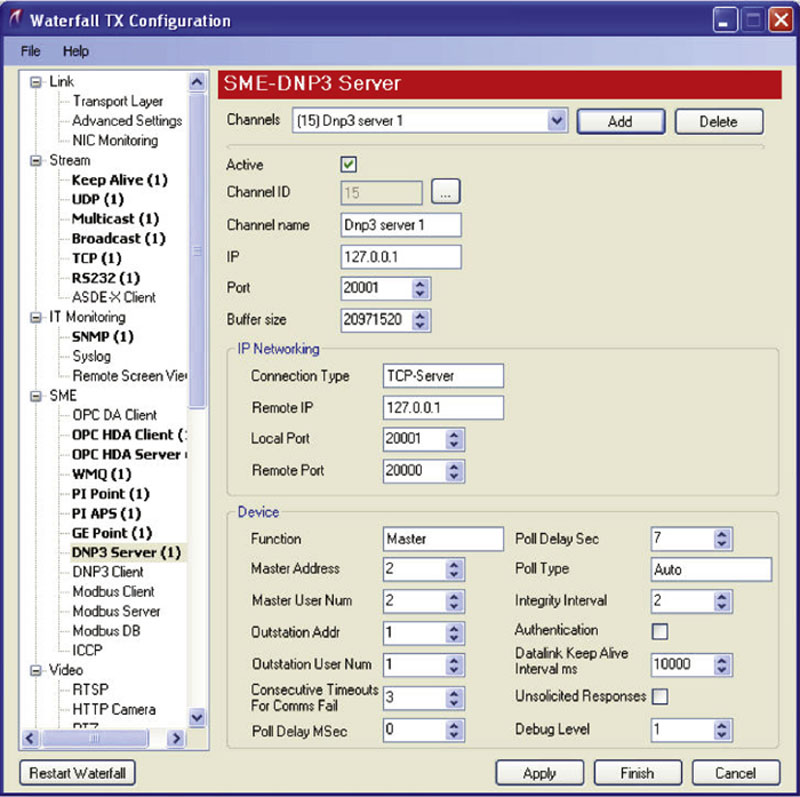
Figure 10.5 Enabling DNP3 over a unidirectional gateway.
Table 10.5
Unidirectional Gateway Application/Protocol Support24
| Application Family | Description |
| Historian | OSIsoft PI GE iHistorian GE OSM Wonderware Historian Instep eDNA |
| Human–Machine Interface | GE iFix Siemens SINAUT Siemens WinCC |
| Control Center Communications | ICCP IEC 60870-104 |
| Remote Access | Remote Screen View |
| File Transfer | FTP FTPS SFTP TFTP RCP CIFS |
| Monitoring | CA SIM CA Unicenter HP OpenView SNMP Log Transfer Syslog |
| Video | ISE |
| Anti-virus | OPSWAT Metascan Norton Updater |
| Middleware | IBM Websphere MQ MS Message Queuing |
| ICS Protocols | OPC-UA OPC-DA (Classic) ICCP Modbus DNP3 Bently-Nevada System 1 |
| Database Replication | SQL Oracle |
| General | UDP TCP Remote Printing Microsoft Backup Tibco EMS |
Implementing host security and access controls
All zones are essentially logical groups of assets. They therefore contain a variety of devices, which may themselves be susceptible to a cyber-attack.
Zones consist of specific devices and applications, and conduits consist of a variety of network communication channels between those devices and applications. This means that all zones will contain at least one device with a network interface, and therefore it is important to secure the device (including OS and applications) and access to that device (including user authentication, network access controls, and vendor maintenance). Host security controls address the questions of who is allowed to use a device, how a device communicates on the network, what files are accessible by that device, what applications may be executed by it, and so on (the monitoring of host activities, such as the communications between hosts within a zone, is also useful for detecting threats). This was discussed in Chapter 9, “Establishing Zones and Conduits,” and will be further discussed in Chapter 12, “Security Monitoring of Industrial Control Systems,” so it will not be discussed further in this chapter.
This section discusses three distinct areas of host security, including
1. Access Control, including user authentication and service availability.
2. Host-Based Network Security, including host firewalls and host intrusion detection systems (HIDS).
3. Anti-malware systems, such as anti-virus (AV) and application whitelists (AWL).
Selecting host cyber security systems
As a matter of best practices, all host access controls and host network security solutions should be implemented on all networked devices. The problem is that not all network devices are capable of running additional security software, and in some cases the software may incur latency or unacceptable processor overhead. Table 10.6 shows which devices are typically capable of running the common methods of host security.
Table 10.6
| HMI or similar device running a modern operating system. Application is not time sensitive. |
• Host Firewall
• HIDS
• Anti-Virus or Application Whitelisting
• Disable all unused ports and services
|
| HMI or similar device running a modern operating system. Application is time sensitive. |
• Host Firewall
• Disable all unused ports and services
• Optional: Application Whitelisting (will require testing to ensure imposed latency is acceptable)
|
| PLC, RTU, or similar device running an embedded commercial OS. |
• Host Firewall or HIDS if available
• External security controls
|
| PLC, RTU, IED or similar device running an embedded operating environment. |
• External security controls
|

Where possible, one option of each type—access control, network security, and anti-malware—should be used on each device. Especially where host security options are not possible, an external security control should be implemented.
Host Firewalls
A host firewall works just like a network firewall, and acts as an initial filter between the host and any attached network(s). The host firewall will allow or deny both inbound and outbound traffic based on the firewall’s specific configuration. Host firewalls are typically session-aware firewalls that allow control over distinct inbound and outbound application sessions. Unlike network-based firewalls that can monitor all traffic entering a network zone via a defined conduit, host-based firewalls can only inspect traffic that is either sent directly to the device or traffic that uses a broadcast address.
As with network firewalls, host firewalls should be configured according to the guidelines presented under “Firewall Configuration Guidelines”—starting with Deny All policies, and only adding Allow rules for the specific ports and services used on that particular asset.
Many organizations believe that hosts should be protected from network-based attacks. In doing so, their attention is paid to only configuring the host-based firewall inbound or “ingress” rules. Recent studies around security controls to protect against advanced targeted attacks (those that are typically the most difficult to prevent) have shown that overall network resilience to cyber events can be improved by also deploying outbound or “egress” rules on these firewalls.20 This effectively contains or isolates that malware to the compromised host, and offers significant defenses against information leakage, C2 communication, and lateral movement and infection. Implementing a simple outbound rule limiting communication to IP addresses within the allowed zones and conduits could have prevented the consequences (C2 communication, payload download, OPC enumeration, etc.) resulting in the installation of trojanized ICS software during the Dragonfly/Havex campaign in 2013–2014.
Host IDS
Host IDS (HIDS) work like Network IDS, except that they reside on a specific asset and only monitor systems internal to that asset. HIDS devices typically monitor system settings and configuration files, applications, and/or sensitive files.21 These devices are differentiated from anti-virus and other host security options in that they can perform network packet inspection, and can therefore be used to directly mimic the behavior of a Network IDS by monitoring the host systems network interface(s) to detect or prevent inbound threats. HIDS can be configured using the information presented under “Intrusion Detection and Prevention (IDS/IPS) Configuration Guidelines.” Because a HIDS may also be able to inspect local files, the term is sometimes used for other host-based security devices, such as anti-virus systems, or propriety host security implementations that provide overlapping security functions.
A HIDS device will generate alerts detailing any violations of the established policy similar to a Network IDS. If the system is able to actively block the violation, it may be referred to as a Host IPS (HIPS).
Anti-virus
Anti-virus systems are designed to inspect files for malware. They work similarly to an IDS/IPS (and IDS/IPS systems can be used to detect malware), using signature-based detection to validate system files. When a signature matches known indications of a virus, Trojan, or other malware, the suspect file is typically quarantined so that it can be cleaned or deleted and an event is generated signifying the occurrence.
Application Whitelisting
Application whitelisting (AWL) offers a different approach to host security than traditional HIDS/HIPS, anti-virus, and other “blacklist” technologies. A “blacklist” solution compares the monitored object to a list of what is known to be bad. This presents two issues: the first is that the blacklist must be continuously updated as new threats are discovered; the second is that there is no way to detect or block certain attacks, such as zero-days, and/or known attacks for which there is no available signatures. The latter is a common problem facing ICS installations and one of the challenges that must be addressed in order to properly secure these vital, fragile systems. In contrast, a “whitelist” solution creates a list of what is known to be good and applies very simple logic—if it is not on the list, block it.
AWL solutions apply this logic to the applications and files on a host. In this way, even if a virus or Trojan successfully penetrates the control system’s perimeter defenses and finds its way onto a target system, the host itself will prevent that malware from executing—rendering it inoperable. It can also be used to prevent the installation of authorized files on the file system. This becomes important to providing defenses against exploits that may initially run entirely in memory and are difficult to detect until they place files locally.
Anti-virus techniques depend on continuous updates to their signatures or blacklist, which means that the demands on computational components can increase as the number of blacklisted entries climbs. This is a major cause for dissatisfaction with AV and why it is not always deployed on ICS devices. AWL is well suited for use in control systems, where an asset should have explicitly defined ports and services. It is also desirable on systems that depend on legacy or unsupported applications and operating systems that can no longer be patched for security vulnerabilities. There is no need to continuously download, test, evaluate, and install signature updates. Rather, the AWL only needs to be updated and tested when the applications used on the host system are updated. ICS vendors prefer this approach as well, because the impact to device operation and performance can easily be base-lined after initial software installation, since ICS hosts remain relatively static after commissioning.
AWL can introduce new code into the execution paths of all applications and services on that host because it operates at the lowest levels of an operating environment. This adds latency to all functions of the host, which may cause unacceptable delay for time-sensitive operations, and requires full regression testing.
External controls
External tools may be required when it is simply not possible to use host-based security tools. For example, certain IDS/IPS, firewalls, and other network security devices that are specialized for control system operations may be used to monitor and protect these assets. Many of these devices support serial as well as Ethernet interfaces, and can be deployed directly in front of a specific device or group of devices, including deployment within a specific process or loop.
Other external controls, such as Security Information and Event Management systems, may monitor a control system more holistically, using information available from other assets (such as a master terminal unit or HMI), from other information stores (such as a Data Historian), or from the network itself. This information can be used to detect risk and threat activity across a variety of systems. This will be discussed more in Chapter 12, “Security Monitoring of Industrial Control Systems.”
External controls, especially passive monitoring and logging, can also be used to supplement those assets that are already secured via a host firewall, host-based IDS/IPS, anti-virus, AWL, and so on.
Patch management
It is by no mistake that the topic of Patch Management is at the end of this chapter. It should be very clear by now that timely deployment of software updates is vital to maintaining the operation of not only the base ICS components (servers, workstations, devices), but also the security technologies (appliances, devices, applications) that are implemented to help protect them. Risk, in the context of industrial security, can be thought of as a function of threats—including actors, vectors, and targets—and how they exploit system vulnerabilities that result in some form of an undesirable consequence or impact. In simple terms, you can reduce risk by reducing any of these three mentioned components.
Patching as a form of Vulnerability Management
Patch Management, as it has been traditionally defined, addresses the notification, preparation, delivery, installation, and validation of software hotfixes or updates designed to correct uncovered deficiencies. These shortcomings may not only be related to security vulnerabilities, but also software reliability and operational issues. Patch management, in the context of risk reduction, is a means of reducing vulnerabilities in an effort to reduce the resulting risk of a particular target. The idea is that if you can remove vulnerabilities from a system, then there is nothing for a threat to exploit and no resulting consequences to your system or plant operation. This sounds simple; since performance and availability are our first priority, and patch management addresses these concerns while at the same time helping to secure the system, it should be deployed on all systems. Right? Not necessarily!
There are many facets to this dilemma, probably all worthy of a book devoted solely to this topic. On the surface it makes perfect sense, but as a long-term strategy it can be argued that it is a “reactive” approach to security—one of defensive tactics, rather than proactive offensive strategies. After all, you are patching what is “known” to be weaknesses yesterday and today, so even after you deploy the updates, new ones WILL be discovered tomorrow!
Leave no Vulnerability Unturned
By now it should be clear that ICS architectures consist of a large number of components, including servers and workstations, network appliances, and embedded devices. Each one of these possesses a central processing unit capable of executing code, some form of local storage, and an operating system. In other words, each one of these has the potential to have vulnerabilities that must be patched in order to maintain system performance, availability, and security. This book is entitled “Industrial Network Security,” because the network is the foundation upon which the entire ICS is built. This means that if the network infrastructure can be compromised through a single vulnerability in a barrier device like a firewall, then the entire ICS architecture could be at risk. This leads you to realize that network appliances must be included as part of the Patch Management program, just like familiar Windows OS-based servers and workstations and ICS devices that typically run embedded OSes and proprietary applications. For a Patch Management program to be effective and provide reasonable risk reduction, it must be able to address the complete array of vulnerabilities that exist within the entire 100% of the architecture.
Vulnerabilities can impact every component within the ICS architecture. There also may be components that cannot be patched, such as those running the Windows XP operating system, which is no longer updated as of April 2014, or others such as those where the vendor has restricted the modifications that can be made to the system once it has been commissioned. So what options are left to reduce the risk of a threat exploiting these systems’ vulnerabilities? One effective method is through the deployment of “zone-based security.” Figure 10.6 illustrates how a Security Zone has been created and contains only those devices that cannot be patched or updated while in operation. The only entry points into this Security Zone are through network connections.
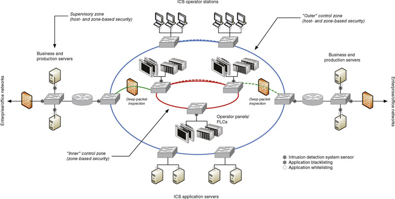
Figure 10.6 Zone-based vulnerability management.
A Security Conduit is established, and the security controls are implemented on the Conduit rather than on the individual assets. As mentioned earlier, industrial firewalls have been deployed to limit network traffic to only that which is allowed including only allowed “functions,” such as the revocation of all engineering and update functions. Intrusion prevention has also been installed in the Conduit to analyze all traffic for authorized use and potential ingress of malware or other attempts to exploit target vulnerabilities.
Maintaining System Availability
An ICS is typically designed to meet very high levels of availability (typically minimum 99.99% or less than 15 min of downtime per year), which means any downtime resulting from a monthly “reboot” required to activate an OS hotfix is considered unacceptable. Redundancy is common at the lowest levels of an ICS architecture, including devices, network interfaces, network infrastructure, and servers. Why then is it so difficult to perform a reboot on a system that is provided with redundant components? Production facilities do not like to invoke redundancy when it is not absolutely necessary, because during the period of time a device is taken out of service, the overall system is left in a nonredundant configuration. Plant management now has to consider the risk of a manufacturing outage due to a known threat (a system operating without redundancy) versus an unknown threat (a cyber event originating from an unpatched system). What do you do if during the routine reboot, the system does not recover? What if you install an AV update and it crashes your server?23
Comprehensive Predeployment Testing
This is the reason that prior to deploying any patch, it is vital to thoroughly test and validate that the updates will not negatively impact the component being patched. The first step involves confirmation from the device vendor or manufacturer that a particular patch is acceptable to install, and equally important, that the patch is tested on an offline system that represents a site’s particular configuration. Some vendors of ICS subsystems have deployed assets that are prohibited from having any security software installed or patches applied for fear that they may impact overall system operation. This may sound irrational, but given the fact that many ICS components have been in operation long before cyber security was a concern, and will remain in operation for many more years to come without undergoing any major system upgrades, this is a problem that must be acknowledged and addressed.
Luckily the implementation of virtualization technologies makes predeployment validation easy for modeling and testing Windows-based assets; but what about network appliances and embedded devices? These generally cannot be deployed in virtual environments, and can represent much greater net risk in terms of consequences resulting from a cyber event. After all, the embedded device is typically the final device that physically connects to the process under control. This leaves organizations with two options, both equally bad: either (1) do not deploy the patches, or (2) do not test the patches before deployment. The problem quickly escalates when you move away from the IT-centric Windows environment to an OT one consisting of a greater percentage of nonstandard embedded devices that do not run standard IT applications and OSes. This is the conundrum that organizations face every day with respect to Patch Management programs and whether or not they are truly a good method of risk management.
Industrial control systems tend to be heterogeneous in nature, comprising components from multiple vendors all integrated through commercial standards of networking (i.e. EtherNet and IP) and data communications (i.e. OPC, SQL, and OLEDB). This means that to minimize any negative impact to operations and system availability, end-users should test ALL patches and updates before deployment.
Automating the Process
Integrated control systems—whether they are SCADA or DCS—are complex and have evolved dramatically since their inception in the 1980s resulting in little consistency from vendor-to-vendor on how their particular application or system is updated. Some vendors may provide complete package updates that require reinstallation of entire applications and suites, while others provide file-level updates and appropriate scripts. Any patch management solution must be able to handle this diversity. It should also be able to handle the management (and hopefully deployment) of patches in the form of firmware updates to the non-Windows components like network appliances and embedded devices (BPCS, SIS, PLC, RTU, IED, etc.). This process must be automated in order to provide a reasonable level of assurance. Automated, not in terms of a “lights out” approach to pushing and installing patches “in the dark,” but rather a process of grouping assets based on criticality, duplicity, and redundancy, and allowing updates to be deployed initially on low-risk assets, then, proceeding to medium-risk assets that may not be redundant, but may be duplicated throughout the architecture (such as the HMI). Finally, critical servers are patched, one at a time, after these critical assets have been tested for compatibility in an off-line environment. The Patch Management solution should also maintain documentation of what updates have deployed to each asset and when. This documentation should align with that established and maintained within each zone as discussed in Chapter 9, “Establishing Zones and Conduits” in terms of both assets and change management procedures.
Finally, do not forget to perform comprehensive backups of the assets prior to performing any patching or updating, as it may be necessary to revert or abort the update if anomalies are detected or incompatibilities arise—up to and including a system not booting. It may also be necessary to abort updates if unplanned external events, like process disturbances, occur that require greater demands in terms of performance and availability of the ICS. When performing firmware updates of embedded devices and appliances, it is important to have equipment on hand, as failed firmware updates can often “brick” the device making it inoperable.
How much security is enough?
In an ideal world, there would be enough budget to implement dozens of network- and host-based security controls, and there would be enough resources to evaluate, test, implement, and operate those controls on an ongoing basis. In reality, budgets are shrinking, and too many security controls can actually be counter-productive and likely detrimental to the overall availability and performance of the ICS.
One of the most important factors to consider when deploying any security control is how it helps to reduce the risk of a cyber event from negatively impacting the ICS and the production assets under its control. In other words, controls should be deployed to reduce specific risk facing an individual organization. Many users are looking for a “play book” of controls that can be deployed on all ICS installations, irrespective of their impact on a particular organization’s cyber risk. In these cases, it often results in not only large budgets, but less than effective protection against cyber threats facing critical infrastructure and industrial facilities in general. A well thought out security program will always balance the “cost of security” versus the “cost of impact.”
Summary
Through the identification and isolation of functional groups, quantifiable security zones can be defined. These zones and the conduits that interconnect them can and should be secured using a variety of tools—including network- and host-based firewalls, network- and host-based intrusion detection and prevention systems (IDS/IPS), application monitoring, anti-virus, and/or application whitelisting (AWL).
In addition to the direct security benefits of these various controls, each also provides useful alerting capabilities that help to improve the situational awareness within the ICS. The information collected from these and other devices can be used to identify and establish baseline behavior, and thereafter to detect exceptions and anomalies (see Chapter 11, “Exception, Anomaly, and Threat Detection”). Logs and events from these zone security measures are also useful for overall activity and behavior monitoring (see Chapter 12, “Security Monitoring of Industrial Control Systems”). A solid defense-in-depth approach offers a balanced approach to not only threat prevention but also threat detection that can be used to provide early response, incident containment, and impact control.
..................Content has been hidden....................
You can't read the all page of ebook, please click here login for view all page.