
Chapter 4. Industrial Network Protocols
Information in this Chapter:
• Overview of Industrial Network Protocols
• Modbus
• ICCP/TASE.2
• DNP3
• OLE for Process Control
• Other Industrial Network Protocols
• AMI and the Smart Grid
Understanding how industrial networks operate requires a basic understanding of the underlying communications protocols that are used, where they are used, and why. There are many highly specialized protocols used for industrial automation and control, most of which are designed for efficiency and reliability to support the economic and operational requirements of large distributed control systems. Similarly, most industrial protocols are designed for real-time operation to support precision operations.
Unfortunately, this means that most industrial protocols forgo any feature or function that is not absolutely necessary, for the sake of efficiency. Even more unfortunate is that this often includes security features such as authentication and encryption, both of which require additional overhead. To further complicate matters, many of these protocols have been modified to run over Ethernet and Internet Protocol (IP) networks in order to meet the evolving needs of business, potentially exposing these vulnerable protocols to attack.
Overview of Industrial Network Protocols
Industrial Network Protocols are often referred to generically as SCADA and/or fieldbus protocols. SCADA protocols are primarily used for the communication of supervisory systems, whereas fieldbus protocols are used for the communication of industrial, automated control systems (ICS or IACS). However, most of the protocols discussed have the ability to perform both functions, and so will be referred to here more generically as Industrial Network Protocols.
Industrial Network Protocols are real-time communications protocols, developed to interconnect the systems, interfaces, and instruments that make up an industrial control system. Most were designed initially to communicate serially over RS-232, RS-485, or other serial connections but have since evolved to operate over Ethernet networks using routable protocols such as TCP/IP.
Four common industrial network protocols will be discussed in some depth, others will be touched upon more briefly, and many will not be covered here: there are literally dozens of industrial protocols, developed by specific manufacturers for specific purposes. Modicon Communication Bus (Modbus), Inter Control Center Protocol (ICCP, also known as TASE.2 or Telecontrol Application Service Element-2), Distributed Network Protocol (DNP3), and Object Linking and Embedding for Process Control (OPC) have been selected for more in-depth discussion because they are all widely deployed and they represent several unique qualities that are important to understand within the context of security. These unique qualities include the following:
• Each is used in different (though sometimes overlapping) areas within an industrial network.
• Each provides different methods of verifying data integrity and/or security.
• The specialized requirements of industrial protocols (e.g., real-time, synchronous communication) often make them highly susceptible to disruption.
By understanding the basic principles of how to secure these protocols, it should be possible to assess the risks of other industrial network protocols that are not covered here directly.
Modbus
Modbus is the oldest and perhaps the most widely deployed industrial control communications protocol. It was designed in 1979 by Modicon (now part of Schneider Electric) that invented the first Programmable Logic Controller (PLC). Modbus has been widely adopted as a de facto standard and has been enhanced over the years into several distinct variants.
Modbus’ success stems from its relative ease of use: it communicates raw messages without restrictions of authentication or excessive overhead. It is also an open standard, is freely distributed, and is widely supported by members of the Modbus Organization, which still operates today.
What It Does
Modbus is an application layer messaging protocol, meaning that it operates at layer 7 of the OSI model. It allows for efficient communications between interconnected assets based on a request/reply methodology. It can be used by extremely simple devices such as sensors or motors to communicate with a more complex computer, which can read measurements and perform analysis and control. To support a communications protocol on a simple device requires that the message generation, transmission, and receipt all require very little processing overhead. This same quality also makes Modbus suitable for use by PLCs and RTUs to communicate supervisory data to a SCADA system.
Because Modbus is a layer 7 protocol, it can operate independently of underlying network protocols, and it has allowed Modbus to be easily adapted to both serial and routable network architectures.
How It Works
Modbus is a request/response protocol using only three distinct Protocol Data Units (PDUs): Modbus Request, Modbus Response, and Modbus Exception Response, as illustrated in Figure 4.1. 1
1.The Modbus Organization, Modbus Application Protocol Specification V1.1b. < http://www.modbus.org/docs/Modbus_Application_Protocol_V1_1b.pdf>, December 2006 (cited: November 24, 2010).
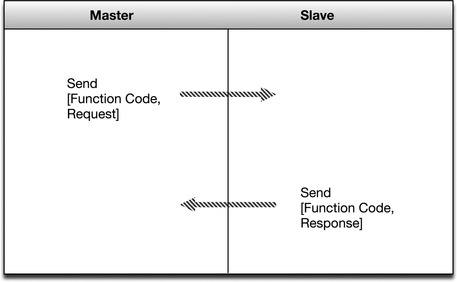
Each device communicating via Modbus must be assigned a unique address. A command is addressed to a specific Modbus address, and while other devices may receive the message, only the addressed device will respond.
A session begins with the transmission of an initial Function Code and a Data Request within a Request PDU. The receiving device responds in one of two ways. If there are no errors, it will respond with a Function Code and Data Response within a Response PDU. If there are errors, the device will respond with an Exception Function Code and Exception Code within a Modbus Exception Response.
Function Codes and Data Requests can be used to perform a wide range of commands. Some examples of Modbus commands include the following:
Variants
The popularity of Modbus has led to the development of several variations to suit particular needs. These include Modbus RTU and Modbus ASCII, which support binary and ASCII transmissions over serial buses, respectively. Modbus TCP is a variant of Modbus developed to operate on modern networks using the IP. Modbus Plus is a variant designed to extend the reach of Modbus via interconnected busses. 2
2.Ibid.
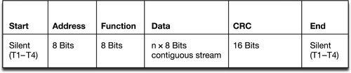
Modbus RTU and Modbus ASCII
These similar variants of Modbus are used in serial communications, and they are the simplest of the variants. Modbus RTU (Figure 4.2) uses binary data representation, whereas Modbus ASCII (Figure 4.3) uses ASCII characters to represent data. Each uses a simple message format carried within a PDU, consisting of an address, function code, a payload of data, and a checksum, to ensure the message was received correctly.

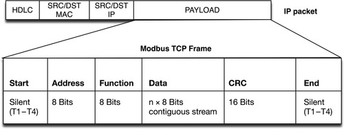
Modbus TCP
Modbus TCP uses Transmission Control Protocol/Internet Protocol (TCP/IP) to transport Modbus commands and messages over modern routable networks. Early implementations of Modbus TCP abandoned the Modbus checksum, relying on the checksum of the underlying TCP/IP protocol, whereas most current Modbus TCP implementations include the original Modbus checksum within the TCP/IP payload, as shown in Figure 4.4.
Modbus Plus or Modbus+
Modbus Plus is proprietary to Modicon, which sends embedded Modbus messages over an RS-485 communication link. Modbus Plus supports some interesting features, including Modbus bridging to allow multiple buses to interconnect, extending the number of supported nodes indefinitely.
Where It Is Used
Modbus is typically deployed between PLCs and HMIs, or between a Master PLC and slave devices such as PLCs, HMIs, Drivers, Sensors, I/O devices, etc., as shown in Figure 4.5. Typically up to 247 devices are supported in a single, non-bridged bus.
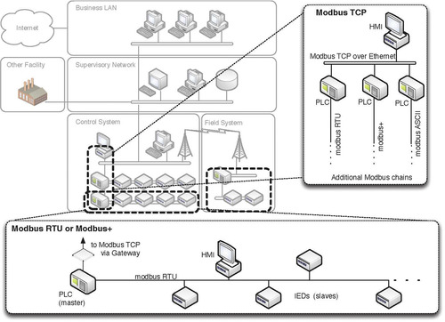
A common deployment uses Modbus on TCP/IP within a SCADA DMZ or Supervisory LAN, where master HMIs provide a central management capability to a number of Master PLCs, each of which may connect serially over a bus topology to a number of PLCs and/or HMIs, responsible for a distinct control loop.
Security Concerns
Modbus represents several security concerns:
• Lack of authentication. Modbus sessions only require the use of a valid Modbus address and valid function code. One can be easily guessed or spammed, whereas the other is easily obtainable information.
• Lack of message checksum (Modbus TCP only). A spoofed command is even easier over some implementations of Modbus TCP, as the checksum is generated at the transmission layer, not the application layer.
• Lack of broadcast suppression (serial Modbus variants only). All serially connected devices will receive all messages, meaning a broadcast of unknown addresses can be used for effective denial of service (DoS) to a chain of serially connected devices.
• Programmability. By far, the most dangerous quality of Modbus—which is shared with many industrial protocols—is that it is intentionally designed to program controllers, and could be used to inject malicious logic into an RTU or PLC.
Security Recommendations
Modbus, like many industrial control protocols, should only be used to communicate between sets of known devices, using expected function codes, and as such it is easily monitored by establishing clear enclaves and by baselining acceptable behavior. For more information about creating whitelists, this topic is discussed in detail in Chapter 8, “Exception, Anomaly, and Threat Detection.”
Some specific examples of Modbus messages that should be of concern include the following:
• Modbus TCP packets that are of wrong size or length.
• Function codes that force slave devices into a “listen only” mode.
• Function codes that restart communications.
• Function codes that clear, erase, or reset diagnostic information such as counters and diagnostic registers.
• Function codes that request information about Modbus servers, PLC configurations, or other need-to-know information.
• Traffic on TCP port 502 that is not Modbus or is using Modbus over malformed protocol(s).
• Any message within an Exception PDU (i.e., any Exception Code).
• Modbus traffic from a server to many slaves (i.e., a potential DoS).
• Modbus requests for lists of defined points and their values (i.e., a configuration scan).
• Commands to list all available function codes (i.e., a function scan).
A SCADA Intrusion Detection System (SCADA-IDS) or SCADA Intrusion Prevention System (SCADA-IPS) can be easily configured to monitor for these activities using Modbus signatures such as those developed and distributed by Digital Bond. In more critical areas, an application-aware firewall, industrial protocol filter, or Application Data Monitor may be required to validate Modbus sessions and ensure that Modbus has not been “hijacked” and used for covert communication, command, and control (i.e., the underlying TCP/IP session on port 502 has not been altered to hide additional communications channels within otherwise normal-looking Modbus traffic). This is discussed in detail in Chapter 7, “Establishing Secure Enclaves.”
Caution
SCADA-IPS devices are able to actively block suspect traffic by dropping packets or resetting TCP connections. Any SCADA-IPS devices should be configured to alert on events, rather than block (i.e., operate in IDS mode rather than active IPS mode), as a false positive that blocks a Modbus command could cause an unintentional failure within the control system.
ICCP/TASE.2
The Inter Control Center Protocol (also known as TASE.2 or IEC60870-6, but more commonly referred to as ICCP) is a protocol designed for communication between control centers within the energy industry. Unlike Modbus, which was designed for serial command requests, ICCP was designed for bidirectional Wide Area Network (WAN) communication between a utility control center and other control centers, power plants, substations, and even other utilities.
Because many custom and proprietary protocols are used by asset vendors, a common protocol was needed to allow for reliable and standardized data exchange between control centers—especially between control centers that are operated by different owners, produce different products, or perform different operations. Basically, standardization became necessary to support the unique business and operational requirements of industry, especially the electrical utilities that require careful load balancing within a bulk system operated by many disparate facilities. For example, in North America, the division of utilities among several responsible regional entities requires a means of sharing information between utilities as well as the regional entity. Similarly, national and global energy markets require real-time information exchange for load distribution and trading that spans the boundaries of individual utilities.
A working group was formed in 1991 to develop and test a standardized protocol and to submit the specification to the IEC. The initial protocol was called ELCOM-90, or Telecontrol Application Service Element-1 (TASE.1). TASE.1 evolved into TASE.2, which is the most commonly used form of ICCP. 3
3.J.T. Michalski, A. Lanzone, J. Trent, S. Smith, SANDIA Report SAND2007-3345: Secure ICCP Integration Considerations and Recommendations, Sandia National Laboratories, Albuquerque, New Mexico and Livermore, California, June 2007.
What It Does
ICCP is used to perform a number of communication functions between control centers, including the following:
• Establishing a connection.
• Accessing information (read requests).
• Information transmission (such as e-mail messages or energy market information).
• Notifications of changes, alarms, or other exception conditions.
• Configuration of remote devices.
• Control of remote devices.
• Control of operating programs.
How It Works
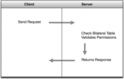
The ICCP protocol defines communication between two control centers using a client/server model. One control center (the server) contains application data and defined functions. Another control center (the client) issues requests to read from the server, and the server responds. Communications over ICCP occur using a common format in order to ensure interoperability.
ICCP support is typically either integrated directly into a control system, provided via a gateway product, or provided as software running on Windows or Unix that can then be installed to perform gateway functions.
Although ICCP is primarily a unidirectional client/server protocol, most modern implementations support both functions, allowing a single ICCP device to function as both a client and a server, and thus supporting bidirectional communication (of a sort) over a single connection.
Although ICCP can operate over essentially any network protocol, including TCP/IP, it is commonly implemented using ISO transport on top of TCP port 102, as defined in RFC 1006. ICCP is effectively a point-to-point protocol due to the use of a “bilateral table” that explicitly defines an agreement between two control centers connected with an ICCP link, as shown in Figure 4.6. The bilateral table is essentially an access control list that identifies which data elements a client can access. The permissions defined within the bilateral tables in the server and the client are the authoritative control over what is accessible to each control center. In addition, the entries in the bilateral tables must match on both the client and the server, ensuring that the permissions are agreed upon by both centers (remembering that ICCP is used to interconnect to other organizations in addition to internal WAN links to substations). 4
4.Ibid.
Where It Is Used
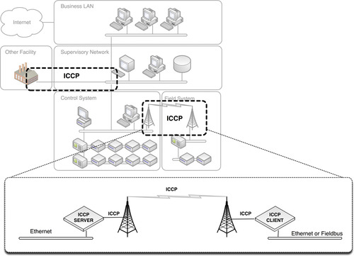
ICCP is widely used between control system enclaves and between distinct control centers, as shown in Figure 4.7, for example, between two electric utilities, between two control systems within a single electric utility, between a main control center and a number of substations, etc.
Security Concerns
Like Modbus, ICCP represents several security concerns. ICCP is susceptible to spoofing, session hijacking, and any number of attacks made possible because of:
• Explicitly defined trust relationships. The exploitation of bilateral tables could directly compromise security of ICCP servers and clients.
• Accessibility. ICCP is a Wide Area Protocol making it highly accessible and susceptible to many attacks including DoS attacks.
The limited security mechanisms within ICCP are configured on the ICCP Master station, meaning that the successful breach of the Master through a Man-in-the-Middle (MITM) or other attack opens the entire communication session up to manipulation.
Security Improvements over Modbus
ICCP offers several improvements over more basic fieldbus protocols such as Modbus, including the following:
Security Recommendations
Secure ICCP variants should be used wherever possible. There are several known vulnerabilities with ICCP that are reported by ICS-CERT. Because there are known exploits in the wild and ICCP is a WAN protocol, proper penetration testing and patching of ICCP servers and clients is recommended.
Extreme care should be taken in the definition of the bilateral table. The bilateral table is the primary enforcement of policy and permissions between control centers and malicious commands issued via ICCP could directly alter or otherwise impact control center operations.
In addition, ICCP clients and servers should be isolated into a unique enclave consisting only of authorized client/server pairs (multiple enclaves can be defined for devices communicating to multiple clients), and the enclave(s) should be thoroughly secured using standard defense-in-depth practices, including a firewall and/or IDS system that enforces strict control over the type, source, and destination of traffic over the ICCP link.
Many malicious behaviors can be detected through monitoring the ICCP link, including the following:
• Intruders gaining unauthorized access to the control center network, via overlooked access points such as dial-up connections to partner or vendor networks.
• Insider threats, including unauthorized information access and transmission, alteration of secure configurations, or other malicious actions can be the result of a physical security breach within a control center, or of a disgruntled employee.
• A DoS attack resulting from repeated information requests (“spamming”) that utilize the server’s available resources and prevent legitimate operation of the ICCP link.
• Malware infecting the ICCP server or other devices could be used to exfiltrate sensitive information for purposes of sabotage (e.g., theft of command function codes), financial disruption (e.g., alteration of energy metrics used in trading), or various other malicious intents.
• Interception and modification of ICCP messages (i.e., MITM) attacks.
Monitoring of ICCP protocol functions can also detect suspicious or malicious behavior, such as
• Function “read” codes that could be used to exfiltrate protected information.
• Function “write” codes that could be used to manipulate client or server operations.
• Traffic on TCP port 102 that is not ICCP.
• ICCP traffic that is not sourced by and destined to defined ICCP servers or clients.
A SCADA-IDS or SCADA-IPS can be easily configured to monitor for these activities. Digital Bond, a security research team funded by the Department of Energy, has Snort compatible IDS signatures and preprocessors to detect a variety of ICCP-related security events. Again, in more critical areas, an application-aware firewall, industrial protocol filter, or Application Data Monitor may be required to validate ICCP sessions and ensure that ICCP or the underlying RFC-1006 connection have not been “hijacked” and that messages have not been manipulated or falsified.
Caution
Any SCADA-IPS devices should be configured with caution and should only alert on events, rather than block them (i.e., operate in IDS mode rather than active IPS mode), as a false positive that blocks an ICCP command could cause an unintentional failure within the control system.
DNP3
DNP3 began as a serial protocol designed for use between master control stations and slave devices or “outstations,” as well as for use between RTUs and IEDs within a control station. Like most control system protocols, DNP3 was extended to work over IP, encapsulated in TCP or UDP packets, in order to make remote RTU communications more easily accessible over modern networks.
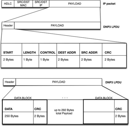
One distinction of DNP3 is that it is very reliable, while remaining efficient and well suited for real-time data transfer. It also utilizes several standardized data formats and supports time-stamped (and time-synchronized) data, making real-time transmissions more efficient and thus even more reliable. Another reason that DNP3 is considered highly reliable is due to the frequent use of CRC checks—a single DNP3 frame can include up to 17 CRCs: one in the header and one per data block within the payload (see the section “How it Works”). There are also optional link-layer acknowledgments for further reliability assurance, and—of particular note—variations of DNP3 that support link-layer authentication as well. Because all of this is done within the link-layer frame, it means that additional network-layer checks may also apply if DNP3 is encapsulated for transport over Ethernet.
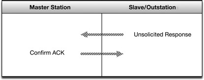
Unlike Modbus and ICCP, DNP3 is both bidirectional (supporting communications from both Master to Slave and from Slave to Master) and supports exception-based reporting. It is therefore possible for a DNP3 outstation to initiate an unsolicited response, in order to notify the Master of an event outside of the normal polling interval (such as an alarm condition).
What It Does
Like the other ICS protocols that have been discussed, DNP3 is primarily used to send and receive messages between control system devices—only in the case of DNP3, it also does it with a high degree of reliability. Assuming that the various CRCs are all valid, the data payload is then processed. Again, the payload is very flexible and can be used to simply transfer informational readings, or it can be used to send control functions, or even direct binary or analog data for direct interaction with devices such as Remote Terminal Units (RTUs), as well as other analog devices such as IEDs.
As mentioned previously, both the link-layer frame (or LPDU) header and the data payload contain CRCs, and the data payload actually contains a pair of CRC octets for every 16 data octets. This provides an exceptional degree of assurance that any communication errors will be detected. If any errors are detected, DNP3 will retransmit the errored frames. In addition to frame integrity, there are also physical layer integrity issues, and it remains possible that a correctly formed and transmitted frame will not arrive at its destination. To overcome this risk, DNP3 uses an additional link layer confirmation. When link layer confirmation is enabled, the DNP3 transmitter (source) of the frame requests that the receiver (destination) confirms the successful receipt of the frame. If a requested confirmation is not received, the link layer will retransmit the frame. This confirmation is optional because although it increases reliability, it adds overhead that directly impacts the efficiency of the protocol. In real-time environments, this added overhead may not be appropriate. 5
5.The DNP Users Group, DNP3 Primer, Revision A. < http://www.dnp.org/About/DNP3%20Primer%20Rev%20A.pdf>, March 2005 (cited: November 24, 2010).
Once a successful and (if requested) confirmed frame arrives, the frame is processed. Each frame consists of a multipart header and a data payload. The header is significant as it contains a well-defined function code, which can tell the recipient whether it should confirm, read, write, select a specific point, operate a point (initiate a change to a point), directly operate a point (both selecting and changing a point in one command), or directly operate a point without acknowledgment. 6
6.G.R. Clarke, Deon Reynders Practical Modern SCADA Protocols: DNP3, 60870.5 and Related Systems, Newnes, Oxford, UK and Burlington MA, 2004.
These functions are especially powerful when considering that the data payload of the DNP3 frame supports analog data, binary data, files, counters, and other types of data objects. At a high level, DNP3 supports two kinds of data, referred to as class 0 or static data (data that represents a static value or point reading) and event data (data that represents a change, some sort of activity, or an alarm condition). Event data is rated by priority from class 1 (highest) to class 3 (lowest). The differentiation of static and event data, as well as the classification of event data allows DNP3 to operate more efficiently by allowing higher-priority information to be polled more frequently, for example, or to enable or disable unsolicited responses by data type. The data itself can be binary, analog input or output, or a specific control output. 7
7.The DNP Users Group, DNP3 Primer, Revision A. < http://www.dnp.org/About/DNP3%20Primer%20Rev%20A.pdf>, March 2005 (cited: November 24, 2010).
How It Works
DNP3 provides a method to identify the remote device’s parameters and then use message buffers corresponding to event data classes 1 through 3 in order to identify incoming messages and compare them to known point data. In this way, the master device is only required to retrieve new information resulting from a point change or change event.
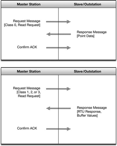
Initial communications are typically a class 0 request from the Master to an Outstation, used to read all point values into the Master database. Subsequent communications will typically either be direct poll requests for a specific data class from the Master; unsolicited responses for a specific data class from an outstation; control or configuration requests from the Master to an RTU, and subsequent periodic class 0 polls. When a change occurs on an outstation, a flag is set to the appropriate data class. The Master station is then able to poll only those outstations where there is new information to be reported.
This is a huge departure from constant data polling that can result in improved responsiveness and much more efficient data exchange. The departure from a real-time polling mechanism does require time synchronization, however, because the time between a change event and a successful poll/request sequence is variable. Therefore, all responses are time-stamped, so that the events between polls can be reconstructed in the correct order.
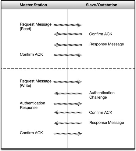
Communication is initiated by the Master to the Slave, or in the case of unsolicited responses (alarms) from the slave to the master, as shown in Figure 4.8. Because DNP3 operates bidirectionally and supports unsolicited responses, as shown in Figure 4.9, each frame requires both a source address and a destination address so that the recipient device knows which messages to process, and so that it knows which device to return responses to. Although the addition of a source address (remember that in the other purely Master/Slave protocols, there is no need for a source address as the originating device is always the master) does add some overhead, it does so for the sake of dramatically increased scalability and functionality; as many as 65,520 individual addresses are available within DNP3, and any one of them can initiate communications. An address equals one device (every DNP3 device requires a unique address), although there are reserved DNP3 addresses, including one for broadcast messages (which will be received and processed by all connected DNP3 devices). 8
8.Ibid.
Secure DNP3
Secure DNP3 is a DNP3 variant that adds authentication to the response/request process, as shown in Figure 4.10. Authentication is issued as a challenge by the receiving device. A challenge condition occurs upon session initiation (when a master station initiates a DNP3 session with an outstation), after a preset period of time (the default is 20 minutes), or upon a critical request (it is possible to know which requests are critical because the data types and functions of DNP3 are well defined) such as writes, selects, operates, direct operates, starts, stops and restarts, etc. 9
9.Digitalbond SCADAPEDIA, Secure DNP3. < http://www.digitalbond.com/wiki/index.php/Secure_DNP3>, August 2008 (cited: November 24, 2010).
Authentication occurs using a unique session key, which is hashed together with message data from the sender and from the challenger. The result is an authentication method that at once verifies authority (checksum against the secret key), integrity (checksum against the sending payload), and pairing (checksum against the challenge message). In this way, it is very difficult to perform data manipulation or code injection, or to spoof or otherwise hijack the protocol. 10
10.Ibid.
The DNP3 layer 2 frame provides the source, destination, control, and payload, and can operate over a variety of application layers including TCP/IP (typically using TCP port 20000 or UDP port 20000). The function codes are resident within the CNTRL bytes in the DNP3 frame header, as shown in Figure 4.11.
Where It Is Used
As shown in Figure 4.12, DNP3 is primarily used between a master control station and an RTU in a remote station, over almost any medium including wireless, radio, and dial-up. However, DNP3 is also widely used between RTUs and IEDs. As such it competes directly with the Modbus protocols within several areas of the control system.
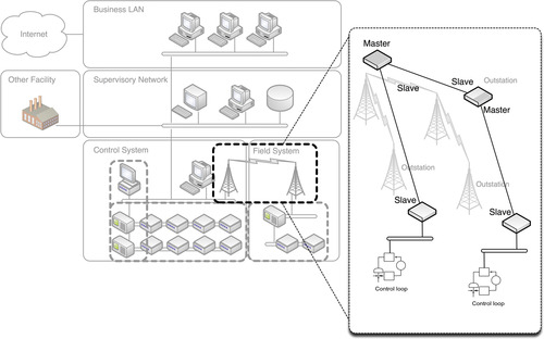
Unlike Modbus, however, DNP3 is well suited for hierarchical and aggregated point-to-multipoint topologies in addition to the linear point-to-point and serial point-to-multipoint topologies that are supported by Modbus. 11
11.The DNP Users Group, DNP3 Primer, Revision A. < http://www.dnp.org/About/DNP3%20Primer%20Rev%20A.pdf>, March, 2005 (cited: November 24, 2010).
Security Concerns
While much attention is given to the integrity of the data frame, there is no authentication or encryption inherent within DNP3 (although there is within Secure DNP3). Because of the well-defined nature of DNP3 function codes and data types, it then becomes relatively easy to manipulate a DNP3 session.
Also, while DNP3 does include security measures, the added complexity of the protocol increases the chances of vulnerability. As of this writing, there are several known vulnerabilities with DNP3 that are reported by ICS-CERT. Because there are known exploits in the wild and DNP3 is a heavily deployed protocol, proper penetration testing and patching of DNP3 interconnections is recommended.
Some examples of realistic hacks against DNP3 include the use of MITM attacks to capture addresses, which can then be used to manipulate the system. Examples include the following:
• Turning off unsolicited reporting to stifle alarms. 12
12.A.B.M. Omar Faruk, Testing & Exploring Vulnerabilities of the Applications Implementing DNP3 Protocol, KTH Electrical Engineering, Stockholm, Sweden, June 2008.
• Spoofing unsolicited responses to the Master to falsify events and trick an operator into taking inappropriate actions.
• Performing a DoS attack through the injection of broadcasts, creating storm behavior within the full extent of the DNP3 system.
• Manipulating the time synchronization data, resulting in synchronization loss and subsequent communication errors.
• Manipulating or eliminating confirmation messages forcing a state of continuous retransmission.
• Issuing unauthorized stops, restarts, or other functions that could disrupt operations.
Security Recommendations
Because a secure implementation of DNP3 exists, the primary recommendation is to implement only Secure DNP3. However, it may not always be possible due to varying vendor support and other factors. In these cases, secure use of the transport layer protocol is advised, such as the use of Transport Layer Security (TLS). In other words, treat your encapsulated DNP3 traffic as highly sensitive information and use every TCP/IP security best practice to protect it.
As always, DNP3 masters and outstations should be isolated into a unique enclave consisting only of authorized devices (multiple enclaves can be defined for devices communicating to multiple clients, or for hierarchical Master/Slave pairs), and the enclave(s) should be thoroughly secured using standard defense-in-depth practices, including a firewall and/or IDS system that enforces strict control over the type, source, and destination of traffic over the DNP3 link.
Many threats can be detected through monitoring the DNP3 session, and looking for specific function codes and behaviors, including the following:
• Use of any non-DNP3 communication on a DNP3 Port (TCP and UDP Port 20000).
• Use of configuration function code 23 (Disable Unsolicited Responses).
• Use of control function codes 4, 5, or 6 (Operate, Direct Operate, and Direct Operate without Acknowledgment).
• Use of application control function 18 (Stop Application).
• Multiple, unsolicited responses over time (Response Storm).
• Any unauthorized attempt to perform an action requiring authentication.
• Any authentication failures.
• Any DNP3 communication sourced from or destined to a device that is not explicitly identified as a DNP3 master or slave device.
As with other industrial protocols, SCADA-IDS or SCADA-IPS can be easily configured to monitor for these activities, while an application-aware firewall or Application Data Monitor may be required to validate DNP3 sessions.
Caution
Any SCADA-IPS devices should be configured with caution, and should only alert on events, rather than block them (i.e., operate in IDS mode rather than active IPS mode), as a false positive that blocks a valid DNP3 function code could cause an unintentional failure within the control system.
OLE for Process Control
OPC is not an industrial network protocol, but rather an operational framework for the communication of Windows-based process control systems using Microsoft’s Object Linking and Embedding (OLE) protocol, which itself heavily utilizes additional communications protocols such as Remote Procedure Call (RPC). That is, OPC is a suite of protocols that collectively enable process control systems to communicate using some of the underlying networking capabilities of Windows.
What It Does
OPC differs from the other fieldbus protocols discussed in this chapter in that its primary function is to interconnect other distributed control systems with Windows hosts, typically connected via an Ethernet TCP/IP network. OPC is an implementation of OLE for Process Control Systems. Originally OPC was Distributed Component Object Model (DCOM) based, and many OPC systems in use today use DCOM, although OPC has more recently been updated to use an object-oriented protocol called OPC-Unified Architecture (OPC-UA). 13
13.The OPC Foundation OPC Task Force, OPC Overview Version 1.0. < http://www.opcfoundation.org/Archive/c218e7b5-4e00-4f95-82ba-7da07eb17883/General/OPC%20Overview%201.00.pdf>, October 27, 1998 (cited: November 24, 2010).
OPC provides a common communications interface between diverse industrial control systems and products by leveraging Microsoft’s DCOM communications API, reducing the need for device-specific drivers. In place of specific communications drivers for each device, simple device drivers could be written to interface with OPC. The use of OPC therefore minimized driver development and allowed for better optimization of core OPC interfaces. 14
14.Ibid.
OPC’s strengths and weaknesses come from its foundation, which is based upon Microsoft’s OLE protocol. OLE is used extensively in Office document generation and is used to embed a common data set in both a Word file and an Excel spreadsheet, for example. This not only allows OPC-connected devices to communicate and interact with minimal operator feedback (as in the case of the Office documents) but also presents significant security challenges. 15
15.Digital Bond, British Columbia Institute of Technology, and Byres Research. OPC Security White Paper #2: OPC Exposed (Version 1-3c), Byres Research, Lantzville, BC and Sunrise, FL, November 13, 2007.
How It Works
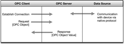
OPC works in a client/server manner, where a client application calls a local process, but instead of executing the process using local code, the process is executed on a remote server. The remote process is linked to the client application and is responsible for providing the necessary parameters and functions to the server, over an RPC.
In other words, the stub process is linked to the client, but when a function is performed, the process is performed remotely, on the server. The server RPC functions then transmit the requested data back to the client computer. Finally, the client process receives the data over the network, provides it to the requesting application, and closes the session, as shown in Figure 4.13.
In Windows systems, the requesting application typically loads RPC libraries at run-time, using a Windows dynamic link library (DLL). 16
16.Microsoft Corporation, RPC Protocol Operation. < http://msdn.microsoft.com/en-us/library/ms818824.aspx> (cited: November 4, 2010).
OPC is more complex than previous client/server industrial network protocols because of this interaction with the calling application and the underlying DCOM architecture. It interacts with various aspects of the host operating system, tying it closely to other host processes and exposing the protocol to a very broad attack surface. OPC also inherently supports remote operations (ROPs) that allow OPC to perform common control system functions. 17
17.European Organization for Nuclear Research (CERN), A Brief Introduction to OPC™ Data Access. < http://itcofe.web.cern.ch/itcofe/Services/OPC/GeneralInformation/Specifications/RelatedDocuments/DASummary/DataAccessOvw.html>, November 11, 2000 (cited: November 29, 2010).
OPC-UA and OPC-XI
The OPC-UA and the OPC Express Interface (XI) are newer variations of OPC that break away from OPC Classic’s dependence upon OLE. OPC-UA and OPC-XI preserve the functionality of earlier OPC implementations, while introducing new capabilities including stronger authentication services, encryption, and new transport mechanisms, including SOAP over HTTPS, and binary encoding to improve performance over XML, which has relatively high overhead. 18
18.Digital Bond, British Columbia Institute of Technology, and Byres Research, OPC Security White Paper #1 Understanding OPC and How It Is Deployed (Version 1-3b), Byres Research, Lantzville, BC and Sunrise, FL, July 27, 2007.
OPC-UA and OPC-XI represent strong improvements over legacy OPC implementations in terms of security. However, legacy OPC systems remain heavily deployed.
Where It Is Used
OPC is primarily a SCADA protocol, and it is used within many areas of industrial networks, including data transfer to data historians, data collection within HMIs, and other supervisory controls, as shown in Figure 4.14. OPC is a Windows interconnection, and so all communications occur either between Windows-based devices, or via OPC gateways that translate the RPC to the native fieldbus format. Unfortunately, OPC is also widely used within an industrial system’s business network, including connections to corporate intranets, and even the Internet. 19 Because of the common use of OLE, RPC, and DCOM protocols within OPC, this opens the SCADA environment to a very broad attack surface.
19.Ibid.
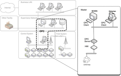
Typically, OPC will be used “upstream” of fieldbus protocols, acting as a gateway between these protocols and Windows-based computing networks.
Security Concerns
OPC’s use of DCOM and RPC makes it highly vulnerable to attack, as it is subject to the same vulnerabilities as the more ubiquitously used OLE. In addition, OPC is rooted in the Windows operating system (OS) and is therefore susceptible to attack through exploitation of any vulnerability inherent to the OS. 20
20.Digital Bond, British Columbia Institute of Technology, and Byres Research. OPC Security White Paper #2: OPC Exposed (Version 1-3c), Byres Research, Lantzville, BC and Sunrise, FL, November 13, 2007.
OPC and related control system vulnerabilities are available only to authorized members of ICS-CERT; however, many OLE and RPC vulnerabilities exist and are well known. Because of the difficulties involved in patching production systems within an industrial network (see Chapter 6, “Vulnerability and Risk Assessment”), many of these vulnerabilities are still in place, even if there is an available patch from Microsoft.
Also, because OPC is supported on Windows, many basic host security concerns apply. Many OPC hosts utilize weak authentication, and passwords are often weak when authentication is enforced. Many systems support additional Windows services that are irrelevant to SCADA systems, resulting in unnecessary processes, which often correspond to open ports. These issues open the OPC system up to a broader attack surface. Inadequate or nonexistent logging exacerbates this by providing insufficient forensic detail should a breach occur, as Windows 2000/XP auditing settings do not record DCOM connection requests by default. 21
21.Ibid.
In other words, unlike the simple and single-purpose protocols discussed until now, OPC must be treated as a larger system, according to modern OS and network security practices. Given OPC’s reliance on Microsoft authentication mechanisms, weak passwords are among the most critical vulnerabilities that can undermine the security of an OPC server. Inadequate logging is also a primary concern, as by default, Windows 2000/XP auditing settings do not record DCOM connection requests, SMB log-ins, or attempts to access system objects. 22
22.Ibid.
Other security concerns of OPC include the following:
• Legacy authentication services. Because systems within industrial networks are difficult to upgrade (due to limited maintenance windows, interpretability concerns, and other factors), insecure authentication mechanisms remain in use. For example, Windows 2000 LanMan (LM) and NT LanMan (NTLM) authentication mechanisms are still used by default in many systems. These and other legacy authentication mechanisms may be vulnerable and susceptible to exploitation. 23
23.Ibid.
• RPC vulnerabilities. Because OPC uses RPC, it is susceptible to all RPC-related vulnerabilities, including several vulnerabilities that are exposed prior to authentication. Exploitation of underlying RPC vulnerabilities could result in arbitrary code execution, or DoS. 24
24.Ibid.
• Unnecessary ports and services. OPC supports other network protocols other than TCP/IP, including NetBIOS Extended User Interface (NetBEUI), Connection Oriented NetBIOS over InterNetwork packet Exchange (IPX), and Hyper Text Transport Protocol (HTTP) Internet services. 25
25.Ibid.
• OPC Server Integrity. It is possible to create a rogue OPC server and to use that server for disruption of service, DoS, information theft through bus snooping, or the injection of malicious code. 26
26.Ibid.
Security Recommendations
OPC-UA or OPC-XI should be used where possible.
Regardless of the OPC variation used (Classic, UA, or XI), all unnecessary ports and services should be removed or disabled from the OPC server. This includes any and all irrelevant applications, and all unused network protocols. All unused services may introduce vulnerabilities to the system that could result in a compromise of the Windows host, and therefore the OPC network. 27
27.Ibid.
OPC servers should be isolated into a unique enclave consisting only of authorized devices, and the enclave(s) should be thoroughly secured using standard defense-in-depth practices, including a firewall and/or IDS/IPS system that enforces strict control over the type, source, and destination of traffic to and from the OPC enclave.
Because OPC is primarily used in a supervisory capacity, IPS can be considered in place of IDS, understanding that an IPS may block SCADA traffic and result in a lack of visibility into control system operations. If information loss will be damaging to the control process or detrimental to business operations, use only IDS.
Many threats can be detected through monitoring OPC networks and/or OPC servers (server activity can be monitored through the collection and analysis of Windows logs), and looking for specific behaviors, including the following:
• The use of non-OPC ports and services initiated from the OPC server.
• The presence of known OPC (including underlying OLE RPC and DCOM) exploits.
• OPC services originating from unknown OPC servers (indicating the presence of a rogue server).
• Failed authentication attempts or other authentication anomalies on the OPC server.
• Successful authentication attempts on the OPC server from unknown or unauthorized users.
Most commercially available IDS and IPS devices support a wide range of detection signatures for OLE and RPC and therefore can also detect many of the underlying vulnerabilities of OPC. Similarly, most open-source and commercial log analysis and threat detection tools are capable of collecting and assessing Windows logs.
Tip
OPC-UA and OPC-XI, as well as certain OPC Classic vulnerabilities, may require the use of a SCADA-IDS or SCADA-IPS rather than an enterprise IDS or IPS. Enterprise devices typically detect exploits via inspection of OLE, RPC, and DCOM and may not be able to detect all threats targeting OPC. In some cases, enterprise IDS and IPS devices may be adapted to detect a wider range of OPC threats, using Snort® compatible preprocessors and detection signatures available from Digital Bond.
Other Industrial Network Protocols
There are dozens of industrial protocols—more than can be covered in even cursory detail within this book. Several warrant mention, as they introduce new concepts and/or concerns regarding industrial network security. These include Ethernet/IP, Profibus, EtherCAT, Ethernet Powerlink, and SERCOS III.
Ethernet/IP
Ethernet/IP uses standard Ethernet frames (ethertype 0x80E1) in conjunction with the Common Industrial Protocol (CIP) suite to communicate with nodes. Communication is typically client/server, although an “implicit” mode is supported to handle real-time requirements. Implicit mode uses connectionless transport—specifically the User Datagram Protocol (UDP) and multicast transmissions—to minimize latency and jitter.
Note
The “IP” in Ethernet/IP derives from “Industrial Protocol” and not “Internet Protocol,” because of the use of the Common Industrial Protocol (CIP). Similarly, the acronym “CIP” meaning “Common Industrial Protocol” should not be confused with “Critical Infrastructure Protection” of NERC CIP.
The CIP uses object models to define the various qualities of a device. There are three types of objects: Required Objects, which define attributes such as device identifiers, routing identifiers, and other attributes of a device such as the manufacturer, serial number, date of manufacture, etc.; Application Objects, which define input and output profiles for devices; and Vendor-specific Objects, which enable vendors to add proprietary objects to a device. Objects (other than vendor-specific objects) are standardized by device type and function, to facilitate interoperability: if one brand of pump is exchanged for another brand, for example, the application objects will remain compatible, eliminating the need to build custom drivers. The wide adoption and standardization of CIP has resulted in an extensive library of device models, which can facilitate interoperability but can also aid in control network scanning and enumeration (see Chapter 6, “Vulnerability and Risk Assessment”).
While the Required Objects provide a common and complete set of identifying values, the Application Objects contain a common and complete suite of services for control, configuration, and data collection that includes both implicit (control) and explicit (information) messaging. 28
28.ODVA, CIP Technology Overview. < http://www.odva.org/Home/ODVATECHNOLOGIES/CIP/CIPTechnologyOverview/tabid/68/Default.aspx>, 2010 (cited: November 24, 2010), Saarbrücken, Germany.
Security Concerns
Ethernet/IP is a real-time Ethernet protocol, and as such it is susceptible to any of the vulnerabilities of Ethernet. Ethernet/IP over UDP is transaction-less and so there is no inherent network-layer mechanism for reliability, ordering, or data integrity checks. The CIP also introduces some specific security concerns, due to its well-defined object model.
The following concerns are specific to Ethernet/IP:
• The CIP does not define any explicit or implicit mechanisms for security.
• The use of common Required Objects for device identification can facilitate device identification and enumeration, facilitating an attack.
• The use of common Application Objects for device information exchange and control can enable broader industrial attacks, able to manipulate a broad range of industrial devices.
• Ethernet/IP’s use of UDP and Multicast traffic—both of which lack transmission control—for real-time transmissions facilitate the injection of spoofed traffic or (in the case of multicast traffic) the manipulation of the transmission path using injected IGMP controls.
Security Recommendations
Because Ethernet/IP is a real-time Ethernet protocol using UDP and IGMP, it is necessary to provide Ethernet and IP-based security at the perimeter of any Ethernet/IP network. It is also recommended that passive network monitoring be used to ensure the integrity of the Ethernet/IP network, ensuring that the Ethernet/IP protocol is only being used by explicitly identified devices and that no Ethernet/IP traffic is originating from an unauthorized, outside source. This can be accomplished using a SCADA-IDS/IPS or other network monitoring device capable of detecting and interpreting the Ethernet/IP protocol.
Profibus
Profibus (Process fieldbus) is a fieldbus protocol that was originally developed in the late 1980s in Germany by the Central Association for the Electrical Industry. Several specialized variants of Profibus exist, including Profibus-DP (Decentralized Periphery) and Profibus-PA (Process Automation). The standardized variant is Profibus-DP, which itself has three common variants: Profibus DP-V0, DP-V1, and DP-V2, each of which represents a minor evolution of capabilities within the protocol. There are also three profiles for Profibus communication: asynchronous, synchronous, and via Ethernet using ethertype 0x8892. Profibus over Ethernet is also called Profinet. 29
29.V.M. Igure, Security assessment of SCADA protocols: a taxonomy based methodology for the identification of security vulnerabilities in SCADA protocols, VDM Verlag Dr. Müller Aktiengesellschaft & Co. KG, 2008.
Profibus is a Master/Slave protocol that supports multiple master nodes through the use of token sharing: when a master has control of the token, it can communicate with its slaves (each slave is configured to respond to a single master). In Profibus DP-V2, slaves can initiate communications to the master or to other slaves under certain conditions. Typically, a master Profibus node is a PLC or RTU, and a slave is sensor, motor, or some other control system device.
Security Concerns
Profibus lacks authentication inherent to many of its functions, allowing a spoofed node to impersonate a master node, which in turn provides control over all configured slaves. A compromised master node or a spoofed master node could also be used to capture the token, inject false tokens, or otherwise disrupt the protocol functions, causing a DoS. A rogue master node could alter clock synchronization to slave devices, snoop query responses (across all masters), or even inject code into a slave node.
Profibus over Ethernet (Profinet) is a real-time Ethernet protocol, and as such it is susceptible to any of the vulnerabilities of Ethernet. When used over the IP, it is also susceptible to any vulnerabilities of IP.
Note
Stuxnet (see Chapter 3, “Introduction to Industrial Network Security”) is an example of Profibus exploitation. Stuxnet compromised PLCs (master Profibus nodes), which were then used to monitor the Profibus and look for specific behaviors associated with frequency controllers. Once the sought-after conditions were detected, Stuxnet then issued commands to the relevant slave nodes to sabotage the process.
Security Recommendations
As with many fieldbus protocols, the inherent lack of authentication and vulnerability of the protocol requires strong isolation of the bus. If Profinet is used, it should be controlled and used only over authenticated and encrypted networks. Monitoring of Ethernet networks for unauthorized or suspicious use of Profinet should be implemented as well, and firewalls and IPS devices should be configured to explicitly deny Profinet outside of well-defined areas.
EtherCAT
EtherCAT is another real-time Ethernet fieldbus protocol, which uses a defined Ethernet ethertype (0x88A4) to transport control systems communications over standard Ethernet networks. To maximize the efficiency of distributed process data communications (which requires only a few bytes per cycle) over Ethernet frames (which vary in size from 46 to 1500 bytes of payload), EtherCAT communicates large amounts of distributed process data with just one Ethernet frame, so that typically only one or two Ethernet frames are required for a complete cycle. Slaves pass the frame(s) to other slaves in sequence, appending its appropriate response, until the last slave returns the completed response frame back. 30
30.The EtherCAT Technology Group, Technical introduction and overview: EtherCAT—the Ethernet Fieldbus. < http://www.ethercat.org/en/technology.html#5>, May 10, 2010 (cited: November 24, 2010).
Security Concerns
EtherCAT is a real-time Ethernet protocol, and as such it is susceptible to any of the vulnerabilities of Ethernet. EtherCAT over UDP is transaction-less and so there is no inherent network-layer mechanism for reliability, ordering or data integrity checks.
As with many real-time Ethernet protocols, EtherCAT is sensitive and highly susceptible to DoS attacks. EtherCAT is easily disrupted via the insertion of rogue Ethernet frames into the network to interfere with time synchronization and is subject to spoofing and MITM attacks due to the lack of bus authentication, requiring the separation of EtherCAT from other Ethernet systems.
Security Recommendations
Because EtherCAT is a real-time Ethernet protocol, it is necessary to provide Ethernet-based security at the perimeter of any EtherCAT network. It is also recommended that passive network monitoring be used to ensure the integrity of the EtherCAT network, ensuring that the EtherCAT protocol is only being used by explicitly identified devices and that no EtherCAT traffic is originating from an unauthorized, outside source. This can be accomplished using a SCADA-IDS/IPS or other network monitoring device capable of detecting and interpreting the EtherCAT protocol. A network monitoring product or probe can also be used to detect Ethernet packets using EtherCAT’s specific ethertype.
Ethernet Powerlink
Ethernet Powerlink uses Fast Ethernet as the basis for real-time transmission of industrial control messages. A master node is used to initiate and synchronize cyclic polling of slave devices, by transmitting a master “Start of Cycle” frame that provides a basis for the network synchronization. The master then polls each station; slaves can only respond if they receive a poll request frame, ensuring that all Master/Slave communications occur in sequence. Slave responses are broadcast, eliminating source address resolution. Because collisions are avoided solely via the carefully controlled request/response cycles, Ethernet Powerlink is best used homogeneously: the introduction of other Ethernet-based systems could disrupt synchronization and cause a failure. 31
31.P. Doyle, Introduction to Real-Time Ethernet II. The Extension: A Technical Supplement to Control Network, vol. 5, Issue 4, Contemporary Control Systems, Inc., Downers Grove, IL, July 2004.
Ethernet Powerlink is often used in conjunction with CANopen, an application layer protocol based on CAN (Controller Area Network). CANopen enables the communication between devices of different manufacturers, and the protocol stacks are widely available including open-source distribution for both Windows and Linux platforms. The open nature of CANopen makes Ethernet Powerlink/CANopen a desirable combination for industrial networks requiring inexpensive solutions in Linux environments. 32
32.Ethernet POWERLINK Standardization Group, CANopen. < http://www.ethernet-powerlink.org/index.php?id=39>, 2009 (cited: November 24, 2010).
Security Concerns
Ethernet Powerlink is a real-time Ethernet protocol, and as such it is susceptible to any of the vulnerabilities of Ethernet. Ethernet Powerlink is designed for use over all IPs, including TCP, UDP, and HTTP, and it is therefore also susceptible to any corresponding IP vulnerabilities.
As with many real-time Ethernet protocols, Ethernet Powerlink is sensitive and highly susceptible to DoS attacks. Ethernet Powerlink is easily disrupted via the insertion of rogue Ethernet frames into the network, requiring the separation of Ethernet Powerlink from other Ethernet systems. The protocol itself is sensitive and highly susceptible to DoS attacks.
Security Recommendations
Because sensitivity of the cyclic polling mechanism requires separation from other non–Powerlink Ethernet services, Ethernet Powerlink implementations will most likely have a clear demarcation from other networks. This demarcation can be leveraged to further isolate the industrial protocol, through the establishment of strong perimeter defenses at these boundaries.
SERCOS III
SERCOS (Serial Real-time Communications System) is a fieldbus specialized for digital motion control. SERCOS III is a real-time Ethernet communication protocol specifically designed for serial communications between PLCs and IEDs, operating at high speeds within closed loops. 33
33.SERCOS International, Technology: Introduction to SERCOS interface. < http://www.sercos.com/technology/index.htm>, 2010 (cited: November 24, 2010).
SERCOS III is a Master/Slave protocol that operates cyclically, using a mechanism in which a single Master Synchronization Telegram is used to communicate to slaves, and the slave nodes are given a predetermined time (again synchronized by the master node) during which they can place their data on the bus. All messages for all nodes are packaged into a Master Data Telegram, and each node knows which portion of the MDT it should read based upon a predetermined byte allocation. 34
34.SERCOS International, Technology: Cyclic Operation. < http://www.sercos.com/technology/cyclic_operation.htm>, 2010 (cited: November 24, 2010).
An interesting addition to SERCOS III is that, although SERCOS dedicates the use of the bus for synchronized real-time traffic during normal cycles, it allows unallocated time within a cycle to be freed up for other network protocols such as IP. This “IP Channel” allows the use of broader network applications from the same device—for example, a web-based management interface that would be accessible to business networks. 35
35.SERCOS International, Technology: Service & IP Channels. < http://www.sercos.com/technology/service_ip_channels.htm>, 2010 (cited: November 24, 2010).
Security Concerns
SERCOS III is a real-time Ethernet protocol, and as such it is susceptible to any of the vulnerabilities of Ethernet. SERCOS III introduces new security concerns through the option to support embedded, open TCP/IP communications. With this option enabled, a compromised RTU or PLC using SERCOS III could be used to launch an in-bound attack into other corporate communications systems, including SCADA and business networks.
Security Recommendations
SERCOS III should be isolated to control loops that require the protocol, and the use of IP channels should be seriously considered and avoided where possible. If IP channels are used, the extent and reach of the IP channel should be enclosed within an explicitly defined enclave consisting of the SERCOS III master node and only those TCP/IP network devices that are absolutely required.
AMI and the Smart Grid
The smart grid is a term encompassing many aspects of modern power transmission. Although smart grid technology might seem irrelevant to many industrial network systems outside of the energy industry, it is discussed briefly here because of its broad reach and vulnerable attack surface. The smart grid is a widely distributed communication network that touches both energy production and transmission systems and many end user networks. Therefore, the smart grid represents an easily accessible network that contains many vectors to many possible targets; once compromised, an attacker could use the network to attack the power utility’s network, or to attack the networks of connected home and/or business networks.
The term “smart grid” is widely used and generally refers to a new generation of energy distribution built around an Advanced Metering Infrastructure (AMI). AMI promises many new features designed to increase the efficiency and reduce the costs of energy distribution. Common AMI features include Remote Meter Reading; Remote Billing; Demand/Response Energy Delivery; Remote Connect/Disconnect; and Remote Payment and Prepayment. 36
36.UCA® International Users Group, AMI-SEC Task Force, AMI System Security Requirements, UCA, Raleigh, NC, December 17, 2008.
At a high level, the smart grid requires coordination among the following systems:
• Bulk Generation Systems
• Transmission Systems
• Distribution Systems
• Customer Information and Management Systems
• Usage and Meter Management Systems
• Billing Systems
• Interconnected network systems, including Neighborhood Area Networks (often using wireless mesh technologies); Metropolitan Area Networks (MANs); Home Area Networks (HANs); and Business Area Networks (BANs)
The smart grid is essentially a large, end-to-end communications system interconnecting power suppliers to power consumers (see Figure 4.15). It is made of highly diverse systems, using diverse protocols and network topologies. Smart grids even introduce new protocols. To support home- and business-based service portals, Smart Metering introduces HAN and BAN protocols, such as Zigbee and HomePNA, as well as power line protocols such as IEC 61334, Control Network Power Line (PL) Channel Specification, and Broadband over Powerline (BPL). Although the data link and application protocols are too numerous to discuss in detail, it is widely accepted that TCP/IP will be leveraged for network-layer communications. 37
37.National Institute of Standards and Technology, NIST Special Publication 1108: NIST Framework and Roadmap for Smart Grid Interoperability Standards, Release 1.0, February 2010.
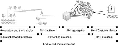
Although these specific protocols will not be discussed within this book, it is important to recognize that the disparate nature of these systems requires that several distinct operational models and several distinct network architectures combine to form a single end-to-end communications path, as illustrated in Figure 4.15. This means that while many distinct smart grid protocols may be used, the smart grid as a whole should be considered as a single, highly accessible communications network that is highly interconnected.
Security Concerns
The security concerns of smart grid are numerous. AMI represents an extremely large network that touches many private networks and is designed for command and control in order to support remote disconnect, demand/response billing, and other features. 38 Combined with a lack of industry-accepted security standards, the smart grid represents significant risk to connected systems that are not adequately isolated. Specific security concerns include the following:
38.UCA® International Users Group, AMI-SEC Task Force, AMI system security requirements, UCA, Raleigh, NC, December 17, 2008.
• Smart meters are highly accessible and therefore require board- and chip-level security in addition to network security.
• Smart grid protocols vary widely in their inherent security and vulnerabilities.
• Smart grids are ultimately interconnected with critical power generation and distribution systems.
• Smart grids represent a target to private hackers (for financial gain or service theft) as well as to more sophisticated and serious attackers (for sociopolitical gain or cyber warfare).
Security Recommendations
The best recommendation for smart grid security at this point is for electric utilities to carefully assess smart grid deployments and to perform risk and threat analysis early in the planning stages, and for the end users who are connected to the smart grid to perform a similar assessment of the system as a potential threat vector into the business (or home) network.
Again, clear delineation, separation of services, and the establishment of strong defense in depth at the perimeters will help to minimize any threat associated with the smart grid. For the smart grid operators, this could represent a challenge (especially in terms of security monitoring) due to the broad scale of smart grid deployments, which could contain hundreds of thousands or even millions of intelligent nodes. Therefore, it may be necessary to carve smart grid deployments into multiple, smaller and more manageable security enclaves.
Summary
Industrial networks use a variety of specialized “fieldbus” protocols to accomplish specific tasks, often with careful attention to synchronization and real-time operation. Each protocol has varying degrees of inherent security and reliability, and these qualities should be considered when attempting to secure these protocols. However, because industrial network protocols, in general, lack sufficient authentication or encryption, all are susceptible to cyber attack using relatively simple MITM attacks, which can be used to disrupt normal protocol operations or potentially to alter or otherwise manipulate protocol messages to steal information, commit fraud, or potentially cause a failure of the control process itself.
By understanding each protocol and isolating each into its own carefully defined security enclave, these protocols can be reasonably secured (see Chapter 7, “Establishing Secure Enclaves”). Because each protocol has specific uses within a control system, the creation of enclaves based purely on physical devices is possible and relatively simple. However, as industrial network protocols are used more widely over Ethernet and/or TCP/IP, the creation of clean enclave boundaries becomes more difficult, as boundaries begin to overlap. For this reason, the use of “business” network protocols to transport fieldbus protocols should be avoided unless absolutely necessary, and be especially scrutinized and tested where they are necessary.
..................Content has been hidden....................
You can't read the all page of ebook, please click here login for view all page.