Chapter 7. Establishing Secure Enclaves
Information in this Chapter:
• Identifying Functional Groups
• Establishing Enclaves
• Securing Enclave Perimeters
• Securing Enclave Interiors
The concepts of Defense in Depth, as discussed up to this point, have focused on the separation of devices, ports, services, and even users into functional groups. The logic is simple: by isolating functional groups, the attack surface of any one group is minimized. The group itself can be secured using a variety of products and techniques, turning the group into a secure enclave. The enclave will be much more difficult to penetrate because the isolation of its services will deter attempts to scan and enumerate the enclosed network devices.
Unfortunately, enclaves are typically defined only in very broad terms, separating the industrial network into as few as two or three enclaves: the control system, the business LAN, and in some cases a supervisory demilitarized zone between them. In some cases, such as in nuclear facilities, a five-tier enclave system is used, based on the Nuclear Regulatory Commission guidelines defined in RG 5.71. 1 Enclaves can—and should—be defined much more precisely. However, before this can happen, the functional groups themselves need to be defined. While simple in concept, this can be a difficult and time-consuming process. It begins by logically grouping networks, assets, the operations that they perform, and even the users who are responsible for those operations. These overlapping groups are then examined to identify the common denominators between systems. The result is an enclave: exclusive collections of only those systems that are necessary to perform a specific function.
1.U.S. Nuclear Regulatory Commission, Regulatory Guide 5.71 (New Regulatory Guide), Cyber Security Programs for Nuclear Facilities, January, 2010.
Once defined, the enclave then needs to be secured. Ideally, every enclave would be secured to the highest degree possible. Realistically, costs and other factors make this goal unattainable. Therefore, it is also necessary to identify those enclaves that represent the highest risk to safety and reliability, so that the strongest perimeter defenses can be implemented where they are needed the most (understanding the criticality of an enclave may be required for regulatory compliance purposes as well). Perimeter defenses may consist of firewalls, Network IDS and IPS devices (NIDS and NIPS), router Access Control Lists (ACLs), application monitors, and/or similar security products—all of which can and should be configured to isolate the defined members of an enclave.
While perimeter defense is important, the enclave interior must also be secured to protect the enclave against inside attacks and/or an attack that somehow circumvents the established perimeter defenses (such as walking malware into a control system using a physical device, or injecting malware from outside of the control system using an unknown access point or vulnerability). Interior defenses consist primarily of host security systems, such as Anti-Virus, Anti-Malware, Host IDS (HIDS), and application whitelisting systems. As with perimeter defenses, internal defenses should be configured in concert with the authorized parameters of established and documented enclaves.
While this chapter will cover the identification of an enclave as well as the methods of perimeter and asset defense, it is also important to define the expected behavior of an enclave and to monitor all activities within each enclave—both for the obvious alerts that might be generated by perimeter and host security products and for behavioral anomalies within the enclave. Baselining enclave activity is covered in Chapter 8, “Exception, Anomaly, and Threat Detection,” while monitoring enclave activity is covered in Chapter 9, “Monitoring Enclaves.”
Identifying Functional Groups
The first step of building a secure enclave is to identify any and all functional groups, so that you can determine what each enclave consists of, and where its perimeters are. A “functional group” refers to anything directly involved in or responsible for a given function. When identifying functional groups, assess all assets (physical devices), systems (software and applications), users, protocols, and other items. Attempt to separate two items, such as a protocol from an asset. If the two can be separated without impacting either item’s primary function, they belong to two functional groups. For example, if some HMI systems use the DNP3 protocol, create a list of all devices currently communicating over DNP3. Assess each to see if DNP3 is necessary to its function or not (it may support multiple protocols, and may be actively using a different protocol to perform its functions). If not remove it from the functional group, and if possible disable the unused protocol on the HMI as well. The result will be a list of all assets legitimately using that protocol (see “Protocols”).
Similarly, consider which assets are connected to each other on the network, both physically and logically. Each represents a functional group based on network connectivity (see “Network Connectivity”). Again, assess each item in question individually, and if it does not need to belong, remove it.
A functional group can be based on almost anything. Common functional groups to consider when building enclaves in industrial networks include Control Loops, Supervisory Controls, Control Processes, Control Data Storage, Trading Communications, Remote Access, and even less tangible groups such as User groups and Industrial Protocol groups.
Network Connectivity
Functional groups based on network connectivity are easy to understand because networks by nature connect devices together: how the different devices are connected on the network clearly qualify those items that belong to an interconnected group and those that are excluded by a hard perimeter. Networks should be considered both physically (what devices are connected to other devices via network cables or wireless connections) and logically (what devices share the same routable network space or subnet).
Physical network boundaries are easy to determine using a network map. Ideally (although not realistically) all control system networks will have a hard physical boundary in the form of an air gap. Realistically, there will be interconnection points consisting of a single link, preferably through a firewall and/or other defensive devices.
Caution
Wireless networks are easy to overlook as physical network connections. However, any two devices with wireless antennae, regardless of whether they have logical connection to the wireless network in question, should be considered “physically” connected. The separation provided by authenticated wireless access is a logical separation. To truly separate two wireless-capable devices at the physical level, the antennae of one device would need to be disabled, or a barrier capable of disrupting the wireless connection needs to be placed between the two devices.
Logical network boundaries are defined by the use of routers to separate a physical network into multiple address spaces. The router provides a logical demarcation between each network. This forces all communications from one logical network to another to go through the router, where ACLs and other protective measures can be implemented.
Note that VLANs are a type of logical boundary, but one that is enforced at layer 2 rather than layer 3. VLANs use a standardized tag in the Ethernet packet header to determine how they are handled by the router: traffic destined for the same VLAN is switched, while traffic destined for a different VLAN is routed. VLANs, however, are not recommended for security, as it is possible to modify the packet header to hop VLANs, bypassing the router. 2
2.D. Taylor, Intrusion detection FAQ: are there vulnerabilities in VLAN implementations? VLAN Security Test Report, The SANS Institute. < http://www.sans.org/security-resources/idfaq/vlan.php>, July 12, 2000 (cited: January 19, 2011).
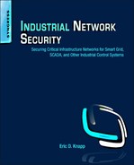
Control Loops
A control loop consists of the devices responsible for a particular automated process (see Chapter 5, “How Industrial Networks Operate”). Applying this list of devices to a functional group is relatively simple. In most instances, a control loop will consist of a PLC and any related inputs and outputs, as illustrated in Figure 7.1. If an IED is a direct input or output of the control logic, those devices share a functional group with the controller; if not, they do not.
Where defining a functional group based on network connectivity is a broad example that might result in a handful of functional groups, building a functional group based on a control loop is a very precise example. The functional groups created will be numerous, and each will contain a relatively small number of devices (a specific PLC or RTU and a collection of relays and IEDs).
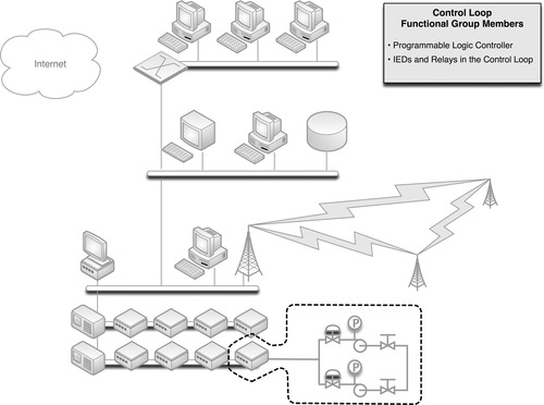
Supervisory Controls
Each control loop is also connected to some sort of supervisory control—typically an HMI—that is responsible for the configuration, monitoring, and management of the automated process. Because the HMI is responsible for the PLC, these two devices belong to a common functional group. However, because the HMI is not directly responsible for those IEDs connected to the PLC, these items are not necessarily in a common functional group as the HMI (they belong to a common functional group based on some other common criteria, such as protocol use). Figure 7.2 shows a common supervisory functional group.
All PLCs controlled by the HMI are included, as are any “master” HMI or control management systems that might have responsibility or control over the initial HMI (see Chapter 5, “How Industrial Networks Operate”). Other HMIs are not included, as they are not the responsibility of the initial HMI. Rather, each HMI would represent its own functional group. If a common master controller is in use to manage multiple HMIs, each HMI’s distinct functional group will contain the same master, creating an overlap between multiple functional groups.
Note
There are many other devices, such as I/O drives, printers, and safety systems that may also be connected to an HMI and therefore might also be included in the HMI’s functional group. However, these items are not shown in Figure 7.2 in order to simplify the illustration.
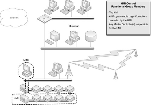
Control Processes
If a Master Controller or Master Terminal Unit (MTU) is used to manage multiple HMIs, each responsible for a specific part of a larger control process (see Chapter 5, “How Industrial Networks Operate”), that device represents the root of yet another functional group—this time containing all relevant HMIs, as shown in Figure 7.3.
This example also introduces the concept of process communication and historization. If an MTU interfaces with an ICCP server, for example, in order to communicate bulk electrical load to another electrical entity, the ICCP server should also be included in the MTU’s functional group. Similarly, if the process information from the MTU is fed into a Data Historian, that system should also be included.
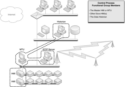
Control Data Storage
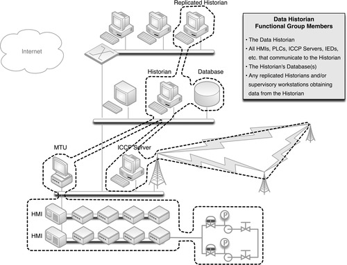
Many industrial automation and control system devices generate data, reflecting current configurations, the status of a process, alarms, and other information. This information is typically collected and “historized” by a Data Historian (see Chapter 5, “How Industrial Networks Operate”). The Data Historian system may connect to many—potentially all—devices throughout the control system network, supervisory network, and in some cases the business network, as illustrated in Figure 7.4.
Trading Communications
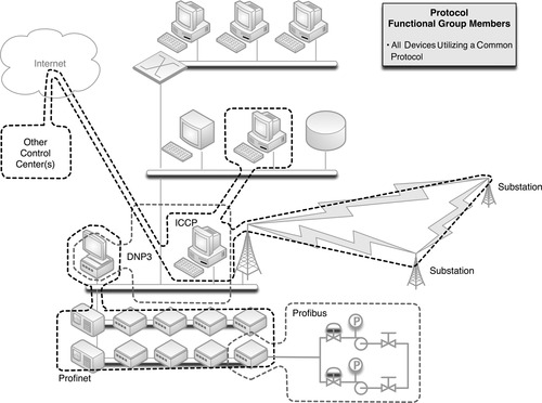
The need to communicate between control centers is sufficient enough to justify a specialized industrial protocol, developed specifically for that task: the Inter Control Center Communication Protocol, or ICCP (see Chapter 4, “Industrial Network Protocols”). ICCP connections require explicitly defined connections between clients and servers, and therefore, any operation utilizing ICCP to communicate with a field facility and/or a peer company will have one or more ICCP servers and one or more ICCP clients (these can be a single physical server or multiple distributed servers). This is the first example of a functional group that extends over Wide Area Networks, as illustrated in Figure 7.5.
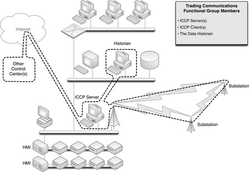
One thing to remember when assessing this functional group is that the remote client devices are all explicitly defined, even if owned by another company and hosted at its facility. These remote clients should be included within the functional group, as they have a direct relationship to any local ICCP servers that may be in use.
Because ICCP connections are typically used for trading, access to operational information is necessary. This could be a manual or automated informative process, which most likely involves the historized data stores of the Data Historian (or a subsystem thereof); as such, the Data Historian is included in this example of a “Trading Communications” enclave.
Remote Access
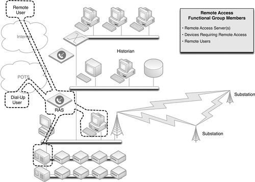
ICCP is but one, specialized method of remotely accessing a system. Many control systems and industrial devices—including HMIs, PLCs, RTUs, and even IEDs—allow remote access for technical support and diagnostics. This access could be via dial-up connection, or via a routable network connection. Remote access to control system devices, if it is provided, should be controlled via specialized virtual private networks (VPNs) or remote access servers (RAS), and should only allow explicitly defined, point-to-point connections from known entities, over secure and encrypted channels. These explicitly defined users, the devices that they access, and any VPN or RAS systems that are used constitute a remote access functional group, as illustrated in Figure 7.6.
Users and Roles
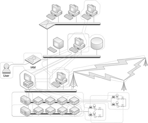
Every system is ultimately accessed by either a user or another system. Until now, functional groups have been built around the latter: explicitly defining which devices should legitimately be communicating with other devices. For human interaction, such as an operator accessing an HMI to adjust a process, it is just as important to define which users should legitimately be communicating with which devices. This requires a degree of Identity and Authentication Management (IAM), which defines users and their roles. The most well-known example of an IAM is Microsoft’s Active Directory services, although many other commercial IAM systems exist. Figure 7.7 illustrates the concept of a functional group containing a user and those devices that the user is allowed to interface.
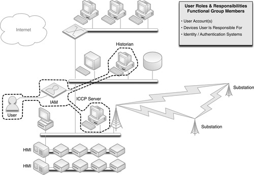
Mapping roles and responsibilities to devices can be tedious but is very important, as the resulting functional group can be used to monitor for unauthorized access to a system by an otherwise legitimate user. That is, an employee with control system access to a certain HMI, upon termination of his or her employment, might decide to tamper with other systems. By placing a user in a functional group with only those devices he or she should be using, this type of activity could be easily detected and possibly prevented (remember, defining functional groups is only the first step to building a secure enclave. The groups must be further refined into actual enclaves, and then secured internally and at the perimeter, as discussed under “Securing Enclave Perimeters” and “Securing Enclave Interiors”).
Protocols
The protocols that a device uses in industrial networks can be explicitly defined, and so it should be, in order to create functional groups based on protocols. Only devices that are known to use DNP3 should ever use DNP3, and if any other device uses DNP3, it is a notable exception that should be detected quickly and prevented outright if possible. The areas where a specific industrial protocol is commonly used has already been discussed in Chapter 4, “Industrial Network Protocols.” Now, the specific devices using specific industrial protocols should be identified and recorded, in order to build one more important functional group, as shown in Figure 7.8.
Criticality
Enclave-based security is about isolating common influencing factors into functional groups so that they can be kept separate and secure from other noninfluencing factors. The NRC dictates within CFR 73.54 that the criticality of assets be determined so that they can be separated into five logical security zones. 3 The NRC security zones are an example of enclave-based security, using a functional grouping based on criticality. NRC regulations also provide an example of how stronger security measures should be used as the criticality of the enclave increases, as the NRC regulatory Guide 5.71 clearly differentiates the level of security provided between zones.
3.U.S. Nuclear Regulatory Commission, 73.54 Protection of digital computer and communication systems and networks. < http://www.nrc.gov/reading-rm/doc-collections/cfr/part073/part073-0054.html>, March 27, 2009 (cited: January 19, 2011).
Critical assets, as defined by NERC, are those that can impact the operation of the bulk electric system. 4 They might include control centers, transmission substations, generation systems, disaster recovery systems, black start generators, load shedding systems and facilities, special protection systems, etc. 5 They can be identified using a simple methodology (see Chapter 2, “About Industrial Networks”). Determining the criticality of an enclave is a similarly straightforward process, and uses a similar methodology, as illustrated in Figure 7.9.
4.North American Reliability Corporation, Standard CIP-002-3. Cyber Security—Critical Cyber Asset Identification. < http://www.nerc.com/files/CIP-002-3.pdf>, December 16, 2009 (cited: January 19, 2011).
5.Ibid.
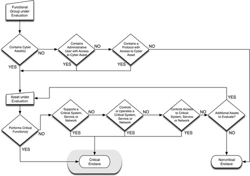
Critical assets are extrapolated to the critical function group(s) to which they belong, which may or may not contain other critical and/or noncritical assets. Any enclave that includes that function group (and therefore the critical asset) is a critical enclave.
Tip
While grading the importance of an asset for compliance can be construed as a means to measure accountability (and fines), it also allows us to improve threat detection and measure the severity of an event should one occur. By taking the time and making the effort to identify critical assets and enclaves, you can also greatly improve your threat detection capability, by configuring security monitoring tools to weight the perceived severity of suspicious activities, ranking them in order of consequence and priority. This is discussed in more detail in Chapter 9, “Monitoring Enclaves.”
However, simply defining functional groups around criticality to identify enclaves will result in very few enclaves (a total of five, using the NRC guidelines). In contrast, the more enclaves that are defined the stronger the security of the industrial network as a whole, and so a broader methodology—which identifies many more distinct enclaves—is preferred. Therefore, criticality should be assessed within the context of the previously defined functional groups. In this way the most critical systems will be protected by an additional layer of separation—within the inherent security of the enclave itself and then the additional protections between critical and noncritical items within that enclave. This will help to secure critical devices from the insider threat, such as a disgruntled employee who already has legitimate physical and logical access to the parent enclave. It also prevents lateral attack from one critical system to the next: if all critical systems are grouped together solely because they are all “critical,” a successful breach of one critical system puts the entire critical infrastructure at risk.
Using Functional Groups to Identify Enclaves
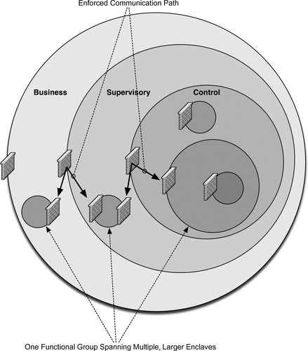
Defining groups based on services, protocols, criticality, and other factors is an excellent way to eliminate unknown, unauthorized devices from a group. Simply, if two devices do not share a common quality, there is no way for them to communicate. Unfortunately, many devices support multiple protocols, applications, services, and other qualities, resulting in multiple overlapping functional groups. Figure 7.10 shows two overlapping functional groups, based on a common controller, as well as two functional groups based on protocol, which then partially overlap with the first group.
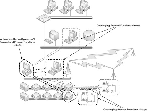
This illustrates the difficulties of defining clear-cut groups when so many variables are in play. Superimposing Figures 7.1 through 7.8 atop each other creates many overlapping functional groups, which are difficult to make sense of (as shown in Figure 7.11). Ideally, every functional group would contain a clear demarcation from every other group, and each demarcation would be secured using a unique protective device (see “Securing Enclave Perimeters”). However, in many cases it is necessary to simplify the functional groups using a common quality shared between groups, effectively combining overlapping functional groups into a single, larger enclave.
Ultimately, the process of distilling the many functional groups into manageable ones will result in several defined security enclaves, with a clear understanding of the boundaries of that enclave, and the users, devices, and protocols that are contained within.
Tip
Carefully document each functional group as well as the devices, services, protocols, and users within it. These lists will come in handy when establishing the enclaves (see “Establishing Enclaves”) as well as when implementing perimeter defenses (see “Securing Enclave Perimeters”) and monitoring enclave behavior (see Chapter 9, “Monitoring Enclaves”).
Establishing Enclaves
Once the process of pairing down the dozens of functional groups has been completed and the groups have been consolidated where necessary into larger overlapping groups, the enclaves can be established. Logically, the enclaves have already been defined at this point, with each consolidation of functional groups equating to a single security enclave.
The process of establishing enclaves can be summarized as follows:
1. Identifying the boundaries of each enclave so that perimeter defenses can be deployed in the correct location.
2. Making any necessary changes to the network so that the network architecture aligns with the defined enclaves.
3. Documenting the enclave for purposes of policy development and enforcement.
4. Documenting the enclave for purposes of security device configuration.
Note
Establishing an enclave is simply a means of mapping those functional groups that need to be isolated to the network architecture, policies, and configurations that are necessary to enforce that isolation. That is, the enclave itself is just a logical entity, which must then still be secured (see “Securing Enclave Perimeters” and “Securing Enclave Interiors”).
Identifying Enclave Perimeters
Once an enclave is identified, it must be mapped to the network so that clear electronic perimeters can be defined. While this process is required under NERC regulation CIP 0056, it is a necessary process that should be performed for any industrial network regardless of regulatory concerns, as an enclave can only be secured if there are defined and control entry points. In many cases the demarcation of the enclave will be very clear; for example, there may be a single network connection between a control center’s supervisory LAN and the control system network. In some instances, multiple connections might exist; for example, a power generation facility might connect to both supervisory and control networks, as well as directly to substations or remote field stations. All network connections into or out of an enclave comprise that enclave’s electronic perimeter.
6.North American Reliability Corporation, Standard CIP-005-3. Cyber Security—Electronic Security Perimeter(s). < http://www.nerc.com/files/CIP-005-3.pdf>, December 16, 2009 (cited: January 19, 2011).
Tip
Wireless, dial-up, and other remote connectivity are easy to overlook when identifying perimeters. If a wireless access point is located inside the enclave, a wireless user could connect directly to that enclave via a Wi-Fi connection. The access point, therefore, is part of the enclave’s perimeter, even if it is physically connected well inside the enclave. When securing the perimeter, the access point must also be secured (see “Securing Enclave Perimeters”). Consideration of all remote connection points in defining enclave perimeters will result in a more secure enclave, and will also comply with NERC CIP regulatory requirement CIP 005 R1.1 and R1.2, which dictate that access points to the ESP “shall include any externally connected communication end point (e.g., dial-up modems) terminating at any device within the Electronic Security Perimeter.”7
7.Ibid.
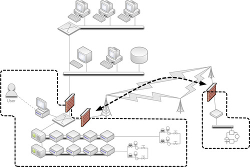
In some instances, such as the one illustrated in Figure 7.12, a single enclave may consist of multiple, geographically or otherwise separated groups. In these cases, the enclave is still considered to be a single enclave. If there are any network connections between the two (or more) locations, they should be held to the same controls as the rest of the enclaves. That is, there should be no communications across those links that do not originate and terminate within the enclave, and if outside communication is required (i.e., a communication that either originates or terminates outside of the enclave), it must occur through defined and secure access points. One common method of interconnecting distributed enclaves is the use of a dedicated VPN or other encrypted gateway, while for extremely critical enclaves, a dedicated network connection or fiber cable may be used so that physical separation is maintained.
The goal is that each enclave be isolated as strictly as possible, with as few connections as possible between that enclave and any other directly adjacent (or surrounding) enclave. Figure 7.13 shows how, by providing a single access point in and out of an enclave, that point can be secured using a perimeter security device such as a firewall or IPS. In the event of a single enclave that is split (geographically or by another enclave), inter-enclave communication can still be allowed: in this case through the use of perimeter firewalls, which effectively enforce a point-to-point route between the split enclaves (this path should also be encrypted).
In scenarios where an enclave needs to be extended across another enclave boundary, consider the functional goals of that extension. For example, in many cases a business user may require access to information originating from within a secure SCADA enclave. However, there is no requirement for the business user to communicate back into the SCADA environment. In situations like these, one-way communications can and should be enforced, either by provisioning intermediate perimeters (e.g., the firewalls shown in Figure 7.13) to disallow inbound traffic or through the use of a data diode or unidirectional gateway.
Network Alterations
No device that does not belong to a defined enclave should be directly connected to that enclave or to any device within that enclave.
In many cases, however, there will be devices identified that have access to or are connected to an enclave even though they do not belong to any of the functional groups within that enclave. For example, a printer or workstation that does not belong to the enclave might be connected to a local switch or router interface, or (as in the example under “Identifying Enclave Perimeters”) a wireless access point. The aberration may be the result of improper network design or improper network addressing—whatever the result, these exceptions need to be resolved before an enclave can be secured.
In other cases, it may not be possible to clearly identify the perimeter of an enclave. For example, if supervisory, control, and enterprise systems are all interconnected via a flat network (a network that is switched purely at layer 2, without network routing or other separation of devices) or a wireless network, it will not be possible to isolate any group from any other. In these cases, a complete network redesign may be necessary to separate the enclaves to the point where only devices that belong in an enclave are directly connected to it via the network.
Enclaves and Security Policy Development
Once enclaves are defined and the necessary adjustments to the network architecture are made, a distinct milestone is reached. With defined enclaves in place, the organization is armed with the information needed to satisfy several compliance requirements of NERC CIP, ISA-99, CFATS, and others.
Documenting all enclaves within the context of the organization’s security policy provides many benefits, by clearly identifying what systems may be accessed by what other systems, and how. This will facilitate policy documentation for compliance, security training and review materials, and similar security policy functions required by NERC CIP 003, 8 NERC CIP 005, 9 ISA-99 FR5, 10 CFATS Risk Based Performance Standards 8.2, 11 and NRC 10 CFR 73.54 and NRC RG 5.71 section C.3.2. 12
8.North American Reliability Corporation, Standard CIP-003-3. Cyber Security—Security Management Controls. < http://www.nerc.com/files/CIP-003-3.pdf>, December 16, 2009 (cited: January 19, 2011).
9.North American Reliability Corporation, Standard CIP-005-3. Cyber Security—Electronic Security Perimeter(s). < http://www.nerc.com/files/CIP-005-3.pdf>, December 16, 2009 (cited: January 19, 2011).
10.International Society of Automation, Standard ANSI/ISA-99.02.01-2009, Industrial Automation and Control System Security.
11.Department of Homeland Security, Risk-Based Performance Standards Guidance, Chemical Facility Anti-Terrorism Standards, May, 2009.
12.U.S. Nuclear Regulatory Commission, Regulatory Guide 5.71 (New Regulatory Guide), Cyber Security Programs for Nuclear Facilities, January, 2010.
Documentation of enclaves also defines how ongoing security assessments and vulnerability testing should be measured. This is again useful for compliance, including NERC CIP 008, 13 ISA-99, 14 CFATS Risk Based Performance Standards 8.5, 15 and NRC CFR 73.54 and NRC RG 5.71 section C.13. 16
13.North American Reliability Corporation, Standard CIP-008-3. Cyber Security—Incident Reporting and Response Planning. < http://www.nerc.com/files/CIP-008-3.pdf>, December 16, 2009 (cited: January 19, 2011).
14.International Society of Automation, Standard ANSI/ISA-99.02.01-2009, Industrial Automation and Control System Security.
15.Department of Homeland Security, Risk-Based Performance Standards Guidance, Chemical Facility Anti-Terrorism Standards, May, 2009.
16.U.S. Nuclear Regulatory Commission, Regulatory Guide 5.71 (New Regulatory Guide), Cyber Security Programs for Nuclear Facilities, January, 2010.
Enclaves and Security Device Configurations
Documentation can be a function of security as well as compliance. Firewalls, IDS and IPS systems, Security Information and Event Management (SIEM) systems, and many other security systems support the use of variables, which are used to map hard security configurations to organizational security policies.
For each enclave, the following lists should be maintained at a minimum:
• Devices belonging to the enclave, by IP address
• Users with authority over the enclave, by username or other identifier
• Protocols, Ports, and Services in use within the enclave
If additional metrics are identifiable, additional lists should be created. Depending on the number of enclaves that have been defined, this may require several lists—three (device, users, and ports/services) for every established enclave. Additional lists could also be maintained, for example, users by shift, in addition to users defined solely by enclave. However, unless there is a centralized authentication system in use, maintaining these lists may be cumbersome.
When finished, these variables will appear as follows:
$ControlSystem_Enclave01_Devices
192.168.1.0/24
10.2.2.0/29
$ControlSystem_Enclave01_Users
jcarson
jrhewing
kdfrog
mlisa
$ControlSystem_Enclave01_PortsServices
TCP 502 #Modbus TCP
TCP 20000 #DNP3
The creation of these variables will assist in the creation of firewall and IDS rules for the enforcement of the enclave’s perimeter, as discussed under “Securing Enclave Perimeters,” and will also allow for security monitoring tools to detect policy exceptions and generate alarms, as discussed in Chapter 9, “Monitoring Enclaves.”
Note
In this book, variables are defined using var VariableName [value1, value2, value3, etc.] and referenced using $VariableName, in line with standard Snort syntax. However, depending on the device used, the specific syntax for defining and referencing variables may differ. For example, while a variable is defined as follows using Snort
var ControlSystem_Enclave01_Devices 192.168.1.0/24
the same example for an iptables firewall is defined within the iptables configuration file as follows:
ControlSystem_Enclave01_Devices 192.168.1.0/24
To define a usable variable that maps to an enclave, var ControlSystem_Enclave01_Devices [192.168.1.0/24, 10.2.2.0/29] is used, and then that variable is referenced within a specific rule using $ControlSystem_Enclave01_Devices. This is a logical extension of the classic $HOME_NET variable used in many IDS policies, only applied to a specific enclave. This allows for exception-based detection of unauthorized behavior within the enclave, as seen in the following rule to detect any traffic with a destination IP of a device within the defined control system enclave:
alert tcp any any -> $ControlSystem_Enclave01_Devices
With enclaves defined, and relevant variables defined for each, the enclaves can now be secured using perimeter and host security devices.
Securing Enclave Perimeters
Establishing an Electronic Security Perimeter (ESP) around a defined enclave provides direct protection against unauthorized access to the enclosed systems and also prevents the enclosed systems from accessing external systems from the inside out. To establish an ESP and effectively secure inbound and outbound traffic, two things must occur:
1. All inbound and outbound traffic must be forced through one or more known network connections that can be monitored and controlled.
2. One or more security devices must be placed in-line at each of these connections.
For each enclave, appropriate security devices should be selected and implemented using the recommendations below.
Selecting Perimeter Security Devices
At a minimum, a firewall is typically required. Additional security—provided by IDS, IPS, and a variety of specialized and hybrid devices such as Unified Threat Management (UTM) devices, Network Whitelisting devices, Application Monitors, Industrial Protocol Filters, etc.—may be desired as well. Typically, the criticality of the enclave (see “Criticality”) dictates the degree of security that is required. Table 7.1 maps the criticality of an enclave to required security measures of NERC CIP and NRC CFR 73.54, as well as recommended enhancements to improve security beyond regulatory requirements.
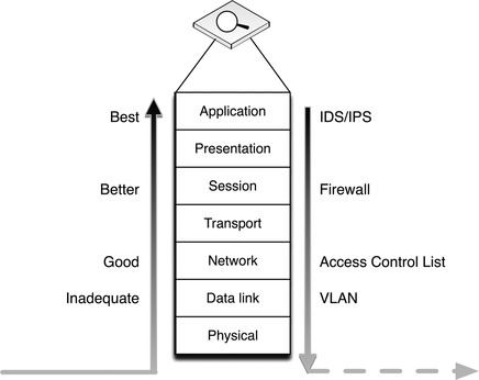
Table 7.1 recommends that both a firewall and an IPS be used at each security perimeter. This is because firewalls and IPS devices serve different functions: firewalls enforcing what types of traffic are allowed to pass through the perimeter; and Intrusion Prevention Systems closely examining the traffic that is allowed through in order to detect “legitimate” traffic with malicious intent—that is, exploit code, malware, etc—that is transferred over allowed paths. Using both devices together provides two mutual benefits: first, it allows the IPS to perform deep packet inspection (DPI) on all traffic allowed in through the firewall; second, the firewall limits the allowed traffic based on the defined parameters of the security enclave, freeing the IPS to focus its resources on just that traffic and therefore enabling it to enforce a more comprehensive and robust set of IPS rules.
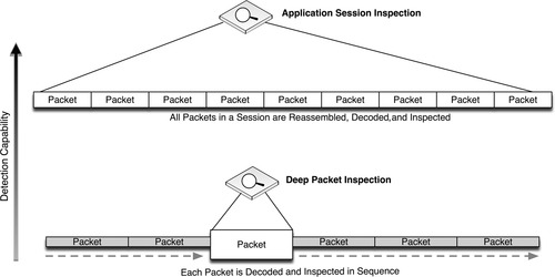
For even greater protection, DPI can be used to analyze specific industrial protocol functions. This may require the use of specialized SCADA IDS or SCADA firewall devices that are designed to identify these protocol functions, or even the use of an ICS protocol filter or application monitoring tool that provides DPI across all packets within a session—providing detection and analysis capability to protocol and application contents that span multiple packets. This provides an even deeper look into the contents of network traffic. Figure 7.14 illustrates the increased security capability of firewalls, IDS/IPS devices, and application session monitoring systems.
In the most critical areas, application layer session monitoring provides a valuable and necessary level of assurance, as they are able to detect both low-level protocol anomalies (such as a base64-encoded application stream inside of HTTP, used by many APTs and botnets) and application policy violations (such as an unauthorized attempt to write a new configuration to a PLC). However, unless monitoring very simple application protocols, where the desired contents are distinctly packaged within a single packet or frame, the application session must be reassembled prior to monitoring as illustrated in Figure 7.15.
The most stringent perimeter security device may be the data diode, also referred to as a unidirectional gateway. A data diode is, very simply, a one-way network connection—often a physically restricted connection that uses only one fiber-optic strand from a transmit/receive pair. By only using TX optics, it is physically impossible for any digital communications to occur in a highly sensitive network area containing control system devices, while supervisory data may be allowed to communicate out of that highly secure enclave into the SCADA DMZ or beyond. In certain instances, such as for the storage of highly sensitive documents, the diode may be reversed, such that information can be sent into a secure enclave that is then physically prevented from communicating that information back outside of the enclave.
Implementing Perimeter Security Devices
Once appropriate security product(s) have been identified, they must be installed and configured appropriately. Luckily, the process of identifying, establishing, and documenting enclaves will simplify this process. The following guidelines will help to configure firewalls, IDS/IPS devices, and application monitors using the variables defined earlier under “Establishing Enclaves.”
Firewall Configuration Guidelines
Firewalls control communication using a defined configuration policy, typically consisting of Accept (allow) and Drop (deny) statements. Most firewalls will enforce a configuration in sequence, such that starting with a broadly defined policy, such as Deny All, which will drop all inbound traffic by default. These broad rules can then be overruled by subsequent, more focused rules. Therefore, the following firewall policy would only allow a single IP address to communicate outside of the firewall on port 80 (HTTP).
Deny All
Allow 10.0.0.2 to Any Port 80
Note
Firewall rule examples are written generically so that they can be more easily understood. Depending on the firewall used, specific rule syntax may have to be used, while some firewalls are configured exclusively via a graphical user interface.
Determining what rules should be configured is typically easier in an industrial network because the nature of an industrial network is such that there is no need to accommodate the full diversity of applications and services typically found in an enterprise network. This is especially true when configuring a specific firewall against a specific enclave: the enclave will by its nature be limited in scope, resulting in concise firewall policies. The method of properly configuring an enclave firewall is as follows:
1. Begin with bidirectional Deny All rules.
2. Configure specific exceptions, using the defined variables $ControlSystem_Enclave01_Devices and $ControlSystem_Enclave01_PortsServices.
3. Verify that all Allow rules are explicitly defined (i.e., no All rules).
One simple way to configure a firewall is to follow the guidelines of the National Infrastructure Security Coordination Center (NISCC) “Good Practice Guide on Firewall Deployment for SCADA and Process Control Networks,” using the defined enclave variables as detailed in Table 7.2. 17
17.National Infrastructure Security Coordination Center, NISCC Good Practice Guide on Firewall Deployment for SCADA and Process Control Networks, British Columbia Institute of Technology (BCIT), February 15, 2005.
| aNational Infrastructure Security Coordination Center, NISCC Good Practice Guide on Firewall Deployment for SCADA and Process Control Networks. British Columbia Institute of Technology (BCIT). February 15, 2005. | ||
| NISCC Recommendations | Example Rule Using Enclave Variables | Notes |
|---|---|---|
| Start with universal exclusion as a default policy | Deny All / Permit None | Firewalls should explicitly deny all traffic inbound and outbound as the default policy. |
| Ports and services between the control system environment and an external network should be enabled and permissions granted on a specific case by case basis | Allow 10.2.2.120 port 162 to 192.168.1.15 port 162 | Comments used within the firewall configuration file can be used to document special cases, permissions, and other details. |
| #Allow SNMP traps from router ip 10.2.2.120 to network management station ip 192.168.1.15, authorized by John Doe on April 1 2005 | ||
| All “permit” rules should be both IP address and TCP/UDP port specific, and stateful if appropriate, and shall restrict traffic to specific IP address or range of addresses | N/A | This guideline can be enforced by using $ControlSystem_Enclave01_Devices and $ControlSystem_Enclave01_PortsServices to define rules. |
| All traffic on the SCADA and DCS network(s) are typically based only on routable IP protocols, either TCP/IP or UDP/IP; thus, any non-IP protocol should be dropped | N/A | By using $ControlSystem_Enclave01_PortsServices within all defined rules, only protocols explicitly allowed within that enclave will be accepted by the firewall, and all others will be dropped by the overarching Deny All rule. |
| Prevent traffic from transiting directly from the Process Control / SCADA network to the enterprise network; all traffic should terminate in the DMZ | Deny [Not $Neighboring Enclave1, Not $Neighboring Enclave2] to $ControlSystem_Enclave01_Devices | By configuring a rule on each enclave that explicitly denies all traffic to and from any enclave that is NOT a neighboring enclave will prevent any transitive traffic. All traffic will need to be terminated and reestablished using a device local to that enclave. |
| Deny $ControlSystem_Enclave01_Devices to [Not $Neighboring Enclave1, Not $Neighboring Enclave2] | ||
| Any protocol allowed between the DCS and the SCADA DMZ is explicitly NOT allowed between SCADA DMZ and enterprise networks (and vice versa) | At the demarcation between the enterprise network and SCADA DMZ: | These rules enforce the concept of “disjointing” protocols, and further prevents transitive communication from occurring across an enclave. |
| Deny $ControlSystem_Enclave01_PortsServices to $EnterpriseNetwork_Enclave01_Devices | ||
| At the demarcation between the DCS and SCADA DMZ: | ||
| Deny $EnterpriseNetwork_Enclave01_ PortsServices to $ControlSystem_Enclave01_ Devices | ||
| Allow outbound packets from the PCN or DMZ only if those packets have a correct source IP address assigned to the PCN or DMZ devices | N/A | Explicitly defined Deny All rules combined with explicitly defined known-good IP addresses using $ControlSystem_Enclave01_Devices ensures that all outbound packets are from a correct source IP. |
| Firewalls may also be able to detect spoofed IP addresses. In addition, network activity monitoring using a Network Behavior Anomaly Detection (NBAD), Security Information and Event Management (SIEM), or Log Management solution may be able to detect instances of a known-good IP address originating from an unexpected device based on MAC Address or some other identifying factor (see Chapter 9, “Monitoring Enclaves”) | ||
| Control network devices should not be allowed to access the Internet | At the Internet firewall: | Because all devices in all enclaves have been identified and mapped into variables, these devices can be explicitly denied at the Internet firewall. |
| Deny [$ControlSystem_Enclave01_ Devices, $ControlSystem_Enclave02_ Devices, $ControlSystem_Enclave03_ Devices, $ControlSystem_Enclave04_ Devices] | ||
| Control system networks shall not be directly connected to the Internet, even if protected via a firewall | N/A | Using the enclave approach, no control system should be directly connected to the Internet (see “Establishing Enclaves”). |
| All firewall management traffic be: 1. Either via a separate, secured management network (e.g., out of band) or over an encrypted network with two-factor authentication 2. Restricted by IP address to specific management stations | N/A | This recommendation supports the establishment of a Firewall Management enclave using the methods described earlier under “Establishing Enclaves.” By placing all firewall management interfaces and management stations in an enclave, which is isolated from the rest of the network, the traffic can be kept separate and secured. |
Intrusion Detection and Prevention (IDS/IPS) Configuration Guidelines
IDS and IPS devices inspect network packets for signs of malicious code or exploits. Intrusion Detection refers to passive inspection. An IDS examines packets and compares them against a set of detection signatures, and issues an alert when there is a match. Intrusion Prevention refers to active inspection, where traffic is matched against IDS rules, but where specific actions can be taken in addition to alerting. IDS actions can include Alert (generate a custom message and log the packet), Log (log the packet), and Pass (ignore the packet), while IPS actions can also include Drop (drop the packet and log it), Reject (drop the packet and initiate a TCP reset to kill the session), and sDrop (drop the packet, but do not log it). In addition, both IDS and IPS rules can use the Activate and Dynamic actions, the former of which activates another rule, and the latter of which remains idle until activated by an Activate rule. 18
18.Snort.org, SNORT Users Manual 2.9.0. < http://www.snort.org/assets/156/snort_manual.pdf>, December 2, 2010 (cited: January 19, 2011).
Both IDS and IPS devices can be deployed either out-of-line using a network span or tap port or in-line using two network interfaces, although an IPS can only actively block traffic if it is deployed in-line.
An enabled collection of IDS/IPS detection signatures is referred to as an IDS/IPS policy, and this policy will dictate what types of threats may be detected by the device, as well as the degree and scope of events that will be generated. While active blocking of malicious traffic is important, the IDS/IPS events that are generated can also be analyzed to provide other important indicators—including network behavior, larger threat incidents, etc. (see Chapter 9, “Monitoring Enclaves”). Signatures generally follow a format similar to a firewall rule, where there is an identified source and destination address and/or port, as well as an action. In addition, IDS/IPS signatures may match against specific contents of a packet, looking for patterns within the packet that indicate a known exploit (i.e., a “signature”). Common IDS/IPS signature syntax follows the de facto standards defined by Snort, an open-source IDS project owned by SourceFire. An example signature is written as follows:
[Action] [Protocol] [Source Address] [Source Port] [Direction Indicator] [Destination Address] [Destination Port] [Rule Options]
which when written in correct syntax looks like
drop tcp 10.2.2.1 80 -> 192.168.1.1 80 (flags: <optional snort flags>; msg: “<message text>”; content: <this is what the rule is looking for>; reference: <reference to external threat source>;)
To highlight the difference between a firewall rule and an IDS/IPS signature, consider the following example:
drop tcp 10.2.2.1 80 -> any any
Without any rule options, the previous rule is essentially the same as the firewall rule Deny 10.2.2.1port 80, which would block all traffic originating from 10.2.2.1 on port 80, effectively preventing that user from accessing the web (via HTTP port 80). However, the ability to match packet contents within the rule options enables an IDS/IPS device to control traffic at a much more granular level, such as
drop tcp 10.2.2.1 80 -> any any (msg: “drop http POST”; content: “POST”;)
This rule functions differently, only dropping traffic from the source address in question if the HTTP traffic contains a POST request (used by many web forms or applications attempting to upload a file to a web server over HTTP).
Note
IDS/IPS rule examples are written using Snort syntax, as it is the de facto signature creation language. However, many IDS or IPS devices support proprietary rule syntax, GUI rule editors, or other rule creation methods. Depending on the product used, the example rules in this book may or may not function as intended. All rules should always be tested prior to deployment.
As with a firewall configurations, determining the exact IDS/IPS policy to be enforced is the first step in correctly configuring the device. Also as with firewalls, the enclave variables defined earlier under “Establishing Enclaves” are valuable tools that can be used to write succinct and highly relevant signatures. However, unlike a firewall which starts with a simple Deny All rule, an IDS/IPS should be deployed “large”—with many active signatures—and then pruned back to the specific requirements of the enclave. A method of properly configuring an IDS/IPS is as follows:
1. Begin with a more robust signature set, with many active rules.
2. If a protocol or service is not allowed in the enclave, replace any specific detection signatures associated with that protocol or service with a broader rule that will block all traffic from that protocol or service (i.e., drop unauthorized ports and services).
3. If a protocol or service is allowed in the enclave, keep all detection signatures associated with that protocol or service active.
3a. For all active signatures, assess the appropriate action, using Table 7.3.
4. Keep all IDS signatures current and up to date.
Remember that an IDS or IPS can be used in a purely passive mode, to analyze traffic that is allowed, including traffic within an enclave (that is, between two devices within the same enclave, that do not cross an enclave perimeter). Passive monitoring will generate alerts and logs that can be useful in many security operations, including forensic investigations, threat detection, and compliance reporting (see Chapter 9, “Monitoring Enclaves,” and Chapter 10, “Standards and Regulations”).
IDS/IPS rules should be tailored to the appropriate enclave using the variables defined in “Establishing Enclaves.” A typical Snort variable is established using the var command, as follows:
var VARIABLE_NAME <alphanumeric value>.
The var command can be used ubiquitously, or specialized ipvar and portvar can be used exclusively for IP addresses and ports, respectively. 19 In the enclave method described earlier under “Establishing Enclaves,” variables would be defined as
19.Ibid.
ipvar ControlSystem_Enclave01_Devices [192.168.1.0/24, 10.2.2.0/29]
var ControlSystem_Enclave01_Users [jcarson, jrhewing, kdfrog, mlisa]
portvar ControlSystem_Enclave01_PortsServices [502, 20000]
These variables can then be used extensively throughout the active detection signatures. For example, a signature designed to detect a known SCADA buffer overflow attack that is available within the Metasploit framework might appear as follows. (The following rule has been deliberately obfuscated; the complete rule can be obtained from Digital Bond at www.digitalbond.com.)
alert tcp !$ControlSystem_Enclave01_Devices -> $ControlSystem_Enclave01_Devices 20222 (msg: “SCADA ODBC Overflow Attempt”; content: <long string in the second application packet in a TCP session>; reference:cve,2008-2639; reference:url, http://www.digitalbond.com/index.php/research/ids-signatures/m1111601/; sid:1111601; rev:2; priority:1;)
Note
Many Snort rules reference the $HOME_NET or $MY_NET variable. The use of multiple $ControlSystem_Enclave01_Devices variables (one for each defined enclave) accomplishes the same purpose, effectively defining a unique $HOME_NET for each enclave. The nomenclature of $ControlSystem_Enclave01_Devices is deliberately verbose in order to easily identify the variable’s contents, so that the examples within this book are easier to understand.
Additional examples include signatures designed to specifically block known infection vectors used by Stuxnet. 20 The first example looks for one of the early delivery mechanisms for the Stuxnet malware: specifically, a shortcut image file delivered via a WebDav connection. The second example detects Semens WinCC connection attempts, used in early Stuxnet infection phases.
20.NitroSecurity, Inc., Network Threat and Analysis Center, Nitrosecurity.com, January, 2011.
tcp !$ControlSystem_Enclave01_Devices $HTTP_PORTS -> $ControlSystem_Enclave01_Devices any (msg: “Possible Stuxnet Delivery: Microsoft WebDav PIF File Move Detected”; flow:from_server; content: “MOVE”; offset:0; within:5; content: “.pif”; distance:0; classtype:attempted-user; reference:cve, 2010-2568; reference:osvdb,66387; reference:bugtraq,41732; reference:secunia,40647; reference:research,20100720-01; sid:710072205; rev:1;)
tcp any any -> any 1433 (msg: “Possible Stuxnet Infection: Siemens Possible Rootkit.TmpHider connection attempt”; flow:to_server; content: “Server=|2e 5c|WinCC|3b|uid=WinCCConnect|3b|pwd=2WSXcder”; classtype:suspicious-login; reference:cve,2010-2772; reference:osvdb,66441; reference:bugtraq,41753; sid:710072201; rev:2;)
Recommended IDS/IPS Rules
Basic recommendations for IDS/IPS configuration include active block rules to
1. Prevent any undefined traffic from crossing enclave boundaries (where the disruption of the communication will not impact the reliability of a legitimate service).
2. Prevent any defined traffic containing malware or exploitation code from crossing enclave boundaries.
3. Detect and log suspicious or abnormal activity within an enclave (see “Securing Enclave Interiors” and Chapter 9, “Monitoring Enclaves”).
4. Log normal or legitimate activity within an enclave, which may be useful for compliance reporting (see Chapter 10, “Standards and Regulations”).
Caution
A false positive (a rule that triggers in response to unintended traffic, typically due to imprecisions in the detection signature) can block legitimate traffic and in a control system legitimate traffic could represent a necessary operational control. Only use block IPS rules where absolutely necessary, and only after extensive testing.
The greater the extent of functional isolation and separation into defined enclaves, the more concise and effective the IDS/IPS policy will be. Some basic IDS and IPS rules suitable for use in enclave perimeters include the following:
• Block any industrial network protocol packets that are the wrong size or length.
• Block any network traffic that is detected inbound to or outbound from any enclave where that is not expected or allowed.
• Block any industrial network protocol packets that are detected in any enclave where that protocol is not expected or allowed.
• Alert any authentication attempts, in order to log both successful and failed logins.
• Alert any industrial network port scans.
• Alert any industrial network protocol function codes of interest, such as:
• “Write” functions, including codes that write files or that clear, erase, or reset diagnostic counters.
• “System” functions, including codes that stop or restart a device.
• “System” functions that disable alerting or alarming.
• “Read” functions that request sensitive information.
• “Alarm” or “Exception” codes and messages.
While SCADA IDS/IPS devices may be able to detect and trigger upon industrial network protocol function codes and commands, specialized application monitoring devices may be more capable of analyzing the contents of application layer protocols.
Caution
IDS and IPS signatures are only able to block known threats, meaning that the IDS/IPS policy must be kept current in order to detect more recently identified attacks (virus, exploits, etc). Therefore, IDS/IPS products must be included within the overall Patch Management Strategy in order for the devices to remain effective (see Chapter 6, “Vulnerability and Risk Assessment”).
Anomaly based Intrusion Detection
So far, only signature-based detection has been discussed. However, many IDS and IPS systems also support detection based on anomaly detection. Anomaly detection uses statistical models to detect when something unusual is happening, on the premise that unexpected behavior could be the result of an attack.
The exact capabilities will vary from product to product, as there is no standard anomaly detection mechanism. Theoretically, anything monitored by the IDS could be used for anomaly detection. Because network flows are highly quantifiable, anomaly detection is often used to identify abnormal behavior in what devices are communicating, and how. Referred to as Network Anomaly Detection, these systems are able to detect a sudden increase in outbound traffic, an increase in sessions, an increase in total bytes transmitted, an increase in the number of unique destination IP addresses, or other quantifiable metrics.
Anomaly detection is useful because it does not require an explicitly defined signature in order to detect a threat. This allows anomaly detection systems to identify zero day attacks or other threats for which no detection signature exists. At the same time, however, anomaly detection trends toward a higher number of false positives, as a benign change in behavior can lead to an alert. It is for this reason that anomaly-based threat detection is typically used passively, generating alerts rather than actively blocking suspect traffic.
In industrial networks—especially in well-isolated control system enclaves—network behavior tends to be highly predictable, making anomaly detection more reliable.
Anomaly detection systems may be referred to as “rule-less” detection systems. This is because they do not pattern match against a defined signature, although they do use rules. However, unlike a normal IDS rule, anomaly rules are often based on thresholds and/or statistical deviations, such as in the following example:
An example of a threshold rule would use a hard upper- or lower-limit, most likely derived automatically by the anomaly detection system:
TotalDestinationIPs>34
As a general guideline, the greater the variation of the network traffic being monitored, the greater the chances of anomaly detection rules to generate a false positive.
Anomaly detection can be used across devices as well, using an information consolidation tool such as a Security Information and Event Management (SIEM) system. This system-level anomaly detection is discussed in more detail in Chapter 8, “Exception, Anomaly, and Threat Detection.”
Application and Protocol Monitoring in Industrial Networks
Because many industrial operations are controlled using specialized industrial network protocols that issue commands, read and write data, etc. using defined function codes, specialized devices can leverage that understanding along with Firewall, IDS, and IPS technology to enforce communications based on the specific operations being performed across the network.
In addition to the inspection of industrial protocol contents (e.g., DNP3 function codes), the applications themselves—the software that controls how those protocols are used—can also be inspected. This degree of Application Monitoring, also referred to as Session Inspection, allows the contents of an application (e.g., HMI, Web Browser) to be inspected even though it might exist across a large number of individual packets. That is, inspection can occur up to and include the contents of a file being transferred to a PLC, a virus definition downloaded from a web browser of update server, etc. Application Monitors provide a very broad and very deep look into how network traffic is being used, and are therefore especially useful in environments where both control systems and enterprise protocols and applications are in use.
Many specialized security devices are available for SCADA and control system environments that use either application or protocol monitoring to this degree. At the time of this writing, these devices include the Tofino Industrial Security Appliance and the Secure Crossing Zen Firewall, as well as other broader-use enterprise Application Data Monitors. The two former devices were designed specifically to identify the operations being performed within industrial protocols, to prevent unauthorized operations. The latter refers to a more general-purpose enterprise security appliance, which is able to support the most common industrial network protocols. Each of these specialized devices has specific strengths and weaknesses, which are summarized in Table 7.4.
Because these devices are highly specialized, configurations can vary widely. In general terms, a firewall capable of SCADA protocol inspection may utilize a rule as follows to block any protocol function from writing a configuration or register, or executing a system command (such as a device restart):
An IDS capable of SCADA protocol inspection may utilize a rule as follows, which looks for a specific function code within a DNP3 packet:
tcp any any -> $ControlSystem_Enclave01_Devices 502 (msg: “DNP function code 15, unsolicited alarms disabled”; content:“|15|”; offset:12; rev:1;)
In contrast, an application monitor performing full session decode may use syntax similar to the following rule to detect windows .LNK files within application traffic, which could indicate a possible Stuxnet delivery attempt.
FILTER_ID=189
NORM_ID=830472192
ALERT_ACTION=log-with-metadata
ALERT_LEVEL=13
ALERT_SEVERITY=10
DESCRIPTION=A Microsoft Windows .LNK file was detected
EXPRESSION=(objtype==application/vnd.ms-lnk)
Data Diodes and Unidirectional Gateways
Data diodes and unidirectional gateways work by physically preventing return communications over a fiber-optic connection, typically through the physical removal of the RX optics. This provides absolute physical layer security at the sake of bidirectional communications. Because the connection in one direction does not exist, data diodes are true air gaps, albeit in only one direction.
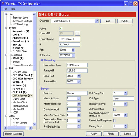
Because many network applications and protocols require bidirectional communication (such as TCP/IP, which requires a variety of handshakes and acknowledgments to establish and complete a session), considerations should be taken when using data diodes in order to ensure that the remaining one-way data path is capable of transferring the required traffic. To accommodate this concern, many data diode vendors implement a software-based solution, where the physical diode exists between two servers. These servers support a variety of bidirectional applications, so that the bidirectional requirements can be met fully at the transmitting end, and so that the receiving end can then spoof the behavior of the original transmitter—essentially tricking the application to operate over a one-way link. This allows an additional level of control over the applications and services that can be transmitted over the diode or gateway. An example of enabling DNP3 services over a unidirectional gateway is shown in Figure 7.16. While data diodes are physical layer devices that do not require any specific configuration, the communication servers may need to be correctly configured before these applications work correctly over the diode.
Securing Enclave Interiors
Unlike enclave perimeters, which by their definition have a clear point of demarcation that can be monitored and controlled, enclave interiors consist of specific devices as well as a variety of network communications between those devices. Securing an enclave’s interior is primarily accomplished through host-based security, which controls end-user authentication to a device, how that device communicates on the network, what files are accessed by that device, and what applications may be executed by it. Although monitoring the communications between hosts within an enclave is also useful for detecting threats, this is discussed in Chapter 9, “Monitoring Enclaves,” and will not be discussed in this chapter.
This chapter discusses three distinct areas of host security, including:
• Access Control, including user authentication and service availability
• Host-Based Network Security, including host firewalls and host intrusion detection systems (HIDS)
• Anti-Malware systems such as Anti-Virus (AV) and application whitelists (AWL)
Selecting Interior Security Systems
As a matter of best practices, all host access controls and host network security solutions should be implemented on all networked devices. However, not all network devices are capable of running additional security software, and in some cases the software may incur latency or unacceptable processor overhead. Table 7.5 shows which devices are typically capable of running the common methods of host security.
Where possible, one option of each type—access control, network security, and Anti-Malware—should be used. Especially where host security options are not possible, an external security control should be implemented.
Caution
Major control system asset vendors often recommend and/or support the use of particular host security options and may even perform regression testing to validate authorized tools. 21 This is an important consideration, especially when utilizing time-sensitive applications that could be affected by delay. In addition, many control system assets may use proprietary extensions or modifications of commercial operating systems that may conflict with some host security solutions. 22 Therefore, asset vendors should always be consulted prior to the installation of a commercial host security product.
21.K. Stouffer, J. Falco, K. Scarfone, National Institute of Standards and Technology, Special Publication 800-82 (Final Public Draft), Guide to Industrial Control Systems (ICS) Security, Section 6.3.1 Identification and Authentication, September, 2008.
22.Ibid.
Host Firewalls
A host firewall works just like a network firewall, and acts as an initial filter between the host and any attached network(s). The host firewall will allow or deny inbound traffic based on the firewall’s specific configuration. Typically, host firewalls are session-aware firewalls that allow control over distinct inbound and outbound application sessions.
Host IDS
Host IDS (HIDS) systems work like Network IDS, only they reside on a specific asset and monitor systems internal to that asset. Typically, HIDS devices may monitor system settings and configuration files, applications, and/or sensitive files. 23 These devices are differentiated from Anti-Virus and other host security options in that they can perform network packet inspection, and can therefore be used to directly mimic the behavior of a Network IDS by monitoring the host systems network interface(s) to detect or prevent inbound threats. HIDS can therefore be configured using the guidelines presented under “Intrusion Detection and Prevention (IDS/IPS) Configuration Guidelines.” Because an HIDS may also be able to inspect local files, the term is sometimes used for other host-based security devices such as Anti-Virus systems, or propriety host security implementations that provide overlapping security functions.
23.Ibid.
As with Network IDS, an HIDS device will generate alerts detailing any violations of the established policy. If the system is able to actively block the violation, it may be referred to as a Host IPS (HIPS).
Caution
Like Network based IDS/IPS systems, HIDS products require regular signature updates in order to detect more recently identified threats. HIDS should therefore be included in the overall Patch Management Strategy (see Chapter 6, “Vulnerability and Risk Assessment”).
Anti-Virus
Anti-Virus systems are designed to inspect files for malware. They work similarly to an IDS (and IDS systems can be used to detect malware), using signature-based detection to validate system files. When a signature matches known indications of a virus, Trojan, or other malware, the suspect file is typically quarantined so that it can be cleaned or deleted.
Caution
Like other signature-based detection systems, Anti-Virus systems require regular signature updates. Anti-Virus systems should therefore be included in the overall Patch Management Strategy (see Chapter 6, “Vulnerability and Risk Assessment”).
Application Whitelisting
Application whitelisting (AWL) offers a different approach to host security than traditional HIDS, Anti-Virus, and other “blacklist” technologies. A “blacklist” solution compares the monitored object to a list of what is known to be bad. This presents two issues: the first is that the blacklist must be continuously updated as new threats are discovered; the second is that there is no way to detect or block certain attacks, such as zero-days, and/or known attacks for which there is no available signatures. In contrast, a “whitelist” solution creates a list of what is known to be good and applies very simple logic: if it is not on the list, block it.
AWL solutions apply this logic to the applications on a host. In this way, even if a virus or Trojan does penetrate the control system’s perimeter defenses and finds its way onto a target system, the host itself will stop that malware from executing—rendering it inoperable.
AWL is well suited for use in control systems, where an asset should have explicitly defined ports and services. In addition, there is no need to continuously download, test, evaluate, and install signature updates. Rather, the AWL only needs to be updated and tested when the applications used on the host system are updated.
However, because AWL operates at the lowest levels of an operating environment, it introduces new code into the execution paths of all applications and services on that host. This adds latency to all functions of the host, which may cause unacceptable delay for time-sensitive operations, and requires full regression testing.
External Controls
When it is simply not possible to use host-based security tools, external tools may be required. For example, certain IDS, Firewalls, and other network security devices that are specialized for control system operations may be used to monitor and protect these assets. Many of these devices support serial as well as Ethernet interfaces, and can be deployed directly in front of a specific device or group of devices, including deployment within a specific process or loop.
Other external controls, such as Security Information and Event Management systems, may monitor a control system more holistically, using information available from other assets (such as an MTU or HMI), from other information stores (such as a Data Historian), or from the network itself. This information can be used to detect risk and threat activity across a variety of systems. This will be discussed more in Chapter 9, “Monitoring Enclaves.”
External controls, especially passive monitoring and logging, can also be used to supplement those assets that are already secured via a host firewall, host-based IDS, Anti-Virus, AWL, etc.
Summary
Through the identification and isolation of functional groups, quantifiable security enclaves can be defined. These enclaves can and should be secured at both the enclave perimeter and within the enclave interior, using a variety of tools including both network- and host-based firewalls, network- and host-based intrusion detection and prevention systems (IDS/IPS), Application Monitoring, Anti-Virus, and/or Application whitelisting (AWL).
In addition to the direct security benefits of these various controls, each also provides useful alerting capabilities. The information collected from these and other devices can be used to identify and establish baseline behavior, and thereafter to detect exceptions and anomalies (see Chapter 8, “Exception, Anomaly, and Threat Detection”). Logs and events from these enclave security measures are also useful for overall activity and behavior monitoring (see Chapter 9, “Monitoring Enclaves”).
..................Content has been hidden....................
You can't read the all page of ebook, please click here login for view all page.