Chapter 1. Data Center Layer 2 Interconnect
Many enterprises are making fundamental changes to their business processes by using advanced IT applications to achieve enhanced productivity and operational efficiencies. As a result, the underlying network architecture to support these applications is evolving to better accommodate this new model.
As data availability becomes a critical requirement, many businesses are devoting more resources to ensure continuous operation. Enterprises are provisioning dedicated networks to guarantee performance metrics for applications without compromising security.
Although maintaining uninterruptible access to all data center applications is desirable, the economics of business-continuance require network operators to prioritize applications according to their importance to the business. As a result, data centers need a range of business-continuance solutions to accommodate this goal, from simple tape backup and remote replication to synchronous mirroring and mirrored distributed data centers.
Enterprises can enhance application resilience in several ways, including the following:
• Removing single points of server failure by deploying high-availability clusters or load-balancing technology across web and application servers
• Extending the deployment of these clusters in different data centers to protect against major disruptions
User access is as important as downtime protection and data recovery. Following a disruption, how long can the business afford for users to be without access to applications? Companies are employing technologies such as Global Site Selector that enable users to manually or automatically connect to an alternative site running the application they need.
Businesses run tens and often hundreds of applications, each of which might have differing continuance requirements, measured in a time-to-recovery and data-loss perspective. IT groups need to match the associated characteristics and cost of a business-continuance solution to the potential business and consider which technologies to deploy where problems impact data, applications, and user access.
Cisco delivers scalable, secure, and cost-effective technology that helps enterprises build end-to-end backup and recovery solutions and disaster recovery solutions. These solutions include the following:
• High-availability data center networking and storage-area networks for nonstop access to applications and data
• Synchronized distributed data centers for continuous service over WANs in the event of site disruptions
• Synchronous disk mirroring and replication over WANs for fast recovery and zero data loss
• Asynchronous data replication over IP networks for remote data protection
• Consolidated backup to tape or near-line disk and remote electronic vaulting over enterprise-wide storage networks for consistent protection of distributed data
Each of these solutions requires the appropriate network infrastructure to help ensure that user-specific availability, performance, distance, and latency requirements are met. In addition, enterprises require a resilient, integrated business-continuance network infrastructure to protect three key areas in the event of a disruption:
• Data
• Applications
• User access
Overview of High-Availability Clusters
High-availability (HA) clusters operate by using redundant computers or nodes that provide services when system components fail. Normally, if a server with a particular application crashes, the application is unavailable until the problem is resolved. HA clustering remedies this situation by detecting hardware/software faults, and immediately providing access to the application on another system without requiring administrative intervention. This process is known as failover.
HA clusters are often used for key databases, file sharing on a network, business applications, and customer services such as e-commerce websites. HA cluster implementations attempt to build redundancy into a cluster to eliminate single points of failure. These implementations include multiple network connections and data storage that connects via storage-area networks (SAN).
HA clusters usually are built with two separate networks:
• The public network: Used to access the active node of the cluster from outside the data center
• The private network: Used to interconnect the nodes of the cluster for private communications within the data center and to monitor the health and status of each node in the cluster
Public Network Attachment
For the public network (facing the nodes cluster), the server often is enabled by a dual-homing mechanism with one network interface card (NIC) configured in active state and one NIC configured in standby state. If a link to the active NIC fails, or the NIC loses connectivity with its default gateway, the operating system performs a failover. A NIC failover for a public network has no affect on cluster availability because the heartbeat mechanism and NICs in active/standby mode for public access are two separate hand-check mechanisms.
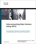
The network design must provide the highest availability for the LAN infrastructure. To achieve this goal, the teaming service or dual-homing should be distributed between different access switches, which in turn should be connected to different aggregation switches, as illustrated in Figure 1-1.
Figure 1-1 Extending the public network.
Private Network Attachment
The private network primarily carries cluster heartbeat, or keepalive, messages. Other server-to-server communications that occur on this private network include the following:
• Cluster data
• Cluster file system data
• Application data (back-end)
The private network is a nonrouted network that shares the same Layer 2 VLAN between the nodes of the cluster even when extended across multiple sites. In a campus cluster environment, heartbeats are sent via the private network from node to node of the HA cluster using a proprietary Layer 2 (nonroutable) protocol. The servers manage the I/O by sending traffic over all interfaces and by preventing traffic from being sent over a failing path. This approach provides resiliency in the event of a NIC failure on a server.
The heartbeat is the most important component of the cluster that uses the private network interconnection. However, if all paths go down for more than 10 seconds (applicable for most HA clusters), a split-brain situation can occur, which prompts the cluster framework to check the number of votes and decide which server or servers will continue as the members in the cluster. Nodes that lose cluster membership assume that they are isolated, and any applications that run on those nodes terminate. Surviving nodes know that the nonsurviving nodes have stopped, and the cluster will then restart the applications.
Although some HA cluster vendors recommend disabling Spanning Tree Protocol (STP) for the private interconnect infrastructure, such a drastic measure is neither necessary nor recommended when using Cisco Catalyst switches. In fact, Cisco has since provided the PortFast feature, which puts an access port into forwarding mode immediately after link up without losing loop-detection capabilities. To avoid connectivity delays, PortFast must be enabled on all access interfaces connecting cluster nodes. This rule also applies to any servers connected to the switch. The IEEE also defines the PortFast concept within the Rapid STP 802.1w standard under the edge port designation. In addition, Cisco supports Per-VLAN Spanning Tree, which maintains a spanning-tree instance for each VLAN configured in the network.
Note
For detailed information about HA clusters, refer to the Windows HPC Server 2008 site at http://www.microsoft.com/HPC/.
For detailed information about STP PortFast configuration to resolve server/workstation startup connectivity delay, refer to the Cisco document Using PortFast and Other Commands to Fix Workstation Startup Connectivity Delays, available at http://tinyurl.com/2e29bw.
For detailed information about designing a network for extended HA clusters, refer to the following Cisco white paper A: “Technology and Networking Guide for High Availability Clusters Extended Across Multiple Data Centers,” at http://tinyurl.com/cb4f3k.
Data Center Interconnect: Legacy Deployment Models
Several transport technologies are available for interconnecting the data centers, each of which provides various features and allows different distances, depending on factors such as the power budget of the optics, the lambda used for transmission, the type of fiber, and so forth.
Consider the features of the LAN and SAN switches that provide higher availability for the data center interconnect (DCI) before considering some of the available technologies. The convergence time required for the application also is important and should be evaluated.
The list that follows describes common transport options:
• Dark fiber: Dark fiber is a viable method for extending VLANs over data center or campus distances. The maximum attainable distance is a function of the optical characteristics (transmit power and receive sensitivity) of the LED or laser that resides in a small form-factor pluggable (SFP) or Gigabit Interface Converter (GBIC) transponder, combined with the number of fiber joins, and the attenuation of the fiber.
• Coarse wavelength-division multiplexing (CWDM): CWDM offers a simple solution to carry up to eight channels (1 Gbps or 2 Gbps) on the same fiber. These channels can carry Ethernet or Fiber Channel. CWDM does not offer protected lambdas, but client protection allows rerouting of the traffic on the functioning links when a failure occurs. CWDM lambdas can be added and dropped, allowing the creation of hub-and-spoke, ring, and meshed topologies. The maximum achievable distance is approximately 60 miles (100 km) with a point-to-point physical topology and approximately 25 miles (40 km) with a physical ring topology.
• Dense wavelength-division multiplexing (DWDM): DWDM enables up to 32 channels (lambdas), each of which can operate at up to 10 Gbps. DWDM networks can be designed either as multiplexing networks that are similar to CWDM or with a variety of protection schemes to guard against failures in the fiber plant. DWDM also offers more protection mechanisms (splitter protection and Y-cable protection), and the possibility to amplify the channels to reach greater distances.
Note
For details about data center transport technologies, refer to Chapter 2 of Data Center High Availability Clusters Design Guide, available at http://tinyurl.com/ct4cw8.
In nearly all of these deployment models, costs associated with deploying and maintaining a dedicated optical network is one of the biggest concerns. Also, there is no STP isolation. Depending on the nature of the problem, issues in one data center will affect other data centers. Another disadvantage is the lack of load balancing across redundant paths due to blocked links in the core network.
Problems Associated with Extended Layer 2 Networks
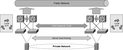
A common practice is to add redundancy when interconnecting data centers to avoid split-subnet scenarios and interruption of the communication between servers, as illustrated in Figure 1-2. The split-subnet is not necessarily a problem if the routing metric makes one site preferred over the other. Also, if the servers at each site are part of a cluster and the communication is lost, mechanisms such as the quorum disk avoid a split-brain condition.
Figure 1-2 Layout of multiple data center interconnect with redundant N-PEs in each data center.
Adding redundancy to an extended Ethernet network typically means relying on STP to keep the topology loop free. STP domains should be reduced as much as possible and limited within the data center. Cisco does not recommend deploying the legacy 802.1d because of its old timer-based mechanisms that make the recovery time too slow for most applications, including typical clustering software.
An extended Layer 2 network does introduce some problems to contend with, however.
STP operates at Layer 2 of the Open Systems Interconnection (OSI) model, and the primary function STP is to prevent loops that redundant links create in bridge networks. By exchanging bridge protocol data units (BPDU) between bridges, STP elects the ports that eventually forward or block traffic.
The conservative default values for the STP timers impose a maximum network diameter of seven. Therefore, two bridges cannot be more than seven hops away from each other.
When a BPDU propagates from the root bridge toward the leaves of the tree, the age field increments each time the BPDU goes through a bridge. Eventually, the bridge discards the BPDU when the age field goes beyond maximum age. Therefore, convergence of the spanning tree is affected if the root bridge is too far away from some bridges in the network.
An aggressive value for the max-age parameter and the forward delay can lead to an unstable STP topology. In such cases, the loss of some BPDUs can cause a loop to appear. Take special care if you plan to change STP timers from the default value to achieve faster STP convergence.
Unlike legacy STP, Rapid STP (RSTP) converges faster because it does not depend on the timers to make a rapid transition. However, STP does not provide the required robustness for large-scale Layer 2 deployments:
• Network stability is compromised as a result of slow response to network failures (slow convergence). Even new spanning-tree developments such as RSTP and Multiple Spanning Tree (MST) assume good-quality physical connections such as dark fiber or WDM connections. These STP protocols are not built to accommodate frequent link-flapping conditions, high error rates, unidirectional failures, or nonreport of loss of signal. These typical and frequent behaviors of long- and medium-distance links could lead to STP slow convergence or even instability.
• The primary reason for multisite data centers is disaster recovery. However, because data centers typically require Layer 2 connectivity, failure in one data center can affect other data centers, which could lead to a blackout of all data centers at the same time.
• A broadcast storm propagates to every data center, which, if uncontrolled, could result in network-wide outage.
• STP blocks links, which prevents load balancing of traffic across redundant paths in the core network.
Note
For understanding and tuning STP timers and the rules to tune them when absolutely necessary, refer to the Cisco document, “Understanding and Tuning Spanning Tree Protocol Timers,” available at http://tinyurl.com/7ppqq.
Summary
This chapter provided an overview of HA clusters, legacy deployment models for interconnecting data centers, and problems related to extending Layer 2 networks. The solutions that this book presents address these issues in more detail and provide guidance for designing and deploying DCI.