Chapter 6. Case Studies for Data Center Interconnect
Data center interconnect (DCI) is attracting attention because it is one of the pillars of generalizing the concept of virtualization across data centers. Both new server middleware usages, which offer clustering for high availability or flexibility for servers’ virtual organization (VMotion), and more traditional requirements for physical server migration increasingly require a capability to extend VLANs (Layer 2 bridging, L2) across data center sites.
This chapter examines two deployments that implement DCI using Virtual Private LAN Service (VPLS) technology. One deployment is a large government organization (GOV) that provides internal networking and data center solutions. The other is an application service provider (OUT) that hosts servers and provides applications to a large customer base.
Case Study 1: Large Government Organization
GOV is a large government organization that provides networking solutions and data center infrastructure to several other government entities.
Challenges
To increase the availability of key applications, GOV’s IT department decided several years ago to implement a server cluster strategy. This strategy provided good application redundancy and scalability and significantly improved GOV’s capability to recover from server and operating system failures.
However, to benefit from new networking features, the implementations required cluster members to reside in the same network subnet. In addition, clusters relied on heartbeats that must run in a dedicated VLAN. To take advantage of current cluster technologies, GOV had to extend most VLANs within each data center.
Furthermore, GOV needed to improve its high-availability capabilities. In addition to handling server and operating system failures, clustering had to provide solutions for situations such as partial data center power failures and site inaccessibility. Addressing these requirements meant extending clusters across multiple sites.
Like many other data centers, GOV’s data centers also began to encounter physical constraints. Insufficient power, limited space, and inadequate cooling posed insolvable issues with server physical organization and operation, which led to GOV not even being able to install a new cluster member when application performance required it.
Solution
To address these issues, GOV determined that it required a solution that included a multisite VLAN extension.
The initial solution was a Spanning Tree Protocol (STP) design that controlled four data centers in a global switching domain. GOV carefully followed best practices for L2 design, but the optical topology of the sites’ interconnection was unable to match standard STP recommendations; dual hub-and-spoke topology and dense wavelength-division multiplexing (DWDM) protection are considered a must for STP. In addition, the size of the STP domain started to increase above any common implementation.
GOV operated its networks using this design for 1 year. During this time, several small failures occurred, which led to unpredicted results. In one instance, for example, a link failure did not report the loss of signal, leading STP to slow convergence. Every heartbeat over every data center timed out; consequently, all clusters experienced a split-brain situation. Resynchronization took more than 1 hour to recover. During this time, all critical applications stopped operating. Other small failures had similar catastrophic effects. As a result, GOV contacted Cisco for recommendations about how to strengthen its network.
Working in partnership with the GOV networking team, the server cluster vendor, and an external consulting team, Cisco recommended a VPLS solution as described in this book.
The solution team also determined to provide Multiprotocol Label Switching (MPLS) features, such as Virtual Routing and Forwarding (VRF), to provide user-group security segmentation, and traffic engineering, to better manage link loads.
After thorough testing and a pilot phase, the solution was deployed in three GOV data centers. A fourth data center was added soon afterward, and the solution is running successfully.
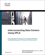
Figure 6-1 illustrates the new GOV solution.
Figure 6-1 Global VPLS architecture.
To build the L3-VPN network and the 10-Gbps MPLS core, GOV selected a Cisco Catalyst 6500 switch with a 67xx line card. This approach allows the easy deployment of VRF within the aggregation layer. L3-VPN extends to all data centers and toward user sites.
To enable the MPLS Traffic-Engineering (TE) feature, the routing protocol had to be link-state-based, so the choice was reduced to either Open Shortest Path First (OSPF) or Intermediate System-to-Intermediate System (IS-IS) routing. In a network of this size, IS-IS and OSPF offer quite similar capabilities, but IS-IS allows a clear demarcation with existing OSPF routing that simplifies deployment. GOV selected IS-IS as its MPLS core routing protocol.
Routing fast convergence is set with a target of a few hundred of milliseconds. Bidirectional Forwarding Detection (BFD) is used to detect long-distance link failure, which allows the system to react in approximately .5 seconds to any nonforwarding link. (GOV plans to include the MPLS Fast-ReRoute [FRR] function in future implementations, with the objective of achieving even more convergence on clear link failures.)
To implement the VLAN extension design using VPLS, the most advanced Network Provider Edge (N-PE) node was the Cisco 7600. Because Cisco 7600 Ethernet Service (ES) cards were not yet available at that time, GOV selected a SIP-600 card to provide 10 Gbps. (An ES card would be the right choice now.)
GOV selected Hierarchical-VPLS (H-VPLS) with Embedded Event Manager (EEM) scripts to provide STP isolation and long-distance link protection.
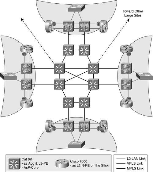
Four data centers required a VLAN extension to allow cluster extension. The solution included the Cisco 7600 N-PE on a stick. Figure 6-2 illustrates the concept of a “node on a stick.”
Figure 6-2 VPLS N-PE on a stick.
VPLS technology was quite new at the time of implementation. The “on a stick” design allowed GOV to avoid the insertion of new devices with the new Cisco IOS Software and new features along the existing L3 path. Because of this, VPLS failure would affect only L2 traffic, not IP traffic.
L2 traffic first passes in a bridge fashion through the aggregation Cisco Catalyst switch, and then is encapsulated in VPLS by the Cisco 7600 N-PE and pushed back to the Cisco Catalyst switch via a MPLS L3 port. Then traffic flows to the MPLS core.
The Cisco 7600 N-PE uses the 67xx LAN card toward the edge. Each ingress port is then encapsulated into a dual VLAN tag using the IEEE 802.1Q-in-Q VLAN tag (QinQ) feature before being forwarded to VPLS. This QinQ encapsulation enables scalability to any number of VLANs. However, QinQ requires the careful management of overlapping inter-VLAN MAC addressees. This issue is analyzed in depth in Chapter 11, “Additional Design Considerations.”
Enterprises should avoid extending network services such as firewalls or load balancers across data centers. In addition, good data center design uses different Hot Standby Router Protocol (HSRP) groups in each data center. These rules were implemented with GOV, where VLAN extension is strictly reserved for issues with multiple data center clusters and not used for other requirements.
In addition, LAN ports are protected from a data-plane storm using storm control for broadcast and multicast, which allows deployments to avoid the propagation of flooding across sites. This issue is also analyzed in depth in Chapter 11.
To enable N-PE backup, GOV deployed EEM scripting. The deployment did not include the Ethernet Virtual Circuit (EVC) feature because LAN port types do not allow it.
VLAN load repartition is performed at the edge by using two 10-Gbps edge ports, with per-VLAN cost balancing.
To manage core load repartition over multiple paths, MPLS-TE was deployed, with each virtual forwarding instance (VFI) targeted to a different path.
Case Study 2: Large Outsourcer for Server Migration and Clustering
OUT is an outsourcer that has deployed L2 DCI.
Challenges
Outsourcers such as OUT require the capability to easily perform add and move on request by individual servers. In addition, space, cooling, and power issues require the frequent reorganization of data centers. Flexibility is therefore a master word for outsourcing services. With the arrival on the market of dynamic server virtualization (VMotion), outsourcers can now operate servers more dynamically and with increased flexibility. Flexibility to move servers requires VLAN extension, but outsourcers are well aware of the strong limitations of L2 bridging in terms of resiliency. VPLS is perceived as a solution that combines flexibility with high availability.
Solution
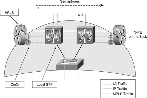
Figure 6-3 illustrates the new OUT virtualized data center.
Figure 6-3 Multisite virtualized data center.
The OUT DCI network was designed to include ten sites interconnected through 10 Gbps over DWDM links.
Outsourcers have strong scalability requirements and must therefore deploy hardened and flexible solutions. Choosing the correct architecture is important. The best choice for N-PE redundancy will be available in the future and will use Inter-Chassis Communication Protocol (ICCP) with multichassis Link Aggregation Control Protocol (mLACP). An EEM-based solution allows immediate deployment and is adaptable to any design topology.
OUT selected the Cisco 7600 with ES40 10-Gbps card to simultaneously perform H-VPLS, VRF, and core routing functions.
OUT chose H-VPLS with EEM for node redundancy. EEM offers a large panel of options detailed in Chapter 9, “EEM-Based Deployment Models.” OUT selected multiple options based on the site architecture:
• EEM option 5 was selected for green-field data centers with Nexus virtual PortChannel (vPC) or with Virtual Switching System (VSS).
• EEM option 4 was selected for existing data centers.
• EEM option 3 was considered, but not yet deployed, for a very old-fashioned data center that does not support scripting into aggregation switches.
OUT considered connections to customer-owned data centers, mainly for migration purposes, but also for cluster extension. Because customer aggregation switches cannot be modified, it was decided to insert a physical small switch (User Provider Edge [U-PE]) per distant customer to perform the MAC-flush script on behalf; this is EEM option 4b, which is also described in this book.
One of the main issues comes from the multitenant aspect of the design. OUT offers its customers hosting for either applications or dedicated physical servers, and sometimes offers dedicated full DC zones. To create secure data centers, OUT selected the Nexus-based virtual data center (VDC) to ensure separation between front-end and back-end areas and to provide management-area isolation. A single VDC is shared between multiple customers, and connection to the 7600 N-PE uses one 10-Gbps port per VDC.
The initial plan was to create one VFI per VDC. This approach would have allowed easy scalability because N-PE would be transparent to the aggregation VLAN. However, sharing the same QinQ bridging domain between customers could result in the overlapping of MAC addresses.
While waiting for future MACinMAC encapsulation (802.1ah), which will be performed at ingress by an ES40 card, it has been decided to allocate one QinQ bridge domain per large customer, and one QinQ domain gathers smaller customers. To accomplish such a dynamic allocation, the Selective QinQ option will be intensively used. This feature allows OUT to identify a set of customer VLANs and encapsulate them in one core VLAN that will be transported using VPLS. Such dynamic encapsulation is a good compromise between scalability and security.
OUT evaluated standard EEM options. However, to improve its convergence timing, OUT asked Cisco to tune scripts to allow active and standby pseudowires in the UP/UP condition. (That is, the alternate path is up and ready but not forwarding traffic until backup.) This configuration is accomplished by tuning the EEM script that inserts and removes the bridge domain condition from the ingress port service instance. To avoid the need to modify the script each time a new customer is inserted, OUT created a set of preprovisioned VFIs.
Load repartition is a key element of the design. With load repartition, multiple parallel links are used to increase intersite throughput. With the Cisco 7600, a VFI is considered as a whole set, and its content is not balanced based on MAC addresses, whether the parallel link uses equal-cost multipath (ECMP) routing or EtherChannel. Load repartition over a parallel links bundle is executed blindly on the last label of the stack, which is the pseudowire (PW) pointing to the remote VFI. Because granularity is per VFI, balancing is poor when the number of VFIs is low, and one link could easily be overloaded while others are almost empty. To avoid this situation, MPLS-TE was implemented to ensure controlled balancing for each VFI.
Figure 6-4 illustrates an efficient way to control balancing on a link bundle.
Figure 6-4 Link bundle balancing using MPLS-TE.
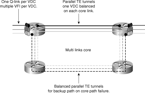
The approach illustrated in Figure 6-4 ensures that, in normal mode, traffic coming into an N-PE at 10 Gbps can find a 10-Gbps path toward the next hop, even in link-failure conditions. Link-overload conditions could occur with complex traffic patterns or if a node fails, so standard DiffServ queuing is applied to protect key traffic. MPLS-TE is also offering measure of end-to-end traffic over the core, which provides a view of traffic patterns so that paths can be adjusted if needed.
Summary
VPLS with N-PE redundancy allows customers to flatten the bridging domain over multiple data centers by using the strongest technology currently available. This approach benefits both the server and application layers because it enables flexibility and availability for
• High-availability extended server clusters
• Virtual machines
• Migration
This flexibility does inherently include some caveats, however:
• The solution is complex and introduces constraints at the networking layer.
• Extension of the broadcast domain might present some storm risk.
Balancing the risks and benefits between implementing VLAN extension and a lack of flexibility for servers led these organizations to select VPLS.