Chapter 4. MPLS Traffic Engineering
As of this writing, Virtual Private LAN Services (VPLS) and Ethernet over Multiprotocol Label Switching (EoMPLS) technologies are the most appropriate methods for extending a Layer 2 VLAN. In most cases, these technologies require enabling MPLS in the core network. In addition, correlated MPLS features such as traffic engineering (TE) and Fast Reroute (FRR) should be considered for improving network transport.
Understanding MPLS-TE
When IP or Label Distribution Protocol (LDP) is the transport mechanism, traffic always follows the Interior Gateway Protocol (IGP) shortest path and benefits from equal-cost multipath (ECMP) balancing.
MPLS Traffic Engineering (MPLS-TE) is based on a different approach. It relies on source routing, in which the headend of the path creates an end-to-end circuit that is based on several constraints. In addition to shortest path, MPLS-TE allows the following constraints:
• Explicit path: Specifies a sequential list of nodes that must be traversed.
• Affinity path: Specifies a path affinity that must match the link affinity attribute.
• Dynamic path: Computes a shortest path first (SPF) topology over a set of metrics other than IGP metrics.
• Dynamic path with bandwidth reservation: Allows reserving the amount of link bandwidth for each MPLS-TE circuit. The headend router determines whether links in the path are able to host circuits. This approach is very useful to build assured circuit topology for sensitive applications like video.
• Preestablished backup path: Allows FRR if a failure occurs.
MPLS-TE enables a new type of interface tunnel (called tunnel LSP or simply TE tunnel) that connects a headend router to a tailend router via the MPLS core.
To create constraint-based LSP, MPLS-TE relies on five main elements:
• Configuration of additional link attributes, which specify the following: TE metric (cost) for dynamic topology SPF 32 bits to qualify a link.
Reservable bandwidth, which decreases dynamically along circuit reservations.
• Link information distribution through SPF (ISIS-TE or OSPF-TE): Floods link attributes across all nodes so that the headend router is aware of the network capability to accept a tunnel.
• Path calculation (CSPF) executed on the headend router: The headend router computes the best available path to match tunnel constraint configuration such as bandwidth, affinity, explicit path, and priority. May specify multiple options lists.
• Path setup (RSVP-TE): The headend router creates the end-to-end LSP using Resource Reservation Protocol (RSVP) signaling, and obtains label allocation along the matching constraints’ core path.
• Forwarding traffic down the tunnel: There are several ways to forward traffic over the tunnel LSP after the tunnel becomes active. VPLS uses per-virtual forwarding instance/pseudowire (VFI/PW) tunnel allocation, in which VFI and PW are VPLS elements.
MPLS-TE is often deployed in service provider networks. However, large enterprises and public organizations that have deployed MPLS have also found this technology useful.
The FRR option is an attractive feature for data center interconnection because it further decreases the convergence time if a link failure occurs. However, complex core topologies require controlled load repartition. Parallel link bundling to increase intersite bandwidth is difficult to accomplish without a tool such as traffic engineering. The following sections discuss FRR and load repartition in greater detail.
Data center interconnect rarely uses the bandwidth reservation paradigm because its topology is often not highly complex. In addition, the percentage of sensitive traffic lost is low. However, with the availability of Fibre Channel over IP (FCoIP) traffic, the tolerance for loss of sensitive traffic is very low.
Fast Reroute
When protecting the MPLS core links and nodes, it is common to tune the routing protocol (IGP) to achieve a few hundred of milliseconds of convergence time on failures. Nevertheless, even when the SPF initial-wait timer (SPF init) is aggressively reduced, the IGP recovery times are still in the order of magnitude higher when compared to preset techniques like FRR, particularly if you have built a complex MPLS core network in which VPLS nodes, the Network-facing Provider Edges (N-PEs), do not directly interconnect.
FRR relies on a preconfigured backup path that is used immediately if a link or an adjacent node fails. The system executes the repair, called a local repair, when it detects this failure. In comparison, IP routing requires recomputation of an alternate path by the rerouting node when it detects a failure.
Load Repartition over the Core
When multiple paths between two N-PEs are not equal in cost, which primarily occurs when the core is not full, meshed, IGP does not allow traffic load balancing. In this case, you can rely exclusively on VLAN load repartition at the edge to balance traffic on two N-PEs and thus on two paths in the core. Alternatively, you can build several MPLS-TE circuits from one N-PE and balance VFI from the N-PE.
Load Repartition over a Parallel-Links Bundle
Repartition of encapsulated traffic is complex because nodes do not have direct access to encapsulated content. Therefore, you should understand the following load-balancing algorithms that most N-PE and core nodes apply to a parallel-links bundle:
• Basic MPLS load balancing: The maximum number of load-balancing paths is eight.
The switching engine on Cisco 7600 series routers and Catalyst 6500 series switches, called the policy feature card (PFC), forwards MPLS labeled packets without explicit configuration. If the packet includes three labels or fewer and the underlying packet is IPv4, the PFC uses the source and destination IPv4 addresses. If the underlying packet is not IPv4 or if it includes more than three labels, the PFC parses down as deep as the fifth or lowest label and uses it for hashing. This stack depth limit is for the Cisco 7600 router and may be different for other devices.
• MPLS Layer 2 VPN load balancing: Load balancing is based on the PW label in the MPLS core if the first nibble (4 bits) of the MAC address in the customer Ethernet frame is not the value of 4.
A VFI is considered to be a whole set, and its content is not balanced based on MAC addresses, regardless of the parallel link grooming, equal-cost multipath (ECMP), or EtherChannel (EC). Depending on the line card interfaces used as core links, EC may not be supported. Load repartition over a parallel link bundle with EC and ECMP hashing is executed on the last label of the stack, which points to the VFI. Consequently, when there are few VFIs configured, unequal distribution of traffic might occur across multiple links in the bundle. To overcome such a situation, you can implement MPLS-TE to ensure per-VFI load repartition over multiple links in a bundle.
Implementing MPLS-TE for Traffic Repartition over Parallel Links
This section walks you through the steps required to implement MPLS-TE. Optionally, FRR can be enabled to protect MPLS-TE tunnels.
MPLS-TE can be used to optimize network usage in several ways, but with data center interconnect, a common usage is the controlled load repartition of traffic over bundled links.
Implementing traffic balancing per-VFI over bundled links can be complicated. To help understand the required configuration, consider inter-N-PE connectivity between data centers using a bundle of three links.
The goal is to statically map VFI traffic over a link in the bundle and avoid dynamic allocation that may overload one of the links. This mapping must be effective in normal conditions and even in the case of a link failure.
Figure 4-1 shows a site that uses nodes 1 and 2 to connect using two set of bundled links toward a remote site, which uses nodes 3 and 4.
Figure 4-1 Sites interconnected via link bundles.
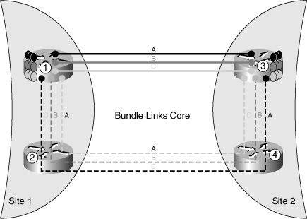
Each node is connected with two other nodes through a bundle of three links (links A, B, and C) to increase intersite bandwidth. Consider the traffic from node 1 to node 3. To allow controlled traffic distribution on the bundle, you have to create three MPLS-TE tunnels from node 1 to node 3 (tunnels A, B, and C). The tunnel A primary path is through the direct link A that connects nodes 1 and 3, and the secondary path is through the three links joining nodes 1, 2, 4, and 3. In normal mode, a VFI attached to tunnel A will use the direct link A joining nodes 1 and 3; other VFIs will use links B or C. If link A between nodes 1 and 3 fails, tunnel A will be rerouted through the secondary path, which is using only type A links, and so will not disturb the VFI using type B or type C.
This behavior differs completely from uncontrolled balancing with ECMP, where, during link A failure, traffic passes through the direct links B or C.
Example 4-1 shows how to set up a TE tunnel from node 1 to node 3 (tunnel 3) through either direct link A when active, or through alternate link A via nodes 2 and 4 when in backup mode.
Example 4-1 Setting Up MPLS-TE Tunnels
The following sections document the steps to implement controlled load repartition of traffic over bundled links using MPLS-TE.
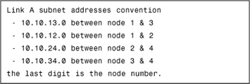
Enable TE
Example 4-2 illustrates a configuration that enables TE globally, per interface and under the SPF IGP.
Create MPLS-TE Tunnels and Map Each VFI to a Tunnel LSP
To balance VFI traffic, first create an MPLS-TE tunnel and map this tunnel to a VFI. To attach the VFI, create a PW class in which all VFI options are listed, as shown in Example 4-3.
Example 4-3 Balancing VFI Traffic
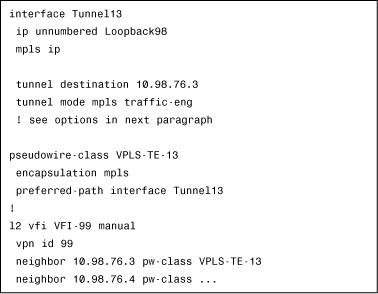
The preferred-path command provides options for strictly or loosely tying a VPLS PW to a TE tunnel. If a PW is strictly tied, whenever the tunnel fails, the PW also goes down. On the other hand, the loose option allows PW to be active even when the TE tunnel fails. Therefore, the loose option is preferred.
Explicit-Path Option
When the network topology is not too complex, as is generally the case for a data center core, TE can be managed easily through explicit-path configuration.
There are three ways to create an explicit path:
• next-address: The next-address option includes the following characteristics:
• Allows listing in hop-by-hop sequence all for nodes or links that the path passes through. Each node or link of the path must be listed.
• In link mode, the next address is a link subnet. In node mode, the next address is the IGP MPLS-TE router ID. So, if multiple parallel links exist between two nodes, the tiebreaker is dynamic balancing.
• The goal of this design is to strictly control traffic repartition over links. In this case, select link mode and use the link subnet address as the next address.
• next-address loose: The next-address loose option has the following characteristics:
• Allows specifying an intermediate node that the path passes through. SPF dynamically builds a path before and after this node.
• The previous address (if any) in the explicit path need not be connected directly to the next IP address.
• exclude-address: Excludes an address from subsequent partial-path segments. You can enter the IP address of a link or the router ID of a node.
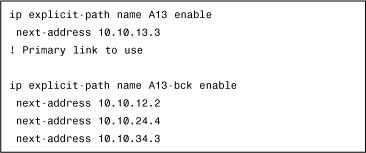
Example 4-4 shows how to configure explicit-path sequences.
Example 4-4 Configuring Explicit-Path Sequences
Example 4-5 demonstrates how to specify tunnel-path options.
Example 4-5 Specifying Tunnel-Path Options
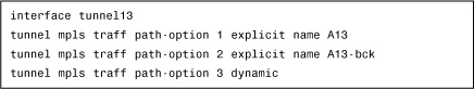
In Example 4-5, if the direct link A between nodes 1 and 3 is active, the TE LSP and the VFI traffic passes through. If this link goes down, traffic routes through an alternate path A, even if the other direct links are active (B and C). The last path option specifies that if no path A is available, the tunnel is allowed to pass through any other link. If this option had not been enabled, the TE tunnel would have failed.
Adding FRR to Explicit Option
FRR increases the efficiency of rerouting if a failure occurs. This efficiency becomes more apparent in a complex network topology.
To compare the efficiency of FRR with IP rerouting, consider the following cases:
• IP versus FRR link protection: When a link failure occurs, FRR reacts in just a few milliseconds to swap primary traffic to the backup tunnel, whereas IP rerouting must wait for the SPF init delay. When the network topology and link type are simple, the SPF init can be lowered to 20 ms or less. In this case, the IP rerouting efficiency is close to that of FRR.
Configuring FRR is much more complex than configuring IGP fast convergence. Therefore, consider FRR when the core is complex and the IGP SPF init timer cannot be lowered any further without compromising network stability.
• LDP versus FRR: Data center interconnect Layer 2 traffic is transported by MPLS and not by IP. Therefore, in this situation, compare IGP + LDP to FRR instead of IP to FRR. IGP+LDP convergence takes some time to rewrite labels and to synchronize IGP and LDP, so IGP+LDP can take upward of tens of milliseconds to converge. On the other hand, FRR ensures convergence in milliseconds. Depending on the application’s sensitivity to loss, this reduction in convergence time that FRR provides may be valuable.
• MPLS-TE RSVP convergence versus FRR: When MPLS-TE is selected for load repartition, either for path balancing or for bundle balancing, compare RSVP convergence to FRR instead of IGP efficiency to FRR. In this case, regardless of the core topology, RSVP convergence time is much higher than FRR convergence. Therefore, FRR is recommended when MPLS-TE is already deployed for load balancing traffic.
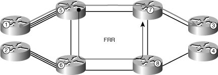
Figure 4-2 shows the implementation of FRR in a square topology.
Figure 4-2 FRR implementation for link protection.
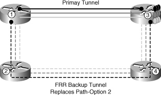
A backup tunnel for an existing primary tunnel must be configured by using FRR instead of a secondary path-option, as shown in previously Example 4-5. The configuration in Example 4-6 shows how to configure a backup tunnel so that it is active and ready for use if a failure occurs.
Example 4-6 Presetting a Backup Tunnel
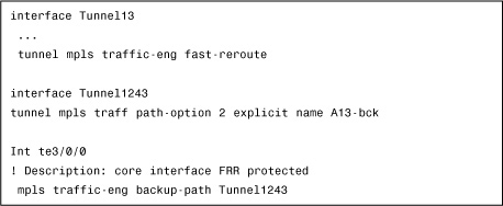
FRR LSP is always active and does not require any recomputation after convergence.
Figure 4-3 illustrates the application of FRR when using core nodes. FRR is typically configured to protect sensitive links, which are most often connecting core routers.
Figure 4-3 FRR implementation in the core.
In the preceding configuration examples, FRR was restricted to link protection. This approach is simple and effective because it allows the use of nonprotected dense wavelength-division multiplexing (DWDM) links for data center interconnection while maintaining fast convergence and protection. In addition, FRR can be configured to protect against core node failures. Although it is appealing, the configuration for protection from node failures is complex.
Affinity Option
When the network topology is simple, explicit-path configuration is easy and comprehensive. If this configuration does not provide the desired result, you can use the MPLS-TE feature called affinity. This feature provides attributes to every core link and gives the MPLS-TE tunnel an affinity to those attributes.
The affinity is represented by 32-bits per mask. Each bit defines an attribute. These attributes have no predetermined significance and are free for interpretation.
For example, the affinity for link type A could be represented by the value 2 (0x10).
A tunnel that is to be configured on a link type A would need to specify affinity = 0x10, with an optional mask of 0x11. The mask specifies which bits to check when the attribute word has multiple meanings.
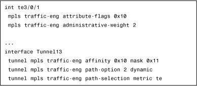
MPLS-TE computes path calculation (PCALC) to determine the best path among the type A links. It is a good practice to define a TE-dedicated metric to break a tie among possible paths.
The configuration in Example 4-7 shows how to use affinity to build a tunnel over type A links without having to list every hop via the explicit-path option.
Adding FRR to Affinity Option
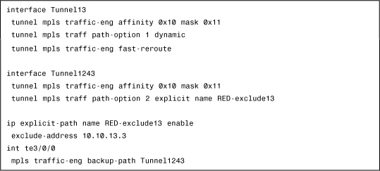
FRR can be added to the configuration in Example 4-7 to protect a primary tunnel via a backup tunnel built on affinity.
The configuration in Example 4-8 shows how to assign the FRR tunnel the same type A affinity as that of the primary tunnels, and specifies that this backup tunnel must exclude the link that it protects.
Example 4-8 Adding FRR to Protect the Primary Tunnel
Summary
Traffic engineering is useful for overcoming limitations of Layer 2 VPN encapsulations, primarily in the areas of load repartition and link bundling. MPLS-TE can be combined with MPLS FRR to achieve fast convergence times.