
This chapter will walk you through the process of creating, managing, and printing sheets. In our industry, sheets are still the end result of a project. They need to be signed and stamped as legal documents and therefore are a very important part of the process.
You will also learn how to organize sheets. This will help you keep your Revit project better organized so that the whole team can function within your organization in a timely manner.
In this chapter, we'll cover the following:
About titleblocks and sheets
Setting up sheets
Organizing sheets
Exporting sheets and DWF
When it comes time to print your drawings in Revit, you need to create sheets. These are the individual pages in your construction document set. On these sheets you will drop views such as plans, elevations, sections, details, and so on. You will have one sheet for each construction document page, but you can have multiple project views or schedules on each sheet view. It is important to note, though, that once you place a view (plan, section, detail, schedule, and so on) on your sheet, you can't place that view on another sheet.
To help define your sheets, you will want to create a titleblock. Titleblocks define the size and appearance of a drawing sheet. Titleblocks are families; you use the Family Editor to create them. In the titleblock you can specify the sheet size, add borders or logos, and add intelligent labels to control the display of information.
Revit includes several titleblock families that can be used to create custom titleblocks to suit your project needs. Your organization probably already has existing titleblocks from other CAD programs that you want to continue to leverage. In this chapter, we will walk you through the steps of creating a new titleblock and using existing CAD data as an underlayment to speed the titleblock creation process.
The titleblock is the template for the sheets. Table 14.1 describes the various Revit elements that are used to define the titleblock.
Table 14.1. Titleblock elements and tools
ELEMENT/TOOL | DESCRIPTION |
|---|---|
Family types | Allows you to define different properties of the family. For example, you might have one titleblock family that contains different types for the different titleblock sizes and usage. |
Lines | Used to create the border and lines that divide the titleblock into different areas. |
Symbols | 2D drawing symbols such as a north arrow or a company logo that has been created with Revit geometry. |
Masking region | Used to mask or hide a region in the family. |
Filled region | Used to create a 2D view–specific graphic. |
Dimensions | Used to show and control distances between the various titleblock elements. |
Text | Adds text to the titleblock. Text can be modified only when in the Family Editor. |
Reference lines | Used as reference geometry and can be used to align other titleblock elements. Does not print. |
Labels | Data field that is used to display specific parameters when the titleblock is loaded into the project. Unlike text, a label will change as the project parameter associated with it changes. Typical label parameters are Project Name, Project Number, Sheet Name, Sheet Number, and Scale. |
Images | Allows you to place an image such as your company logo into the titleblock. |
In this exercise, you will create a very basic titleblock using CAD geometry as an underlay:
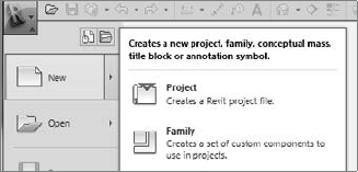
Go to the application menu, and choose New

Select D – 36 × 24 (
A3 metric.rft), and then click Open.The Family Editor is now opened. In the drawing area, you are presented with a blank canvas with the exception of four lines that represent the extents of your 36″ × 24″ sheet (420 × 297). In the next sequence of steps, you will import the CAD file of your company titleblock to use as your underlay.
On the Insert tab's Import panel, click Import CAD.
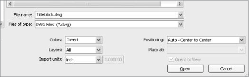
Browse to the source file
Titleblock.dwg, available from this book's web page (www.sybex.com/go/introducingrevit2011), as shown in Figure 14.2.In the Import CAD Formats dialog box, set Import Units to Inch, and click Open.
Now that you have imported the CAD file (Figure 14.3), you can trace the CAD lines using Revit lines. This will create the framework of your titleblock.
On the Modify | Place Line tab's Draw panel, click the Pick Lines tool

Select each of the lines in the CAD file to create Revit lines.
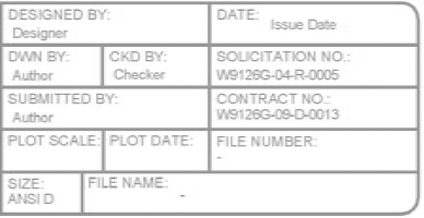
Once you have created your Revit lines, you have your framework of your titleblock, and you can start adding text to identify the different sections. In the next steps, you will use the Text tool to create static information to display information such as the identifier for the Date, Plot Scale, CKD BY, File Number, and other fields (Figure 14.4). Later you will use labels to provide the display parameter information for the previously listed fields.
If you did not complete the previous steps, you can open the
Titleblock Add Text.rfafamily to continue with this section.

On the Home tab's Text panel, click the Text tool.
In the Properties palette, click the Edit Type button. You are going to create a new text type.
In the Type Properties dialog box, click the Duplicate button.
Name the new text type 1/16″ Arial (1.5mm Arial).
Change the text size to 1/16″ (1.5mm).
Click OK to close the Type Properties dialog box.
Using Figure 14.4 as a reference, you will create Revit text for each text item. Select a left attachment point and a right attachment point for text insertion.
Make sure that the horizontal alignment on the Modify | Place Text tab's Format panel is set to Left.
Add text for the field descriptions. Use Figure 14.4 as a reference or create text for the cyan color text in the imported CAD file.
When creating a titleblock, it may also be necessary to import an image file of your company or client logos. Revit provides you with a simple means for handling this task.
On the Insert tab's Import panel, click Image. This will open the Import Image dialog box.
Navigate to the files from the book's companion page (
www.sybex.com/go/introducingrevit2011), and openCompanyLogo.jpg.Place this logo in the top-right box in your titleblock.
Repeat steps 1–3, and load
ProjectLogo.jpg. Place this just below the project title.
Note
Limit the number of images that you import into your project. Revit provides a means for managing imported images. You can manage images from the Insert tab's Import panel by clicking the Manage Images button. The Manage Images dialog box lists all the images used in the project including any rendered images. Using this dialog box is the only way you can delete an image from the project. Selecting and deleting an image in a view does not remove the image from the project, only from that view.
Now that you have created your field description text, you can use the Label tool to fill out the information. You use labels to read information from the project and automatically display that information. These are some examples of data that you can use for display information:
Project name
Sheet name
Sheet number
Scale
If you did not complete the previous steps, you can open the Titleblock Add Label.rfa family to continue with this section.
On the Home tab's Text panel, click the Label tool.
In the Properties palette, click the Edit Type button. You are going to create a label type.
In the Type Properties dialog box, click the Duplicate button.
Name the new label style 1/16″ Arial (1.5mm Arial).
Change the text size to 1/16″ Arial (1.5mm).
Click OK to close the Type Properties dialog box.
Create another text style call 5/16″ Arial Bold (8mm Arial Bold) following steps 2–6.
In the next steps, you'll create a label that will populate your titleblock with the sheet number.
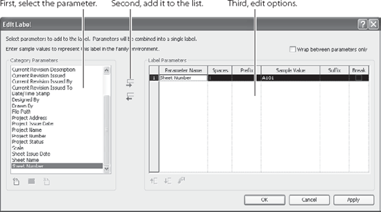
Click a point for the location for the sheet number. This will cause the Edit Label dialog box to open (Figure 14.5).
In the Category Parameters section, click the Sheet Number parameter.
Click the Add Parameter(s) To Label icon to add it to the Label Parameters list.
Click OK to close the Edit Label dialog box.
In the Properties palette, set Horizontal Alignment to Center.
Move the label you just created to properly position it.
Note
In the Edit Label dialog box, you can add more than one parameter to a single label. Sheet Number is a good example where you need to utilize only a single parameter. Project Location, which could consist of a street address, city, state, ZIP code, and phone number, is a good example where you could utilize multiple parameters.
In the next steps, you will use the 1/16″ Arial (1.5mm Arial) label to create a label for the view scale.
On the Home tab's Text panel, click the Label tool.
In the Properties palette, make the 1/16″ Arial (1.5mm Arial) label.
Locate the SCALE: description field in the titleblock, and click below that. This is where you will display the name of the person checking the sheets. The Edit Label dialog box will open.
In the Category Parameters section, click SCALE parameter.
Click the Add Parameter(s) To Label icon to add it to the Label Parameters list.
Click OK to close the Edit Label dialog box.
In the Properties palette, set Horizontal Alignment to Left.
Move the label you just created to properly position it.
Note
When you load the titleblock into our project and create a sheet, if you have only one view on the sheet, the scale of that view will be displayed. If you have multiple views in a sheet, the Scale parameter will display As Indicated.
When you create a titleblock, you may need to display information in which Revit does not have a predefined parameter in the Category Parameters list, as shown in Figure 14.5. An example of this might be CONTRACT NO. Now you could populate the titleblock with the contract number by using the Text tool, but in the next example, you are going to use the Label tool. This will enable you to populate this information by filling out the Project Information fields. This information can be modified within a project by selecting the Manage tab's Settings panel and clicking Project Information. In the next steps, you will create the CONTRACT NO label.
To accomplish this, you need to create something called a shared parameter. Shared parameters are parameters that you can create to add to your families or project and then share that parameter data with other families or projects. These shared parameters will allow you to add specific information that is not already defined in the family file or project template. We are just going to skim the surface of shared parameters. Consult the online help for more information on using shared parameters.
The first thing you need to do is to create a shared parameter file:
On the Manage tab's Settings panel, click Shared Parameters. This will open the Edit Shared Parameters dialog box (Figure 14.6).
Click the Create button to create a new shared parameter file.
In the Create A Shared Parameter File dialog box, specify a filename and location to which to save your file.
In the lower-right corner of the dialog box, under Groups, click the New button.
In the New Parameter group, specify Titleblock.
On the middle-right side of the dialog box, under Parameters, click the New button.
In the Parameter Properties dialog box, enter the following information:
Name: Contract Number
Discipline: Common
Type of Parameter: Text
Click OK twice to close the Parameter Properties and Edit Shared Parameters dialog boxes.

Now that you've created your shared parameter for the contract number, you need to tie that to your label. Often it is easier to copy an existing label and modify the copy. We will demonstrate that method:
Locate the Plot Scale label that you created in the previous steps, and select it.
On the Modify | Label tab's Modify panel, click the Copy button.
Select the start and end points (Figure 14.7).

In the Edit Label dialog box, remove Scale by selecting it and clicking the red arrow pointing left.
Because the Category Parameters section does not have a Contract Number parameter, you need to create this parameter.
At the bottom of the Category Parameters section, click the Add Parameter button.
In the Parameter Properties dialog box, click the Select button. This will allow you to select a shared parameter.
In the Shared Parameters dialog box, in the Parameter group make sure that Titleblock is selected.
Under Parameters, make sure that Contract Number is selected.
Click OK twice to close the Parameter Properties and Shared Parameters dialog boxes. Notice that in the Category Parameters section, Contract Number has been added.
In the Category Parameters section, click the Contract Number parameter.
Click the Add Parameter(s) To Label icon to add it to the Label Parameters list.
Click OK to close the Edit Label dialog box.

At this point you can change properties such as the justification for the labels and their positioning. One last thing to consider is the width of the label. When the information is larger than the width of the label, Revit will automatically wrap it and add a line below. To control the width, simply select the label and drag the blue dots on each side to the appropriate location.
You can experiment with adding additional text, images, or labels to the titleblock. When you are done using the CAD file as a background, it is very important that you remove that from the family. Leaving the CAD geometry in the Revit family just increases the file sizes and will require you to make additional visibility changes to hide the imported file. To delete the imported CAD file, follow these steps:
Select the imported CAD file. Since you have Revit geometry on top of an imported CAD file, selecting might be difficult. Remember to use the Tab key to cycle through elements that your mouse pointer is hovering over.
With the imported CAD file selected, hit the Delete key.
Save the titleblock using the name
Titleblock SP.rfa.
Now that you have created the titleblock with a shared parameter, you need to load it into a project for testing. You will start by opening, loading your titleblock family, and setting up the shared parameters to populate the titleblock labels.
Open the Advanced Sample Project that ships with Revit. You could also open any project that has sheets already created.
Load
Titleblock SP.rfainto the project:If you did not complete the previous steps, you can load the
Titleblock SP.rfafamily. From the Insert tab's Load From Library panel, click the Load Family button. Navigate to the files from the book's web page (www.sybex.com/go/introducingrevit2011), and open theTitleblock SP.rfafamily.If you have been following along, save the titleblock with the name
Titleblock SP.rfa. On the Home tab's Family Editor panel, click Load Into Project. If you have multiple projects or families open, make sure you select Advanced Sample Project.
Working in the Advanced Sample Project, in the Project Browser under Sheets (All), double-click sheet A1 – Floor Plan. This will open the sheet in the drawing window.
Select the titleblock, and then in the Properties palette change the type to Titleblock SP. When you do this, the floor plan will no longer fit inside the titleblock.
Select the view in the titleblock.
In the Properties palette, change View Scale to 1 : 200.
In the next steps, you will make sure that the project is pointing to the correct shared parameter file that you created earlier and then tie those shared parameters to the project.
From the Manage tab's Settings panel, click Shared Parameters. This will open the Edit Shared Parameters dialog box (Figure 14.8).
Click the Browse button, navigate to the files from the book's web page (
www.sybex.com/go/introducingrevit2011), and open theC14-SP.txtfile.Click OK to close the Edit Shared Parameter dialog box.
You will now tie the shared parameters to your project parameters. On the Manage tab's Settings panel, click Project Parameters. This opens the Project Parameters dialog box (Figure 14.9), which lists all the project-specific parameters that are available to elements within the project.
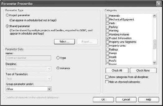
Click the Add button. This will open the Parameter Properties dialog box (Figure 14.10) where you can define project parameters that are specific to the project.
Under Parameter Type, click the Shared Parameter radio button, and hit the Select button. This takes you to the Shared Parameters dialog box where you can select which shared parameters you want to use to create a project parameter.
Select the Contract Number parameter, and click OK to close the Shared Parameters dialog box.
In the Parameter Properties dialog box, set the following:
Set Group Parameter Under to Other.
Select the Instance radio button.
Under Categories, select Project Information.
Click OK to close the Parameters Properties dialog box. In the previous step, you set the Contract Number parameter to display in the Other parameter group, you set the Contract Number parameter to be an Instance parameter, and you assigned the Contract Number parameter to be associated with the Project Information category.
Repeat steps 5–9 for Issue Date, Plot Date, and Project Title.
Click OK to close the Project Parameters dialog box.


The new parameters can now be used to populate your title-block. To add data to these parameters, you need to open the Project Information dialog box (Figure 14.11). You can do this by going to the Manage tab's Settings panel and clicking the Project Information button
Now that you have a basic titleblock framework complete, you can further enhance it by including a revision schedule. Revit provides you with some flexibility in regards to the information you display.
The revision schedule is placed directly within the titleblock. It behaves exactly like a regular schedule and will read the revision and sheet issue information from the project.
The first thing you need to do is create a revision schedule:
Open the
Titleblock RS.rfafamily from among the downloads that accompany this book (fromwww.sybex.com/go/introducingrevit2011).
The first tab, Fields, allows you to select the fields that you want to use in your revision schedule. This example will use the following:
Revision Number
Revision Description
Revision Date
Issued by
On the right side of the dialog box under Scheduled Fields (In Order), you have an extra field called Revision Sequence. You need to remove this from the schedule.
Select the Revision Sequence field. Then, in the top middle of the dialog box, click the <--Remove button. This will remove the Revision Sequence field from the schedule.
Select the Issued By field in the Available Fields listing, and then click the Add--> button.
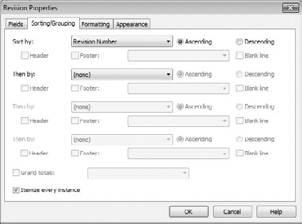
Click the Sorting/Grouping tab. Here, you can use parameters to sort/group your schedules. In this example, you will sort by revision number to keep your revisions organized. As shown in Figure 14.13, in the drop-down field next to Sort By, select Revision Number.
At the bottom of the dialog box, select the Itemize Every Instance check box. This will ensure that all instances of an element in individual rows are displayed.
The next tab is the Formatting tab (Figure 14.14). This allows you to replace the default name for the column header.
This schedule will be labeled as a revision schedule, so you can remove the word Revision from all three fields. Edit the Heading field and the Alignment drop-down for each field, as shown in the following list:
Fields
Heading
Alignment
Revision Number
Rev
Left
Revision Description
Descrip
Center
Revision Date
Date
Right
Issued by
IB
Right
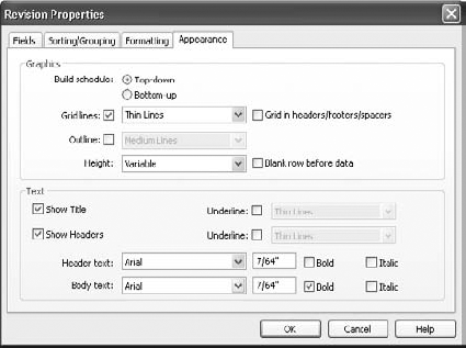
The next tab is the Appearance tab (Figure 14.15). This allows you to change the display of your revision schedule. In this example, you are going to turn off the grid lines and outlines of the schedule and use bold for the body text.
In the Graphics section of the dialog box, deselect the Grid Lines check box; this will prevent grid lines from being drawn. Also deselect the Outline check box.
In the Text section of the dialog box, to the right of Body Text, select the Bold box.
Change the Header Text and Body Text sizes to 7/64″. This will ensure that the revision schedule rows fit with the titleblock revision schedule geometry.
Click OK to close the Revision Properties dialog box. You will then be taken to a view of the revision schedule. Because you are working with a titleblock family in the Family Editor, there will be no information to display.
Close the Revision Schedule view.
You have made some basic changes to your revision schedule including changing the fields that are displayed, how the information will be sorted, the formatting of the data, and how the schedule will look. You can now place the revision schedule on the sheet.
In the Project Browser, expand the View (All).
Under Schedules, select and drag the revision schedule from the Project Browser onto the sheet.
Click and place the revision schedule just below your company logo.
Select the revision schedule. On the Options bar, in the Rotation On Sheet drop-down, select 90 Degrees Counterclockwise.
Use Figure 14.16 as a reference to move the schedule.
You will notice that the revision schedule won't snap to anything, so you will need to approximate the placement. Start by placing the left side. Remember that you can nudge it. To adjust the widths of the columns, select the revision schedule (Figure 14.17) and drag the blue triangles at the top of the schedule to align with the grid lines in the titleblock.
You also need to define the overall height of the revision schedule. Drag the blue dot up to meet the bottom of the revision schedule area in the titleblock. This will define the bottom boundary.


You have finished with your creation of the titleblock. You can now save the family by going to the application menu and selecting Save As
In this section, you'll look at how to create new sheets and how the page setup works. You'll learn to manage sheets to keep a project organized and easy enough for all team members to follow.
Open the source file
rac_basic_sample_project.rvt, which can be found on inc:Program FilesAutodeskRevit Architecture 201ProgramSamples, which was installed with Revit Architecture 2011.Save the file and called it
CreateSheets14.rvt.
To first create a new sheet, you need to load the titleblock. Revit provides multiple methods for loading families into a project. One of the easiest is to drag the family into Revit from Windows Explorer. You can also use the Load Family tool.
From the Insert tab's Load From Library panel, click the Load Family button.
From the chapter's companion files, open the
E1 30 × 42 Horizontal.rfa(orA0 metric.rfa) family.Adding a sheet can be done in several ways. Use one of these two methods:
Either of these actions will open the New Sheet dialog box, where you can select the titleblock you are going to be using. Make sure that E1 30 × 42 Horizontal : E1 30 × 42 Horizontal [A0 metric] is selected. (In either method, if you don't see the titleblock, then you will need to load. Click Load and resume with step 4.)
Click OK in the New Sheet dialog to create a new sheet.
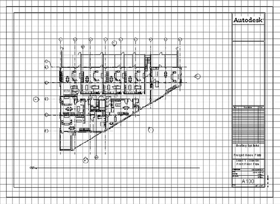
The first sheet is now created and displayed in the drawing window. Notice that Revit automatically gave the sheet a default name and number. Chances are this is not what you want to use. To modify that information, right-click the sheet in the Project Browser, and select Rename. This will open the Sheet Title dialog box where you can change the sheet name and number.
Change the sheet number to A100; change the sheet name to Overall First Floor Plan.
In the next step, you are going to close the Sheet Title dialog box. Prior to doing this, in the drawing window and Project Browser, notice the current sheet name and number. When you click OK, Revit will rename everything for you automatically.
Click OK to close the Sheet Title dialog box.
Repeat steps 3–7, creating another sheet:
Sheet number: A101
Sheet name: Overall Second Floor Plan
Now let's update the Project Name value. Revit Architecture again provides you with multiple methods to accomplish this. The first method is to click the Project Information button on the Settings panel of the Manage tab. An alternate method is to select the titleblock and then click the Project Name value; this allows you to directly edit the text.
Using either of those methods, change the following information:
Project Name: Stanley Office Building
Project Number: 100.5698 AB JX
Date: June 10, 2010
Drawn By & Checked By: Your Name
Owner: Green Development
Now go to the Manage tab's Setting panel and click Open Project Information; verify the value for Project Name (Figure 14.18). That confirms that the information is bidirectional.

The next task is to place views on sheets, for which Revit provides two methods. The first process is actually really simple: drag and drop a view from the Project Bowser on to the sheet.
In the Project Browser, make sheet A 100 – Level 1 – Floor Plan active.
Under Floor Plans, drag the Level 1 floor plan onto the sheet.
Once your mouse pointer is in the drawing window, you can release the left mouse button. Your cursor will change to a preview of the extents of the view. You use this as a reference. Locate where you would like to place the sheet within the titleblock and click.
The second method is just as easy:
In the Project Browser, make sheet A101 – Overall Second Floor Plan active.
On the View tab's Sheet Composition panel, click the View button. This opens the Views dialog box (Figure 14.19).
Within the dialog box, select the Floor Plan: Level 2 view.
Click the Add View to Sheet button.
Using the extent of the view as a reference, place the view on the sheet.

Notice that Revit automatically creates a viewport with a view title and fills the value for Scale in the titleblock.
Since your view was set at ⅛″ = 1′−0″, Revit automatically sized the view appropriately, but if you needed to use a different one, there are several ways you can change the view after placement:
You can go back to the Floor Plan: Level 1 and change the scale directly in the view.
You can right-click the Floor Plan: Level 1 view in the Project Browser and in the properties change the View Scale value.
You can right-click the view on the sheet and select Activate View. You will still be working in the context of the sheet, but you will work as if you were back to the Floor Plan: Level 1 view, giving you access to the scale. (To return to the sheet, right-click again and select Deactivate View.)
To change the location of the view title, simply select it and drag it. If you have more than one view on the sheet, the view title will snap to the other ones for an easier alignment.
To change the length of the line in the view title, you need to select the viewport, not the view title. You will then see blue dots at each end of the view title.
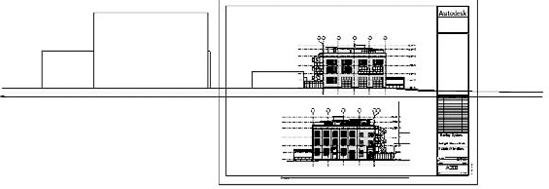
In this section, we'll discuss crop regions. Crop regions define the boundaries of a project view. For example, in Figure 14.20 two elevation views are shown. The top view does not have a crop region defined, and view extents are defined by the geometry in the model. The bottom view, however, has had a crop region defined so that you limit and define how much of the view will be displayed. In the following section, you'll create two new views for your building elevations and then drop elevation views on the sheets. Then use the crop region function to alter the extents of the view.
From the View tab's Sheet Composition panel, click the Sheet button.
In the New Sheet dialog box, make sure that the E1 30 × 42 Horizontal : E1 30 × 42 Horizontal [A0 metric] is selected.
Rename the new sheet Exterior Elevations.
Change the sheet number to A200.
Repeat steps 1–4 creating sheet number A201, and also name it Exterior Elevations.
Make sheet number A200 active.
Add the West and East elevations (building elevations) to the sheet, placing the West elevation above the East.
Notice in Figure 14.20 that the West elevation (top) extents are much greater than those of the East elevation (bottom). You will use the crop region function to alter the extents of the West elevation view so those they are similar to those of the East elevation view.
Select the top view (West elevation). You need to make some changes to the model view; rather than switching to the West elevation view, you will make this view active on the sheet. This will allow you to make changes and use the East elevation and titleblock as references.
Right-click and select Activate View. You can also make the view active by clicking the Activate View button from the Viewport panel on the Modify | Viewports tab.
In the Properties palette under Extents, select the check boxes for Crop View, Crop Region Visible, and Annotation Crop. Crop region can also be turned on and off by clicking the Show Crop Region button on the View Control bar.
Figure 14.21 shows an example of a crop region with the model and annotation crop regions on. Crop regions have two main components:
- Model crop
Crops model elements, detail elements, section boxes, and scope boxes at the model crop boundary. Visible crop boundaries of other related views are also cropped at the model crop boundary.
- Annotation crop
Crops annotation elements when they touch any portion of the annotation element. For example, if you have a tag and the annotation crop is crossing that tag, then the tag information will not be displayed. This is done to prevent partial annotations.
To adjust the crop region, drag the blue control grips until the West elevation has similar extents to the East elevation. If you want to specify an explicit size for the crop region, then click the Size Crop button on the Crop panel on the Modify | View tab. This provides you with options to control the width and height of the model crop and to adjust the annotation crop offsets from the model crop.
When you are done, right-click in the drawing area, and select Deactivate View.
Adjust the view title so it is appropriate for the new view extents.
Make sheet number A201 active. Add the North and South elevations (building elevations) to the sheet, placing the North elevation above the South. Adjust the model crop and view title as needed.

Note
The crop region won't print by default.
In this section, we'll discuss aligning views on sheets. You can continue to use the model from the previous section; or open the source file rac_basic_sample_project.rvt, which can be found on in c:Program FilesAutodeskRevit Architecture 201ProgramSamples, which was installed with Revit Architecture 2011. Save the file and call it CreateSheets14.rvt. Create a new sheet and name it A100.
You are now going to add guide grids to the sheets to align views on different sheets so they appear in the same location from sheet to sheet.
From the View tab's Sheet Composition panel, click the Guide Grid button. This will open the Guide Grid Name dialog box.
Enter Plans for the guide grid name, and click OK to close the Guide Grid Name dialog box (Figure 14.22).
Revit will allow you to create multiple guide grids in a project. So, you may want to create several guide grids for plans, sections, details, and so on. Guide grids can be shared between sheets, and once created, they are an instance property for the sheet.
Click and drag the extent controls (blue dots) to resize the guide control to fit within the view area of the titleblock.
With the grid in place, you can now use the Move tool to reposition your views. Crop regions and datums (such as elevations and grid lines) can be used as reference points to be moved into alignment with the guide grid lines.
By default the guide grid spacing is set to 1″. For these purposes, you can increase the spacing of the grids to help you align views on other sheets. If you change the guide grid space to 6″, you will have an easier time.
Select the guide grid.
Note
When trying to select the guide grid, you won't be able to click one of the grid lines. Instead, move your mouse pointer to the extents of the guide grid, and hit your Tab key to cycle through the possible selection. When the status bar indicates that you have preselected a guide grid, click the mouse button to select.
In the Properties palette, set the Guide Spacing to 6″, and hit the Apply button at the bottom of the palette.
Select the floor plan viewport, and click the Move button from the Modify | Viewports tab's Modify panel.
For the basepoint, select the intersection of grid lines 5 and D.
For the move endpoint, select a guide grid location. Use Figure 14.23 as a reference.
Make sheet A101 active.
In the Properties palette for the sheet, scroll to the bottom of the list. Under Other, set the Guide Grid option to Floor Plan. The sheet will now display the guide grid.
Again, select the viewport, and click the Move button from the Modify | Viewports tab's Modify panel. Repeat steps 7 and 8.

As your building project develops, you are going to be creating many different views for plans, sections, elevations, details, schedules, and so on. These views will then be dropped on the sheet. Revit makes it possible for you to organize your sheets in a logical manner—for example, by type (Floor Plan, Elevations, and so on). This helps once again to keep your project well organized. In this section, you can use one of your own project files or follow along using the source file rac_basic_sample_project.rvt, which can be found on in c:Program FilesAutodeskRevit Architecture 201ProgramSamples, which was installed with Revit Architecture 2011. Save the file and called it OrganizeSheets14.rvt.
To organize the sheets, you will need to use a project parameter:
On the Manage tab's Settings panel, click the Project Parameters button.
In the Project Parameters dialog box, click Add to create a new one.
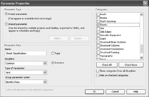
In the Parameter Properties dialog box (Figure 14.24), set the values as follows, and then click OK twice to close the dialog boxes:
Parameter Type: Project Parameter
Parameter Data | Name: Sheet Classification
Parameter Data | Discipline: Common
Parameter Data | Type of Parameter: Text
Parameter Data | Group Parameter Under: Identity Data
Parameter Data: Instance radio button
Categories: Sheets
In the Project Browser, click sheet A100 to highlight it.
In the Properties palette under the Identity Data section, you will see your newly created parameter called Sheet Classification. Enter Floor Plan as the value, and click OK (Figure 14.25).

Now that you've identified the view, you need to set the Project Browser to display that new level of organization.
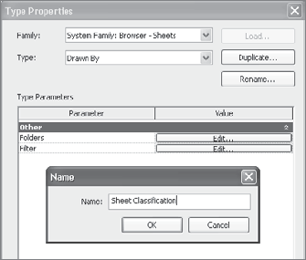
In the Project Browser, right-click Sheets (All), and select Type Properties.
In the Type Properties dialog box, change the Type (All) to Drawn By. You need to do that because you can't duplicate the All type.
Click Duplicate, and enter Sheets Classification (Figure 14.26).
Click the Edit button to the right of folders.
In the Browser Organization Properties dialog box, set the following:
Set Group By to Sheet Classification.
Set Then By to <None>.
Set Sort By to Sheet Number.
Select the Sort By: Ascending radio button (Figure 14.27).
Click OK twice.

Now all sheets are stored under the right Sheet Classification except for 3D views. Notice that all the sheets that do not have the Sheet Classification set yet are stored under ??? (Figure 14.28). Simply set the Sheet Classification value for the remaining sheets.

Before you move to printing, you will create a sheet list to place on the title page:
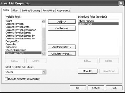
On the View tab's Create panel, click the Schedules drop-down button, and select Sheet List. This will open the Sheet List Properties dialog box.
In the Sheet List Properties dialog box under the Fields tab, add two fields to the Scheduled Fields list (Figure 14.29): Sheet Number and Sheet Name.
Under the Sorting/Grouping tab (Figure 14.30), do the following:
Set Sort By to Sheet Number.
Select Grand Total, and set it to Count And Totals.
Make sure Itemize Every Instance is selected.
Click OK to close the Sheet List Properties dialog box. The schedule now displays the list of the sheets sorted by number and shows a total of sheets.
Create a new sheet called Sheet A000 - Title Page.
Drag the schedule called Sheet List from Schedule/Quantities in the Project Browser into the drawing sheet (Figure 14.31).


Although Revit provides many great tools for modeling in 3D, in the end you are still creating 2D sheets to review, print, sign, and seal. In a perfect world, you could print sheets on paper and not have to worry about the cost or environmental issues related to using paper. To reduce waste and improve communications, Autodesk has provided the Design Web Format (DWF) file format. With DWF files, you can export 3D models and sheets in a lightweight file format that can be read and marked up in a free application. DWF files are a great way of communicating your designs to your clients or even other consultants. They are lightweight, easy to work with, and really reliable.
DWF files let you share design information securely and easily. Using the DWF format, you can avoid unintended changes to project files, and you can share project files with clients and others who do not have Revit Architecture. DWF files are significantly smaller than the original RVT files, making them easy to send by email or post to a website.
DWFx files contain the same information as a DWF file but can be opened and printed using the free Microsoft XPS viewer.
Note
To view a DWF, the other party will need DWF Viewer Design Review, which can be downloaded from the Autodesk website (www.autodesk.com).
A great use for DWF files is to review projects. They can be used to mark up the project without using a single sheet of paper. Once the files get marked up by a project manager, they can then be relinked into Revit for an easy workflow. Markups will appear exactly on top of the proper sheet. To create a DWF, follow these steps:
Choose the application menu, and select Export
The first step is to select what you want to print. Generally speaking, you will export sheets rather than views. Your sheets will contain all the relevant views. If you were to export sheets and views, each view that has been placed on a sheet would be a duplicate. Your building project also probably contains many views that are used to help construct your building project and that were never intended to be used in your construction documents.
In the DWF Export Settings – Views / Settings dialog box, on the View/Sheet Set tab, click the Export drop-down. Select <In Session View/Sheet Set>.
Under Show In List, select Sheets In The Model. This will display all the current sheets that have been created in the model.
You can click the Check All button to select all the sheets, or you can individually select them by simply selecting the Include check box for each required sheet. (Clicking a column header will allow you to sort the sheets using that header.) Click the Check All button.

The DWF Properties tab (Figure 14.33) allows you to manage the level of information that will be embedded into the DWF. Under Export Object Data, the Element Properties check box will allow the recipient to see the instance and type properties of the elements in the exported views. The Rooms And Areas In A Separate Boundary Layer check box exports the room and area properties to a layer separate from the geometry. This allows you to view individual rooms and room data when you are exporting a project or a view for use with facility management software.
The Graphic Settings option allows you to select which graphic format to use when exporting images. The Use Standard Format radio button exports images as PNG files; the Use Compressed Raster Format option exports images using a compressed JPG format.
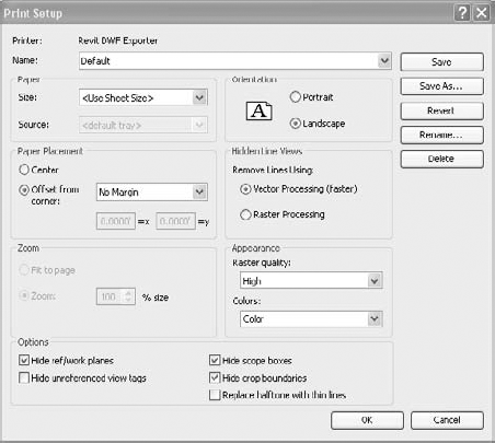
The Print Setup button allows you to control print settings. The print settings (Figure 14.34) are similar to those used by other Windows applications.

The Project Information tab allows you to make changes without having to go back to the project (Figure 14.35). This is handy if you need to adjust a check or issued date.
When you have made all the adjustments to the DWF Export Settings, click the Next button to continue the export. You will be prompted with the Export DWF dialog box (Figure 14.36).


Browse to a location and give the file a name. The default is the project name. The naming can be as follows:
- Automatic—long (specify prefix)
Manually specify a prefix in the File Name/Prefix field or accept the default, which uses this format: Revit Sheet/View: Project Name-View Type-View Name.
- Automatic—short
This format is Revit Sheet: Sheet Name or Revit View: View Type-View Name.
The Combine Selected Views And Sheets Into A Single Dwf File check box allows you to create either individual DWF files or a multisheet DWF file. If you have only one project manager review the set, then you can select the option. On the other hand, if you plan on having multiple reviewers, you're better off deselecting it so that all those people can access the files at the same time (which is impossible to do with only one file).
Note
You can also create sets to be able to easily retrieve sheets later. To do so, click the New Set button at the top left of the list of sheets, give the set a name, and follow the previous steps to complete your selection. Then click OK to save the set in the project.