
When working with multiple design alternatives, it can be frustrating to wait for a decision and then have to apply that decision to the progressing documentation. When using traditional CAD software, there are no specialized tools when you are dealing with design options. Fortunately, you get a purpose-built tool within the Revit platform called design options. With this toolset, you can start design alternative(s) at any time and apply the chosen design direction directly to the model—all views, tags, and schedules are coordinated instantly.
This chapter covers the following topics:
Design options terminology
Setting up design options
Editing design options
Applying design options to views and accepting the primary
Tags and annotation in design options
During the design process, you work on the design of a building with a particular outcome in mind and use the model to flesh out the ideas that everyone involved has for the building. At some point, you will need to explore (or be asked to create) alternative solutions to part of the building. It is at this point that design options become important. Before we go further, it is helpful to understand some of the terminology used in relation to design options:
- Main model
The main model encompasses the Revit model without any variations or alternatives. Before any design options are created, everything is part of the main model.
- Design option set
The option set is a collection of alternatives that address a particular design issue. A design option set uses a portion or area within the project where alternatives are being considered.
- Design option
A design option is one possible solution to the design issue. Each design option set will have at least one option. To be useful, you should have two or more showing alternatives. Each design option is specific to the issue addressed in the option set. You can have only one primary option (defined in a moment) per set.
- Dedicated view
You can dedicate a view to a specific design option for each design option set using the Design Options tab in the Visibility/Graphics dialog box. When this view is active or added to a sheet, the options you have dedicated are always shown along with the main model.
- Primary option
The primary option is the one favored by you or your client in the option set and shares a closer relationship to the main model than secondary options. Typically, the primary option is the one most likely to be accepted in the final design. Elements in the main model can reference elements in the primary option, and vice versa. By default, each view inside Revit is set to display both the main model and the primary option.
- Secondary option
The secondary option is another possible alternative to the primary option within the same option set. You can have one or more secondary option(s) within a design option set. Elements in the secondary option can reference elements in the main model; however, elements in the main model cannot reference elements in the secondary option.
- Automatic display
When design options are enabled, each view displays the main model and the primary option, if no options are being edited. By default, the visibility of a design option is set to automatic, which shows the primary option, and the visibility can be adjusted to show secondary options by going to the Visibility/Graphic Overrides dialog box. You can control the visibility of design options within the model for the following views: plan, elevation, 3D, and drafting. If you are editing an option, the view displays the main model and the option you are editing.
To be clear, we are not talking about wholesale design changes to the entire model (in other words, a design with a large circular footprint vs. a design with a large rectangular footprint). Completely different building design solutions are better represented in different Revit model files. Instead, we are talking about design options to parts/portions within the overall design. The following are some examples:
Alternative entry designs
Interior departmental plan layouts
Furniture design/layout
Exterior façades
Predefined, repeatable layout configurations
Quantify metrics/values with schedules
Roof configurations
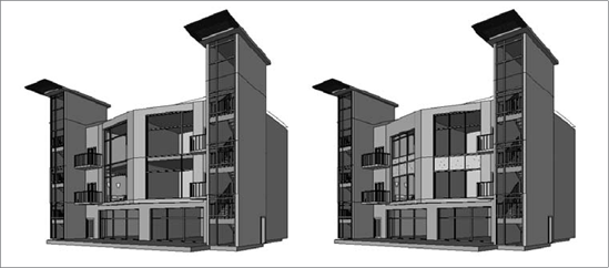
Figure 15.1 shows examples of two design options within the building's exterior curtain wall.
Note
In other CAD systems, having multiple design options means having multiple files or one file with multiple copies of the same geometry. A change to one does not mean the others change. Inconsistencies are inherent in this type of process, and errors are common. Revit addresses this issue by allowing you to develop and document multiple design options simultaneously as the rest of the design moves forward. Revit can synchronize these alternatives with the design once a decision has been made on which to keep and which should be removed, and the project can move forward without the need for manual intervention.
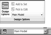
You can access the design options in one of two ways. You can select the Manage tab and click Design Options (see Figure 15.2), or, new in Revit 2011, you can click the Design Options button in the Status bar along the bottom of the screen.
When creating design options, you begin by defining an option set. An option set is a "grouping" of options. It is good practice to keep your option sets isolated to a specific task or area within the model. An option contains the model data/objects that show each alternative or competing design option/scheme.
To get you started, you will create two new option sets in this section. In the Option Set area, click New. In the Option area, click New and then New again to add a second option. Repeat these steps to create a second option set that contains two options (see Figure 15.3).
Within each area you can rename the options sets to something more descriptive. To do this, highlight the option set or option, and choose Rename from the appropriate section. In Figure 15.4, the Design Options dialog box shows the design options renamed with two option sets called First Floor and Main Entry East. Within each option set are multiple alternative design options of differing configurations. In the Main Entry East set, you will be exploring two schemes; Single Door w/ Sidelights is the primary option, and Double Door is a secondary option. You can have multiple options under each option set, but only one entry within each option set can be considered the primary, or top, choice until a decision has been made to eliminate the others.

Note
The default names of design option sets are Option Set 1, Option Set 2, and so on. You will find it easier to rename these from the start to something more descriptive. Unfortunately, you cannot simply select the option set from the "white area" of the dialog box. To rename, you will need to select your option set, click the Rename button in the Option Set section on the right, and rename it in the Rename box.


Click the Close button to edit the design option.
You will know that you are editing a design option in one of two ways:
The first way is graphically. In the plan, elevation, 3D, and drafting views, the existing geometry that is part of the main model will be displayed as ghosted.
In the Status bar, the white area will show the name of the design option that is being edited (see Figure 15.5).
At this point, you can go back to designing with standard Revit elements that best show the design option you are trying to convey. When this design option is at a point where you want to stop editing, you must open the Design Options dialog box and click Finish Editing. You can edit or make adjustments to a design option at any time by returning to the Design Options dialog box.

Note
If you are done editing a design option or just want to get back to working with the main model, you can choose Main Model from the Status bar's Design Options drop-down menu. This is the same as opening the full Design Options dialog box, clicking Finish Editing, and then clicking Close.
On the Status bar when a design option is being edited, you will notice a small Active Only check box (see Figure 15.6). When this is selected, any geometry within the main model is ignored while picking or windowing. With the Active Only box deselected, the main model will still be ghosted, and all the geometry within it can now be selected.
If you are in the main model, the Status bar's Design Options area will show an Exclude Options check box instead. This plays a similar role to Active Only except in reverse; within the main model with this selected, Revit will ignore any design options displayed from accidentally being selected. Deselecting this will allow you to select objects with a design option.

A common use in deselecting the Active Only check box and clicking the Add To Set button on the Status bar is when there are objects that you would like to copy from the main model to include in one or more design options. As an example, let's take a furniture layout that was originally done in the main model and now consider different layout configurations. The steps to set this up are as follows:
Create a new design option set.
Create as many design options as needed to show the different layouts.
Close the Design Options dialog box.
Select the furniture to move from the main model (making use of picking, windowing, and/or filters), and place it within one or more of the design options created earlier. To do this, with the objects selected, click the Design Options status bar's Add To Set button. In the Add To Design Option Set dialog box (see Figure 15.8), choose which design option set this should be part of and which design option (one or more) you want to move the selected objects into.
This step will remove the geometry from the main model and place it within one or more design options as selected.
If geometry already exists that you want to move into a design option set, take advantage of the features that Revit offers to pick, select, and filter, including the Exclude Options and Active Only check boxes on the Status bar. Use the Paste options on the Modify ribbon (such as Paste Aligned) as needed as well.

Now that you understand and have created design options sets and defined the design options, it is time you take this knowledge and show it graphically in different views. Once you've decided which design option you want to keep, you will merge this into the main model by accepting the primary.
You will be using the floor plan in this example. Keep in mind that the process for working with all views and showing the different design options is similar. Within the floor plan that you want to work with, you will visually see the main model as well as the primary design options by default. You will set up the views to show the other design options by first duplicating the view as many times as you need to match the number of design options you want to show.
In the Project Browser, select the floor plan that you want to work with, right-click, and choose Duplicate (to duplicate just the floor plan) or Duplicate With Detailing (to include a copy of the annotation). Take a moment to rename the view to help you better understand which design option this is going to relate to.
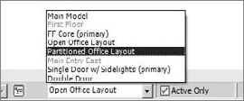
Next use the Visibility/Graphics (VG) to change each view from showing the Automatic value or Primary option and showing a specific design option. On the Design Options tab (see Figure 15.9), you will see each of your design option sets listed and a drop-down that allows you to select a particular design option.
Select the appropriate design option, and repeat the process for each option. This will then display the main model plus the selected option. Figure 15.10 shows two examples of the main model with different design options.
Repeating this process, you can create the required presentation drawings showing multiple design options, plans, schedules, and 3D views and place them on sheets for presentation.


Note
You can also use shade and shadows to better illustrate graphically the impact that the decision has on the project.
To tell schedules which design option to display, you cannot use the shortcut key VG; rather, open the properties, and on the Visibility/Graphics Overrides line under Graphics, click Edit (Figure 15.11). Then select the appropriate design option (Figure 15.12).


When you've decided which design options to proceed with, you should set that choice as the primary option. If it is currently a secondary option, you can elevate it to the primary option status in the Design Options dialog box. First select the design option, and then click Make Primary in the Option area (shown earlier in Figure 15.4). Once you've designated the desired choice for the project as the primary option, select the design option; the choice of Accept Primary will now be available. Clicking this will remove the objects within from the design option, place them within the main model, and coordinate them through the documentation set. The design option set and any design options within it will now be deleted (with a warning, shown in Figure 15.13).

Additionally, once you do this, you'll see an option to delete any now-unused views. This will help you keep a clean Project Browser. Repeat these steps as the project progresses for each design option set.
It is straightforward to add room tags after the design options are created. Although it does not always happen in that order, it does illustrate what Revit is ultimately looking for. So, in this section, you will start with the methodology that Revit prefers and then learn how to proceed when you already have rooms created when you create design options.
If the rooms are created before you introduce design options, keep these two tips in mind:
Be sure to use the Duplicate With Detailing option to create the views. That way, the room tags are already shown in each view.
When adding elements to the first option, be sure to select the room tags. That way, they (and the room boundaries) will not be part of the main model. If you miss one (or more), there will be some confusion when you create the second option. Otherwise, everything else works the same.
After design options are created, keep these things in mind regarding tags:
Make sure you are not editing any design option. Start with the view that shows your Design Option 1 and the main model. Add the first room tag to the plan (this is assuming that the first room is the same in both designs). Edit the room number to the desired number. This establishes a pattern for Revit to follow. Now proceed by tagging all the rooms that are the same in both design options.
Next, use the Edit Selected button for your first design option. Now add room tags to the rooms created by the walls in Design Option 1. At this point, you should have the plan tagged. Everything looks good. But this is where it gets tricky. End editing the first option, and return to the main model. Open the view for Design Option 2. Place a room tag in one of the rooms that is the same in both options. It should pick up the number you gave it in the Design Option 1 view. Because it is the same "room," it wasn't tagged. You can proceed to tag all the rooms that are the same in both options. If you accidentally tag a room that overlaps with a room in Design Option 1, you will get a warning. Don't panic. Just delete the tag you just placed. When you get the warning that says it can be ignored, don't ignore it!
When you're ready to tag the rooms formed by walls in Design Option 2, use the Edit Selected option, and add tags within the view. The same warning will show up if you attempt to tag a room that is not part of the design option (in other words, it is the same in both options). You will be able to renumber the tags in a design option to follow the numbering scheme of the main model.
So, when you think about it, it really makes sense. If you want to tag a room common to both design options, do it in the main model when not editing a design option. When you want to tag a room created by a design option, do it while editing that design option. This is what Revit is expecting.
Note
For the numbering of room tags, the last value used influences the pattern of the next values. For example, if you started with Room 101, the next room would be 102, and so on, unless you manually changed a value and then started the next room tag. This is useful when trying to match the numbering scheme of the main model. Also, when working with design options, you can have "duplicate" numbers provided they are not in the main model. Because the two design options cannot coexist in the same option, Revit does not see them as duplicated.
Here are some more considerations related to including rooms in options:
Rooms can be placed in each design option independently. The room bounding areas and room separation lines in that option, in the main model, and in primary options of other option sets define the boundary. Revit ignores walls and room separation lines in secondary options of other option sets.
To assign different room properties, such as occupancy, in different options, the room must be included in that option.
If the shape, size, or location of a room varies in different options of one option set, then the room must be included in that option set.
If the shape, size, or location of a room varies when you switch among different options of two or more option sets, then you must divide the room with room separation lines into rooms, each of which varies in only one option set, and then put each room into the appropriate option set.
If the shape, size, or location of the room is the same in different options and you want properties assigned to the room to be the same for all options, keep the room in the main model.
If you place a room in an area that already has a room assigned to it, you will get the following error: Option Conflict.
Tagging doors and windows is a bit different. The tags for these elements are visible and editable whether or not you are editing a design option. In other words, they are not part of any design option. This is why when you select objects and try to add them to a design option, if you have included door and window tags (and some other elements as well), you receive a warning.
Using annotation tools (such as Text, Detail Lines, Regions, Detail Groups, and Insulation), you can interact with the design options and views. While editing a design option, you can place an annotation, and although it may seem like you are adding this to the design option itself, Revit is actually placing this in the active view in the main model and not as part of the design option.
Dimensions behave like the previous annotation elements. Where they differ is that when the design option displayed within the view is changed, dimensions that are associated to geometry within that design option will no longer be displayed unless that design option is visible within the view.