
Continuing from the preceding chapter, you will now move on to modeling a very simple human base mesh in Maya and making slight modifications for it to be a female. Then you will create UVs for the model by using Headus UVLayout. After this point, you will have a simple human-form base mesh that you can easily pose. You will then pose the base mesh with the new posing toolset in Mudbox 2011. Finally, you will subdivide the model and sculpt it.
This chapter includes the following topics:
Modeling the base mesh in Maya
Laying out the UVs in UVLayout
Posing the base mesh
Sculpting the model
Sculpt using a vector displacement map
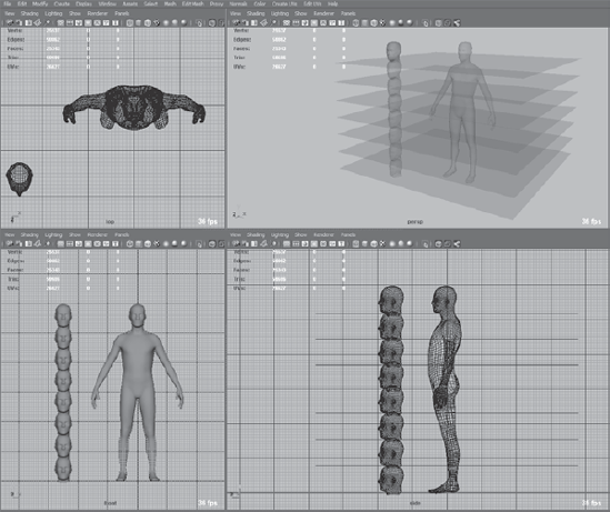
In this section, you will build a very simple human base mesh in Maya. You will start with a Cube primitive, extrude it, and use the Split Polygon, Insert Edge Loop, and Cut Faces tools to create the base mesh (Figure 6.1).
The reason you are not using the humanoid base mesh that comes in Mudbox is that, even though it is a good humanoid model for sculpting, it has a high polygon count that could prove more difficult to pose than the simpler mesh you will be modeling.
Maya is not the only application in which you can create a base mesh; any 3D application that enables you to do polygonal modeling and export your results as an .obj or .fbx file will also work. I have included a video, Chapter6-part1-Modeling_the_base_mesh_in_Maya.mov of me modeling the human base mesh on the DVD in the Chapter 6Videos folder. I have also provided a female and male version of the result of the work in this section as human_basemesh_male.obj and human_basemesh_female.obj files in the Chapter 61 - base_mesh folder on the DVD.
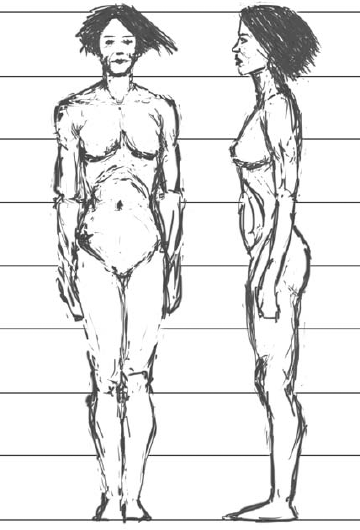
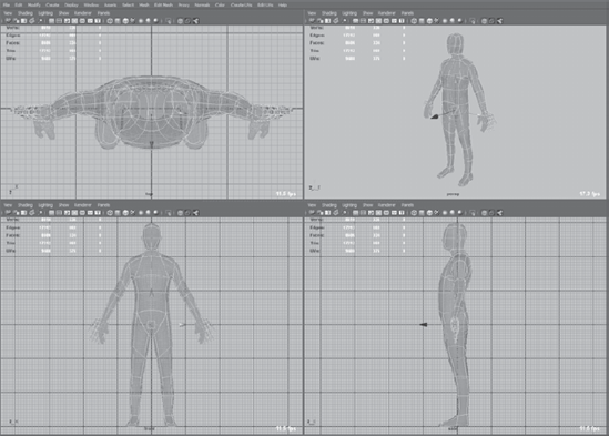
You will use the eight-head scale (Figure 6.2) to make this human base mesh. Note the eight-head scale intersection lines on the parts of the body. If you are familiar with drawing human anatomy, you should already be familiar with this; if not, there are plenty of great drawing and anatomy books that will give you measurement and scale guidelines to the human body. You could use image planes for the front and left viewports to model, but in this case, because you have a perfectly acceptable human mesh in Mudbox, you will use it as the guide to create the simple base mesh.
Follow these steps to create the base mesh:
Start Mudbox and load the Human Body primitive from the Welcome screen or click Create → Mesh → Human Body.
From the Select/Move Tools tray, select the Objects tool and then select the model.
Click File → Export Selection and export the model as
Mudbox_HumanBody.obj.Next you will set the grids in Maya to accommodate for the English measurement system, to show a grid line at every foot for a 6-foot-tall person. One foot is 30.48 centimeters, so if you are using Maya's default working units of centimeters, you will now have a grid line every foot that is divided by 12 subdivisions to indicate inches.
Start Maya and go to the options for the Grid by clicking on the options box to the right of Display → Grid menu selection. This brings up the Maya Grid Options dialog box.
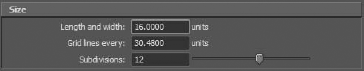
In the Size setting for the grid, type 16 in the Length and Width text box and type 30.48 in the Grid Lines Every text box. Finally, type 12 in the Subdivisions text box (Figure 6.3). Click Close to close the Grid Options dialog box.
You will now load the Mudbox Human body
.objfile into Maya and set it as a template.In Maya, click File → Import and select the
Mudbox_HumanBody.objfile that you exported from Mudbox.

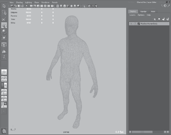
Click the middle square in the Layer Editor so it displays the letter T. This will set the objects in this layer, in this case, the human body, to be a template. Setting an object as a template makes it possible for you to see the objects, but you cannot select them. We are doing this because we are using this model as a reference. You might also want to click on the name of the layer and name the layer as something more useful (Figure 6.4).
Note that the model is about 6 feet tall. It is also eight heads tall (Figure 6.5).
Next, you will create a polygon cube and extrude some faces. Because the body is symmetrical along the y-axis, you will delete a symmetric half of the mesh, model half of the mesh, and then mirror it to the other side to get your final result.
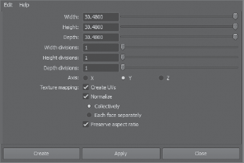
Click options box to the right of the Create → Polygon Primitives → Cube menu selection, and type 30.48 in the Width, Height, and Depth text boxes in the Polygon Cube options dialog box. Click the Create button for a 1-foot cube centered on the origin (Figure 6.6).

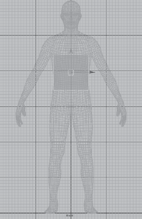
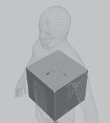
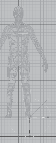
Use the green up arrow to drag your cube upward so that the top corners of the cube are aligned with the armpits of the model (Figure 6.7).
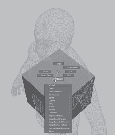
Press the spacebar and in the perspective viewport, right-click on the box and select Face from the marking menu (Figure 6.8). This enables you to select faces.
Rotate the model by pressing Alt and clicking and dragging the mouse in the perspective viewport so you see the top face of the cube. Then select the top face of the cube by clicking it with the left mouse button (Figure 6.9).
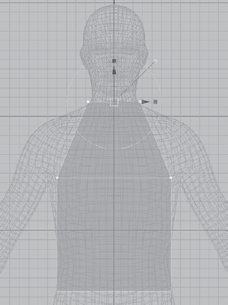
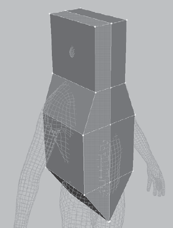
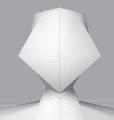
Make sure that the polygon menu set is active and that the drop-down menu in the top-left corner of the Maya toolbar reads Polygons. Press the spacebar, move your mouse cursor to the front viewport, and click the spacebar again. Click Edit Mesh → Extrude. Use the up arrow to extrude the cube upward, and the red square on the right to scale the extruded face in so it is approximately the width of a head (Figure 6.10).
Click Edit Mesh → Extrude to extrude another face to the top of the head (Figure 6.11).
Press the spacebar and in the perspective viewport, rotate the model by pressing Alt and clicking and dragging the mouse until you see the bottom face of the cube you started with. Then right-click on it with the left mouse button to select it.
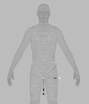
Press the spacebar, move your mouse cursor to the front viewport, and click the spacebar again. Click Edit Mesh → Extrude. Use the blue arrow to extrude the face downward, and the green square on the right to scale the extruded face in so that it is the length of the gap between the legs (Figure 6.12).
Click Edit Mesh → Insert Edge Loop Tool, and then click anywhere in the middle area of the model to create a vertical edge loop.
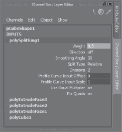
In the Channel Box, click PolySplitRing1 and type in a weight of 0.5 (Figure 6.13). This makes the edge loop you created move to the middle of the model.
Press the spacebar and in the perspective viewport, right-click on the model and choose Face from the marking menu. Select the left face on the initial cube you created, and then hold down the Shift key and double-click in the face above the one you have selected. This selects an edge ring (Figure 6.14).
Double-click on the remaining faces and press the Delete key again (Figure 6.15).
Press the Delete key to remove the selected edges. You now have half the model, which will be easier to work on, and when you are finished, you can mirror your work. Another reasonthat this is a good way to model is that it ensures that the model is topologically symmetrical, which as you saw in the previous chapter, is how you can still mirror-sculpt on a model that is not posed symmetrically.
Rotate your model, select the face for the leg, and click Edit Mesh → Extrudeto extrude out the leg. Click the circle handle attached to the extrude manipulator to switch fromlocal to world axes. Switch back to the front viewport, click the green arrow, and pull down the leg. Use the red arrow, the red square, and the rotate manipulators to move, scale, and rotate yourextruded face so that your newly created leg overlaps with the leg of the reference human (Figure 6.16).
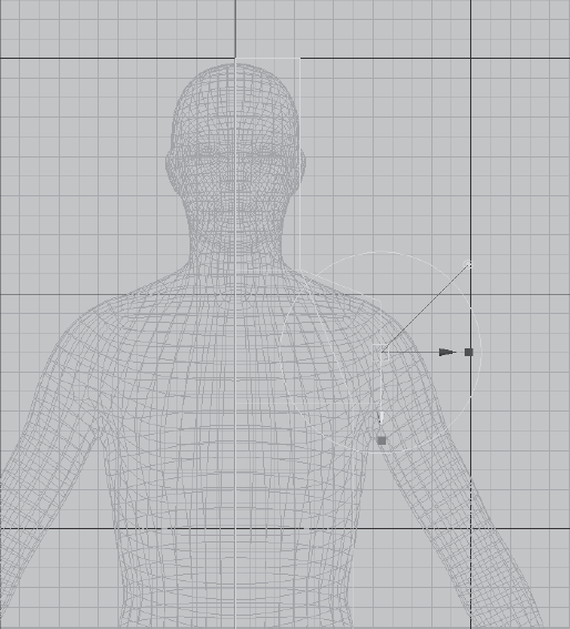
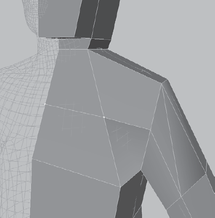
Select the shoulder face and click Edit Mesh → Extrude to extrude out. Use the Move, Scale, Rotate controls to extrude out the shoulder (Figure 6.17).
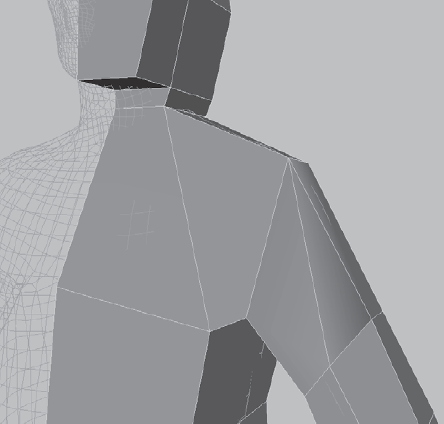
With the shoulder face still selected from the preceding step, click Edit Mesh → Extrude to extrude out the arm. Use the Move, Scale, and Rotate controls to extrude out the arm to about where the wrist would be on the reference figure (Figure 6.18).
Now you will use the Cut Faces tool to add more geometry to the model. The Cut Faces tool draws a line in the view window to define the cutting plane, which will draw edges on the selected face where the cutting plane intersects. You will start with the arm and use the Cut Faces tool to create an edge loop that will be the elbow.
In the front viewport, click and drag a rectangle on the arm to highlight the entire face of the arm. Click Edit Mesh → Cut Faces Tool. Notice that your cursor changes shape and you see the message Click-Drag to Cut. Click the location where the elbow would be and drag your mouse until you get an angle that best represents the pivoting of the elbow. Do the same to create two more cuts on the arm to divide the upper and lower arm (Figure 6.19).
Press the Q key, select the entire face of the leg, and use the Cut Faces tool to do the same thing for the leg that you did in the previous step. In addition to the two cuts to separate out the upper leg and the lower leg, add a third cut to mark a line where the top of the foot would be (Figure 6.20).
Finally, add two edge loops on the head—one at eye level, and another at the top of the neck. Then add another edge loop on the torso to divide it in half (Figure 6.21). Remember to press the Q key to select the faces before using the Cut Faces tool. You can hold the Shift key down before you let go of the mouse button to restrict your cutting line to 45-degree increments. This comes in handy to draw perfectly horizontal cutting planes.
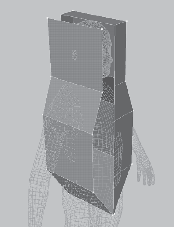
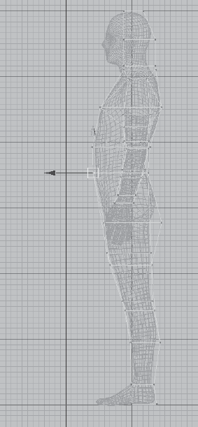
Go to the side viewport. Right-click on the model to bring up the markup menu, and then select Vertex to get into vertex selection mode. Select and move the vertices by using the drag rectangle mode to make sure that the inner vertices are also selected. Align all the vertices to a loose outline of the reference figure. If you have trouble determining which vertex belongs to the arm, you can either toggle between different viewports or work in the four-viewport mode, going back and forth between viewports. Note that you are just aligning the side outline at this time; you will do the rest later. Your end result should look like Figure 6.22. Note that the face and the foot are not outlined because you are going to extrude them.
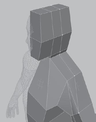
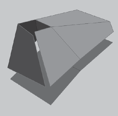
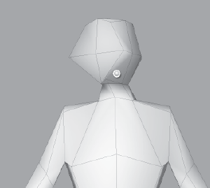
Under the Edit Mesh menu, make sure that there is a checkmark next to Keep Faces Together. In the side viewport, right-click on the model to bring up the markup menu, and select Face to get into face selection manipulation mode. Select the two front-facing faces of the head and click Edit Mesh → Extrude to extrude out the faces to the front (Figure 6.23). Use the same method of vertex manipulation as you did in the preceding step to align the newly created vertices. Note that the extruded faces also create a couple of faces on the inside of the model, which you need to select and delete.
Use the same method of vertex manipulation as you did in step 27 to align the vertices in the front viewport (Figure 6.24). Make sure you don't select any of the vertices on the y-axis because that is the axis you are going to use to mirror the model.
At this point you will add an edge loop to the arms to create some geometry to model the hands. Click Edit Mesh → Insert Edge Loop Tool. Click on the shoulder line and drag your mouse so it evenly divides the shoulder line (Figure 6.25). The progress so far is available for you on the DVD as
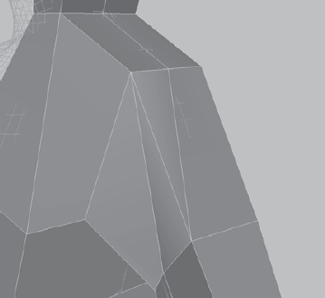
human_base_mesh - step 30.main theChapter61- base_meshfolder.With the new edge loop, you need to slightly modify the topology to add some more geometry to the head and to accommodate the flow of the arm. Click Edit Mesh → Split Polygon Tool and draw the edge connecting the upper-mid arm to the shoulder (Figure 6.26).
Select the edge indicated in Figure 6.27. Ctrl+click it and use the marking menu to select Edge Loop Utilities in the right corner. From the marking menu that comes up, select To Edge Loop and Delete (Figure 6.28).
Click Edit Mesh → Split Polygon Tool to connect edges as displayed in Figure 6.29.
Select the edge in Figure 6.30 and press Delete on your keyboard to delete it.
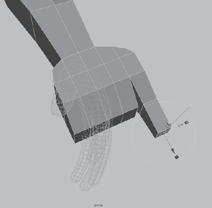
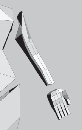
Finally, you will use Edit Mesh → Extrude to add the hands. Note that you will not model the hands to match those of the reference model. You will make the hands with the palms facing forward, and then you can modify the pose to easily accommodate the twist in the forearm with the posing tools later. In the perspective view, select the two faces of the bottom of the arm, extrude them out to about where the thumb begins, and then extrude again until you get to the knuckles (Figure 6.31).
Select the two outer faces and extrude out twice so that your second extrusion is at about the base of the thumb of the reference model (Figure 6.32). Do the same on the other side, but just extrude out once.
In the front viewport, adjust the vertices of the base of the hand the same way as in Figure 6.33.
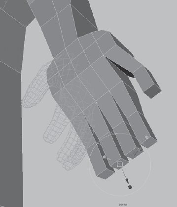
Extrude the four inner fingers out to about where the knuckles of the reference model are. Use the yellow cubes to scale them in a bit and then use the green arrow to translate them back (Figure 6.34).
Extrude the thumb out once, scale and translate the extruded face, and extrude it a second time to match the shape of a thumb (Figure 6.35).
Click Edit Mesh and deselect Keep Faces Together. In the perspective viewport, select the faces that would make the four fingers and extrude them out, use the red and green cubes to scale them in a bit, and extrude them again a second time (Figure 6.36). At this juncture, you could extrude them out one more time to create the three joints of a finger, but you have enough geometry for the pose you need.
Select your model, and then right-click to select Object Mode from the marking menu. Click Mesh → Mirror Geometry to bring up the Mirror Options dialog box. You will want to mirror our model in the negative X direction, and you want to make sure that Merge with the Original and Merge Vertices are selected. Click the Mirror button in the Mirror Options dialog box to create a mirror of your model (Figure 6.37). The progress thus far is available for you on the DVD as
human_base_mesh - step 41.main theChapter61 - base_meshfolder.

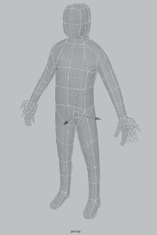
Right-click on the model and choose Vertex from the marking menu. Start moving the vertices to get a shape that is as close as possible to the reference model. Remember, the hands do not need to change in pose; you just need to make sure the proportions look correct (Figure 6.39). Note that as you modify the vertices, the modification is reflected to the other side because Reflection is turned on in the Move Tool options.
Press 1 and notice that as you get back to the unsmoothed version of the polygon, it looks very odd, but this base mesh will produce a base mesh similar to the reference model when you subdivide it in Mudbox. The progress thus far is available for you on the DVD as
human_base_mesh - step 44.main theChapter61 - base_meshfolder.Make sure you have the
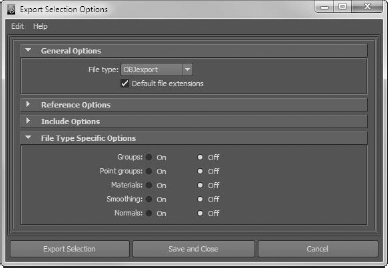
objExport.mll(or bundle on the Mac) plug-in loaded by clicking Window → Settings/Preferences → Plug-in Manager and checking to make sure the Loaded check box is selected forobjExport.mll(or bundle on the Mac). Right-click on your model in the perspective view, choose Object Mode, and select your model. Select the options for File → Export Selection, choose OBJexport from the File Type drop-down list, and scroll to the end and make sure that all the File Type Specific Options are turned off (Figure 6.40). Click Export Selection and save your base mesh ashuman_base_mesh_male.obj.One last thing to do, because our intended sculpt is that of a female, is to make a female version of this base mesh. This is very easy and requires making only minor adjustments. First, you need to note that the general anatomical differences in the two sexes at the detail level of the body we have are as follows:
Lower and larger pelvis as the center of gravity of the female body
Narrower shoulders
Longer neck
Smaller hands and feet
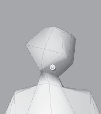
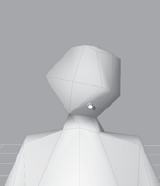
Smaller, rounder head
Women generally also have larger cheekbones, a softer jaw line, a less-pronounced chin, and a larger space between the eyebrow and upper eyelid, but don't worry about that at this juncture.
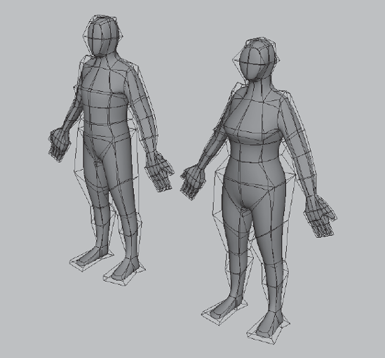
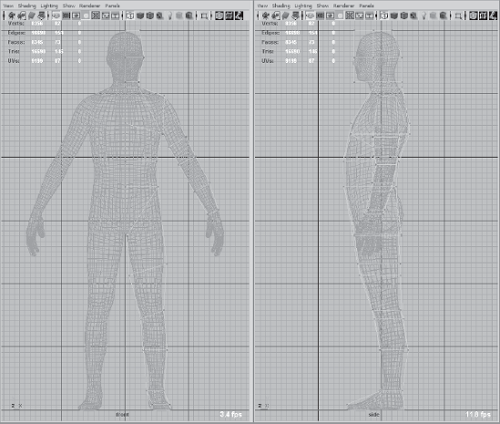
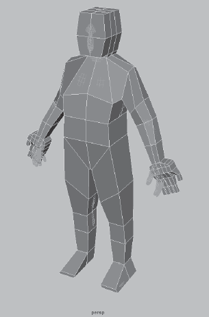
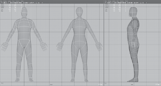
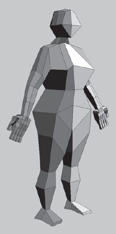
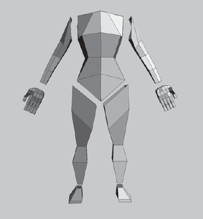
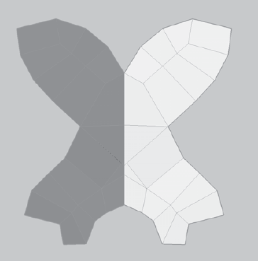
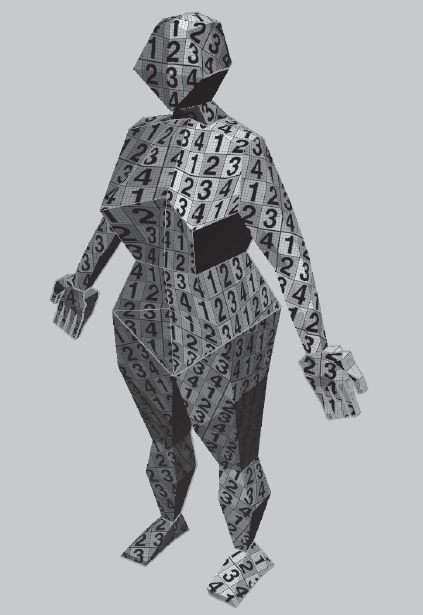
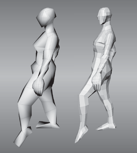
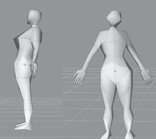
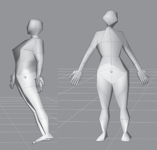
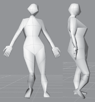
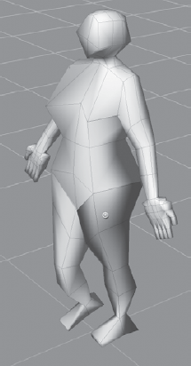
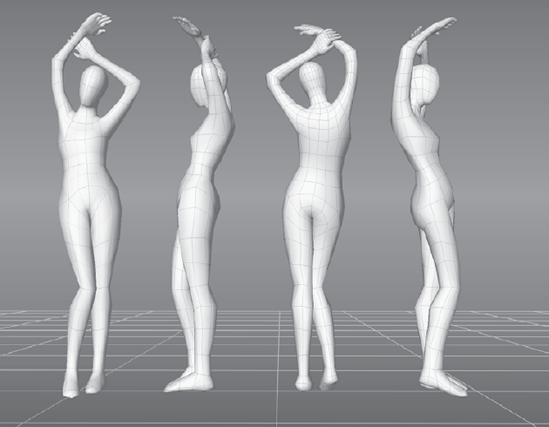
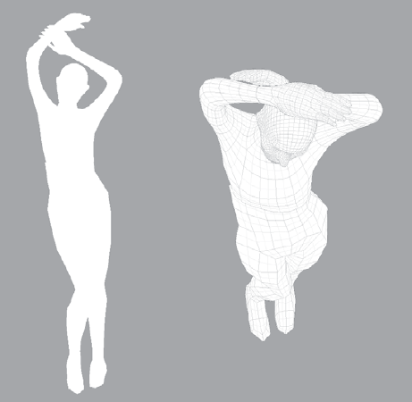
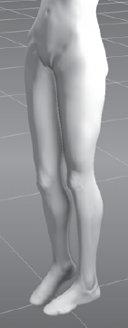
Adjust the pixels on your model to account for the five differences listed. Notice that even at this low level of detail, you can tell the difference between the two sexes from the simple silhouettes (Figure 6.41).
Export the female version of your base mesh and call it
human_base_mesh_female.obj.


The progress thus far is available for you on the DVD as human_base_mesh - step 46.ma in the Chapter61 - base_mesh folder.
You are finished with creating our very simple yet effective human base meshes that you can use to sculpt on. However, you still need to lay out the UVs of this model, which is what you will do in the next section.
I have found Headus UVLayout to be the easiest and fastest way to create UVs for our model. You can use it as a stand-alone application or interact with it through plug-ins or scripts that are available for the most popular 3D applications. You can download a trial version of the software from www.uvlayout.com, and it is available for sale in different configurations for different customer needs. I have found the pro version to be well worth its asking price because of the amount of time and aggravation it saves you. The website also has plenty of great videos to teach you how to use the software in addition to showing off the amazing feats this software can perform. The camera navigation in UVLayout is the same as it is in Maya and Mudbox. I have included a video, Chapter6-part2-UVLayout.mov on the DVD in the Chapter 6Videos folder, of my laying out the UVs of the base mesh in UVLayout.
The steps you will go through to create UVs are the following:
Load the
human_base_mesh_female.objfile.Find good places for seams to cut to separate the mesh.
Flatten the pieces into UV shells and pack them in 0 to 1 UV space.
Export out the
.objfile with the new UVs.
One thing to note is that I will not discuss UVLayout in depth, but will go through only what you need to do to create the UVs for this base mesh so you know where to start to create UVs for the base meshes you make for various projects. If you are comfortable laying out UVs in Maya or your preferred 3D application, please do so and skip this section. I have also provided finished versions of the model with UVs laid out for you on the DVD so you can just read this portion and then load the .obj file with the UVs into Mudbox for the next stage.
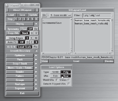
Start UVLayout, click Load, and navigate to where you saved your
human_base_mesh_female.objfile and open it, or load the one from theChapter61 - base_meshfolder. Make sure that New is selected, which tells Headus to disregard any UVs that the model has because you will be creating new ones (Figure 6.42).Headus will load this model into its Ed view or UV view. You can cycle between the three views (UV view, Ed view, and 3D view) by pressing the 1, 2, and 3 keys, respectively, on your keyboard. You will use the Ed view when you cut the seams and separate out the various shells.
Again you can use symmetry and do half the work. Press 2 to be in Ed view. Click the blue Find button next to the word Symmetry, click on an edge that is in the middle of the model, and press the spacebar. This colors half your model a darker shade of gray to indicate that symmetry is on (Figure 6.43).
The head is always a good place to start. Move your cursor to any edge on the neckline and press the C key. This will mark that edge for cutting and it will also select its edge loop in yellow. Press Enter to perform the cut and separate the head (Figure 6.44).
Cut a seam from the tip of the forehead to the base of the back of the neck. Cut another horizontal seam across the back of the head. If you cut seams that you didn't mean to, move your cursor onto the edge you intend to weld and press the W key. Press Shift+S to separate the cut seams (Figure 6.45). Place your pointer on the head and press the D key to drop it into UV view. Press 1 to see the dropped head in UV view.
Cut seams around the wrists, legs, and arms, as in Figure 6.46. While pressing the spacebar, you can click and drag the pieces to move them.
Cut a seam in the back of the arm and press Shift+S to open up the seam (Figure 6.47). Move the cursor onto any one of the two arms and press the D key to drop both arms into UV view. Press 1 to see both arms and the head in UV view, and then press 2 again to return to Ed view.
Cut a seam along the inside back edges of the leg, and press Shift+S to open up the seam. Move the cursor onto any one of the two legs and press the D key to drop both of the legs into UV view.
Cut a seam in the torso in the back (Figure 6.48). This might prove a little difficult because there are intersecting planes in the model. Take your time and rotate around the model to find the seams and then press the C key to cut them. You can also go to the Display menu and move the X-Ray slider to the left to make the model a little more transparent so you can see the intersection lines better. If you make accidental cuts, move your cursor to the edges you accidentally marked for cutting, and press the W key. Move your mouse cursor on top of the cut piece and press Enter to separate that piece out. Note that there are three areas that need to be separated. The first seam is from the neckline to the top of the shoulders, the second area is the sides, and the third is the bottom rear. When you are finished cutting and the pieces separate, move your cursor onto the cut pieces and press the D key to drop them into UV view.
Cut a seam around the soles of the feet and press Enter. Then cut a seam on the inside of the ankle and press Shift+S to open up the seam (Figure 6.49). Move your cursor onto the cut pieces and press the D key to drop them into UV view. At any point, if you want to frame whatever pieces are left in Ed view, press the Home key and it will show all the components that have not been dropped into Ed view.
The only two items left are the hands, and you need to cut seams in only one hand because the mirroring actions will repeat on the opposite side. Cut seams on the top and bottom of the hands (Figure 6.50), dividing each hand into three shells. Move your cursor onto each of the pieces and press the D key to drop them into UV view.
You are finished cutting the seams and have all the shells ready to be flattened. Because of symmetry, you need to flatten only one side of the model and copy the work over to the other.
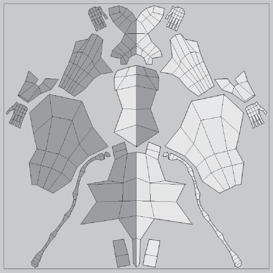
Press 1 to go to UV view; notice that all your shells are arranged at the bottom of the view (Figure 6.51) and they look as though they are still in the shape they were when you dropped them into UV view.
You can work on the shells anywhere on the screen. Don't worry about the arrangement just yet; you will arrange them when you are finished flattening all the shells. Click on the shell for the head to select it, press the spacebar, and click and drag with your middle mouse button to move it to an empty space in UV view.
With your mouse cursor on the head, press the F key to flatten it a little. You can also press the spacebar and the F key to continuously flatten until you press the spacebar againto stop. Or, you can just press Shift+F to activate the Bloat Then Reflatten function and watch as the head first gets stretched out and then flattened to completely unfold. This process alone is why using software such as UVLayout will cut hours of drudgery out of UVing.
The Bloat Then Reflatten function does a decent job of flattening the head. Headus UVLayout uses a color code to identify ideal, stretched, and compressed faces. Yellow indicates an ideal face, red is stretched, and blue is compressed. The shades of the aforementioned colors indicate howstretched or compressed the faces are. Solid blue or red is undesired. Solid yellow and the lightest possible shades of red and blue are what you strive for. As you see on the flattened head UV, there is a hint of a darker red in the bottom half of the face. Because this is an important area that will be painted and sculpted, you want to make sure you get them to be green.
Press Ctrl and middle-mouse click and drag on the vertices of the face to move them in a direction causing the face color to turn yellower. Remember, you need to do this only on the lighter side of the face. Move the vertices slightly until you have a shade close to the lightest shade of yellow, and when you are finished, move your mouse cursor on top of the half of the face that you worked on and press the S key. Notice that the S key mirrors the contents of the lighter mirrored area to the darker one (Figure 6.52).
Press 3 to go the 3D view. Press the T key to place a checkered pattern on the face. Press the T key again to get a more granular display with a grid and numbers. Tumble your model around the head and observe the effects of wrapping a texture on your model with all the stretching and compressing visible. You can also see the underlying shades of green, red, and blue, especially if you have solid blue or red areas. Going back and forth pressing 1 and 3, repeat step 14 until you are satisfied with the results (Figure 6.53). The pattern might look a bit skewed. but that is due to the very little geometry you are working with. As this model subdivides, you can reload it into UVLayout and do further refining.
Repeat the process performed in step 15 on all the other pieces of the model until you have the model completely flattened out. Remember to press the S key to mirror your work to the other side. Most of the pieces will flatten out pretty easily. The chest might need some extra work, but because you have very little geometry, the task is fairly simple and quick. When you are finished, you will have all the shells flattened all over the UV screen and you can press 3 to see the pattern all over your model (Figure 6.54).
The next step is to pack all the pieces together. You can click on the individual pieces and use spacebar+left-click and drag to rotate them. Pressing the S key while clicking on the pieces mirrors them and also has the added benefit of placing them next to your piece. You can either manually arrange the pieces in the first UV tile or let the software do it for you. To manually move the shells, click on the shells to select them and then hold down the spacebar and middle-click and drag on the shells; they will turn pink, and you will be able to position them anywhere on the screen. You can also resize the shells by using the spacebar+right-click and drag combination, but this is not something you need at this juncture. To have UVLayout arrange the shells foryou, click the Pack button, which will expand the packing options for you. Select Best, because you have only a few shells and the time taken will be nominal. You might want to revisit this with Fast or Mid in the future for models that have more polygons if UVLayout is taking too long to arrange your shells. Type 6 in the Bleed textbox to make room for 6 pixels between the UV shells and the borders of the 0 to 1 UV tile. Click Pack All and watch UVLayout arrange your pieces for you (Figure 6.55).
I find that I need to do a bit of arranging myself to get a little more space efficiency and proximity of shells to patterns (Figure 6.56).
I have included the files
pre_drop.uvlandfinal.uvlon the DVD in theChapter 62 - UVfolder. You can load these into UVLayout to catch up to the progress or see my work.Finally, you will save the model as
human_base_mesh_female_UV.obj. I have included my version of this model as well, on the DVD in theChapter 62 - UVfolder.


I hope you have seen how UVLayout can simplify the process with its amazing capabilities of Symmetry, Bloat and Reflatten, and the automatic packing of the UVs. There are plenty of other extremely useful capabilities that I did not have the time to get into, so make sure to look at the videos on the website.
You now have a model with UVs ready to import into Mudbox for posing and sculpting.

A good pose makes or breaks your model's presentation. It's always ideal to have a live model in front of you as a reference to sculpt the pose. If that's not available to you, 2D reference images work, but you need a good understanding of anatomy to figure out the weight distribution and balance of the angles beyond what is on your image. Having images from different angles helps but if you do not, you might want to consider either doing the pose yourself or coercing a friend.
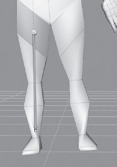
You should pay attention to balance so the pose looks plausible. Make sure you know where the plumb line and the center of gravity are on the posed figure. Do the pose yourself to get an idea of balance and weight distribution because that will help you with the balancing of your model. Think of the weight of the various masses of the body and how they influence the strain on the muscles. Ask yourself, If your model was printed as a solid, would it stand or fall over?
When posing a model, I always start with the three defining shapes of the body: the head, ribcage, and pelvis. Posing these three correctly makes the rest of the work easier, and if these shapes are not posed correctly, your entire pose will look unrealistic. The order in which these shapes are posed is up to you. Some people like to start with the pelvis, otherswith the head, and yet others with the biggest shape, the ribcage. So take your time in posing these three shapes, and the extremities will fall into place.
Finally, make sure to focus on the model's gesture. Make sure you have rhythm lines in the pose for your audience's eyes to follow. Study some of the classics; try to emulate some of the same poses yourself with your models. You might get a whole new level of appreciation for them.
With the introduction of the posing toolset in Mudbox 2011, you can now pose, position, transform, and scale your models into various stances without exporting your model to other applications. This capability removes yet another noncreative step from your workflow. Although the posing toolset is primarily aimed at posing characters, this capability can also be used to deform, move, bend, and twist noncharacter models. The four tools of the posing toolset are Create Joint, Pose, Weights, and Move Pivot. These are found in the Pose Tools tray.
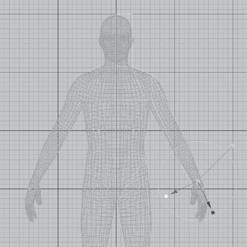
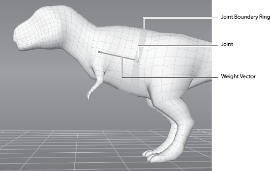
You can pose your model by using the Create Joint tool to place pivot points called joints on your model. These joints act as origins for translating, rotating, and scaling sets of vertices. After you place your joint on the model, you indicate which vertices it manipulates by drawing out a weight vector in the direction of the parts of the model you wish to manipulate (Figure 6.57).
Note
The color of the weights, which is green by default, can be customized by clicking Windows → Preferences → Color (Mudbox → Preferences → Color on the Mac) and adjusting the Joint Weight color.
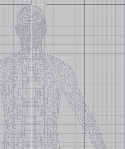
The region of influence is indicated in saturation levels of green; solid green areas will be influenced the most during posing (Figure 6.58), and the rest of the green areas will be influenced by their degree of saturation.
The region of influence surrounding the joint fades based on the Falloff curve property, which is the only property for the Create Joint tool. This falloff curve can be adjusted the same wayas adjusting it for sculpting or painting tools. The falloff determines how the weight changes between the area that is fully weighted (green) and the area that is completely not weighted (not green). Between those two extremes, the weighting can change linearly, exponentially, or however you specify based on the curvature of the falloff curve before creating the joint. You will see the results of this as the green coloration feathers off gently or with a sharper edge.
You can subsequently move the joint to a more suitable position by using the Move Joint Pivot, and also by adjusting the degree of influence, referred to as the weight, by painting it on in green or erasing it with the Weights tool. The Weights tool is identical to a paint tool in its usage.
Then you are ready to use the Pose tool to rotate, translate, and scale the weighted areas associated with the joint. The transformations of your pose use the camera view as a plane of reference. Clicking and dragging left and then right by using the left mouse/stylus button rotates the component about a vertical axis through the joint and planar to the current camera view (Figure 6.59). You do not need to click on the model; clicking anywhere on the screen works.
If you click and drag on the joint itself while pressing the left mouse/stylus button, a forward or backward motion rotates the component about a horizontal axis through the joint and on the same plane as the current camera view (Figure 6.60).
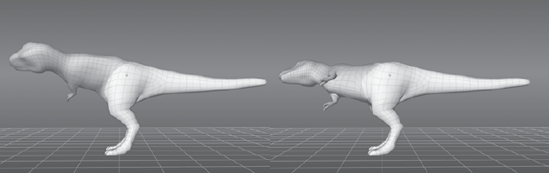
Figure 6.60. Rotating the area of influence by clicking and dragging on the pivot and moving the mouse forward or backward
If you click and drag on the pivot itself while pressing the left mouse/stylus button, a left or right motion rotates the component about a vertical axis through the joint and on the same plane as the current camera view (Figure 6.61).
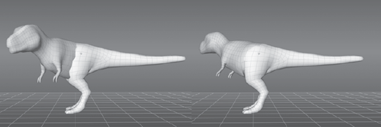
Figure 6.61. Rotating the area of influence by clicking and dragging on the pivot and moving the mouse left or right
To move the area of influence, click and drag on the region of influence with the middle mouse button (Figure 6.62). Notice that the geometry is stretched when you do this. You need to use the Smooth tool afterward to evenly distribute or relax the polygons. You might also want to export out the model and add a few more edge loops to the stretched-out area.
To scale the area of influence, click and drag on it while pressing both the left and middle buttons on your mouse or stylus (Figure 6.63). Notice also that the geometry is stretched in or out and is not in the same scale as the rest of the model.
You can invert the parts of the model that are to be posed by the region of influence when using the Pose tool by pressing the Ctrl key before clicking and dragging with any button to perform the rotate, move, or scale operation on an inverse selection of the area of influence (Figure 6.64).
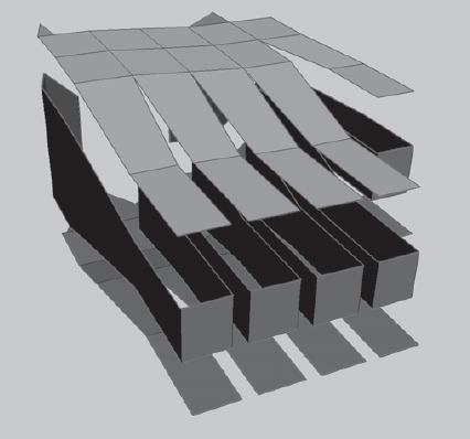
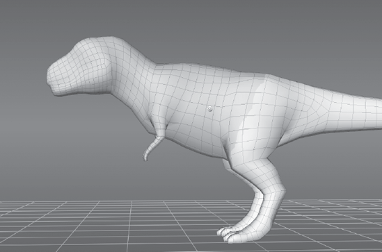
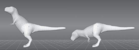
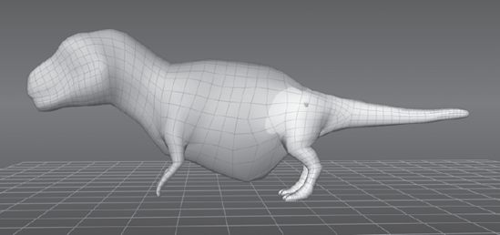
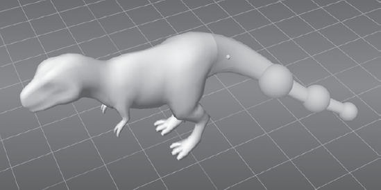
One of the most powerful capabilities of the posing toolset is posing multiple objects at the same time. This capability is extremely useful when you are posing a head with eyeballs as two separate objects, or a human figure with multiple clothing or accessory objects that need to be posed along with the body. The method for doing this is simple: You paint weights on the separate objects you need to move as well as on the part of the object that you are posing. For example, suppose we have the dinosaur in Figure 6.65 and a scenario where his tail has skewered three balls. If we pose the tail, we would need to move and position each of the three balls to accommodate for the pose, and if subsequent poses needed to be done to the tail again, we would have to repeat moving and positioning the three balls every time. With the posing toolset in Mudbox 2011, this process is made much easier.
After you draw the weight vector on the tail, which highlights the areas you will be able to pose in green, you can use the Weights tool to paint the three balls so they are within the influence of the tail pose. Choose a larger Size for the Weights tool than the size of the balls to paint the weights on faster.
Follow these steps to pose multiple objects:
Start Mudbox and load the
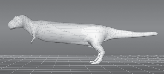
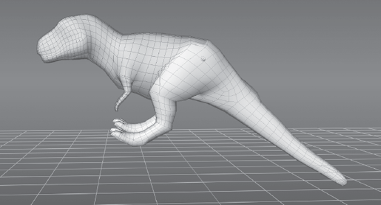
multi object pose.mudfile from the Chapter 6 folder of the DVD. In the Object List, notice that there are four independent meshes in the scene: the T. rex and the three spheres.From the Pose Tools tray, select the Create Joint tool and draw a weight vector on the tail (see Figure 6.65 earlier).
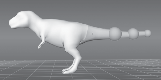
From the Pose Tools tray, click the Pose tool and pose the tail; notice that the three spheres do not move with the tail (Figure 6.66).
Press Ctrl+Z to undo the pose so the tail is in its original position, or reload the file and add the joint by repeating steps 1 and 2.
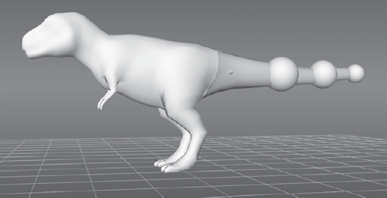
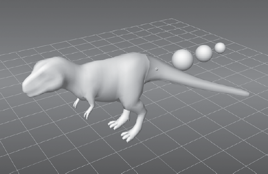
Click the Weights tool and choose a brush size larger than the spheres. Then paint weights on the spheres so they are completely covered in green (Figure 6.67).
Use the Pose tool to pose the tail; note that the three spheres now move with the tail (Figure 6.68).
Mesh objects get weight-painted individually, so if you click on a mesh, such as one of the spheres, you can continue to paint weights on the object, and only that object until you release the click, even if you move your brush onto other objects. This is also true when 3D painting. When you start a stroke on a mesh, you will paint only on that mesh, whether using the paint tools or the Weights painting tool, until you release the stroke. This makes it inconvenient to paint across multiple meshes, but extremely convenient if you intend to limit your work to one mesh.
An important thing to remember when posing is that Mudbox is primarily a sculpting program, so even though you have the new powerful and versatile posing toolset, your main posing tools are still the sculpting tools, primarily the Grab tool to move geometry around, and the Smooth tool to evenly redistribute the polygons after you move them around. Your workflow will be faster if you mostly use the Grab tool on the pose until you run into a limitation, such as rotation, that it can't address, or until you determine that your workflow would be faster if you were to use the pose tools for the specific scenario. The reason for this is that you can continuously use the Grab tool and adjust your model versus creating a joint, moving the joint, painting weights on the joint, and then posing it. That said, the Grab tool cannot do the work of the posing toolset, because some poses would be impossible to do with the Grab tool. It will take some practice working with the posing toolset and the sculpting tools for you to determine your best workflow for getting the perfect pose.
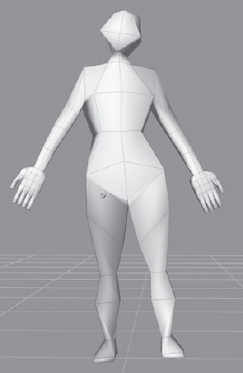
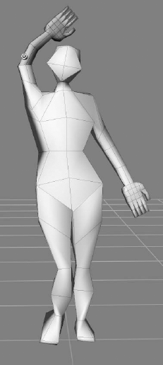
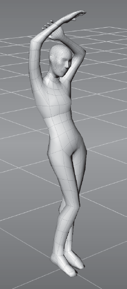
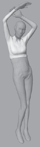
It is also best to pose your model at the lowest subdivision level possible because you then manipulate fewer vertices and polygons with the Grab tool or the posing toolset, allowing your workflow to progress much faster. This is the reason you modeled a human base mesh with the minimal geometry in Maya previously in this chapter. The model is easier to pose at this lowest subdivision level than at higher subdivision levels, and you can always drop down to the lower subdivision level and make the adjustments further on in the progress. You should be able to get your pose with the blocky view of the low-res mesh. In Figure 6.69, you can see the pose with the minimal geography. After the base pose is set, you can then move up in subdivision levels to do more fine-tuning of the pose and sculpt details.
In this section, you will pose the human base mesh you modeled earlier in Maya; you will start with the head, then the chest/ribcage and pelvis, and finally the arms and legs. I will be using references that I have collected over the years to create a collage of poses from various images. You can do the same, or try to do a pose of a classic sculpture such as Michelangelo's or Donatello's David, or any sculpture by Rodin or Degas.
I will go through posing the head, pelvis, legs, and an arm, and the methods used to pose them are the same for the rest of the model. Go through and pose the model yourself. You can load the fully posed model Pose_4_body.mud from the Chapter 63-pose folder of the DVD and examine the pose of the model I worked on. A couple of things before you get started:
Pose your model subtly and incrementally instead of making huge pose gestures. This will help you adjust the topology and polygon distribution as you go along versus major changes in a pose that might need much more work to adjust.
Place each pose on a separate sculpt layer so that you can easily undo it by deleting the layer or adjusting the opacity of the layer to fine-tune your pose.
Even though you have a very low-polygon-count model with the base mesh, you can define the gesture of the model here with the pose:
Either load the model you created the UVs for in the previous section, or load the
human_base_mesh_female_UV.objmodel from theChapter 62 - UVfolder of the DVD.Create seven sculpt layers called
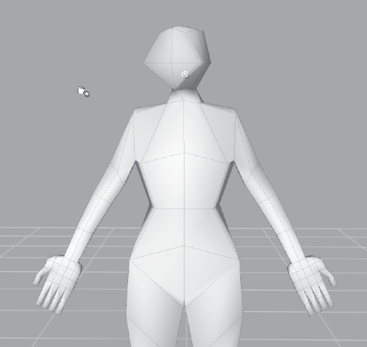
head, ribcage, arm_lf, arm_rt, pelvis, leg_lf, leg_rt. Save your model aspose_1.mudso you have a ground-zero file to work from.Place a joint on your model by clicking the Create Joint tool on the Pose Tools tray and clicking and holding down the click on the neck of your model to set the pivot or origin ofyour pose (Figure 6.70). When you create a joint, it is automatically positioned at the center of the ring of faces of the joint boundary ring; in this case, that would be the middleof the neck. Do not release the click yet, because you will be dragging out the weight vector in the next step.
Drag out a weight vector to set the region of influence, which is determined by how far you drag the weight vector from the joint location. The farther out you drag the weight vector, the less weight you will get closer to the origin. Therefore, drag your weight vector to about the top of the head (Figure 6.71) because you want the posing operation on the head to manipulate the whole head with little to no falloff. You want the head to have a solid green color after you let go of the mouse or stylus.
This same operation of dragging out of the weight vector also lets you set a joint boundary ring, which is a solid green ring perpendicular to the weight vector that outlines where the region of influence begins in relation to the joint. This operation results in a region highlighted in green that you subsequently can pose with the Pose tool.
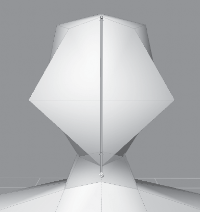
Now that you have created a joint and set the region you want to manipulate based on the weight vector, you need to look at our model to determine whether the origin of rotation is what you need. It is not—because you want to rotate the head at the base of the skull versus the middle of the neck—so you need to move the joint up to that area. Using the Move Pivot tool, click and drag the joint up into the head so it is aligned at the base of the skull, halfway between the bottom of the neck and the top of the head (Figure 6.72). You might need to navigate the camera to a few different angles to make sure your joint is centralized in your model. After you move a joint, it is no longer placed at the center of the joint boundary ring, or your volume, so you will need to adjust it from at least three angles to make sure it is placed where you need it to be.
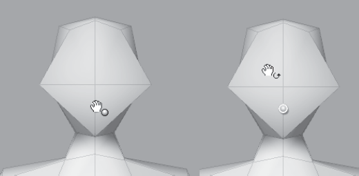
Click on the head sculpt layer in the Sculpt Layers window. You have created a joint and set the area you need to pose, so now you will click the Pose tool to perform the pose. Notice that as you move your cursor onto the model, the cursor changes as you move it onto the pivot versus the rest of the model (Figure 6.73).
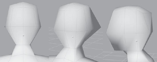
With the cursor on the pivot, click and drag in a left or right motion while pressing the left mouse/stylus button to rotate the head until it is turned slightly left (Figure 6.74).
With the cursor on the pivot, click and drag in an up or down motion while pressing the left mouse/stylus button to rotate the head until it is turned slightly up (Figure 6.75).
While looking at your model head-on, click and drag left or right using the left mouse/stylus button while your cursor is not on the pivot, to tilt the head slightly to the left (Figure 6.76).
With the cursor on the pivot, click and drag while pressing the middle mouse/stylus button to move the head slightly to the left so the neck doesn't look broken (Figure 6.77).
In the Sculpt Tools tray, click the Grab tool. In the Sculpt Layers window, click on the head sculpt layer and adjust its opacity. Notice that the pose will now go from the neutral position you had it in to the posed position. If you are happy with your final pose, leave the opacity at 100. If somewhere in between works better for you, leave the opacity at that level.
That's all there is to the mechanics of posing. The art of posing is something you will work on for a long time.
To pose the ribcage, first select the ribcage sculpt layer in the Sculpt Layers window, and then place a joint around where the belly button would be. Using the Pose tool, pose the ribcage so your model is leaning to the left a little and bending back. Add a little twist of the torso (Figure 6.78).
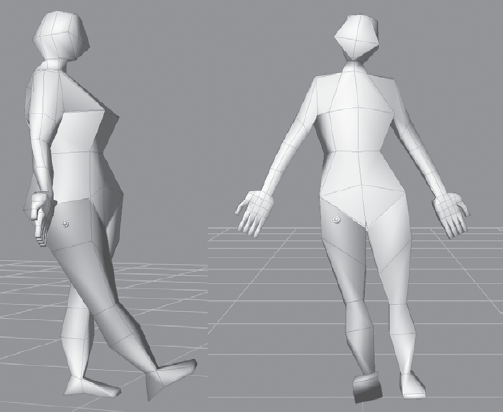
With the Pose tool still selected, click on the ribcage sculpt layer. Using the same methods as before, hold down the Ctrl key and click and drag the model to pose the bottom half of the body. Adjust the legs so they angle back (Figure 6.79). This messes up the plumb line, and makes the model look like it is floating, but you will fix this in the next stage. You have just posed the pelvis.
Next you will pose the legs. Select the
leg_rtlayer in the Sculpt Layers window. Place a joint on the leg (Figure 6.80).Move the pivot to where the ball joint of the femur would be (Figure 6.81).
Use the Weights tool and paint on the pelvis area of the model to remove the weights on that area. Remember that you would need to hold down the Ctrl key to erase. You might want to increase the Strength to 100 to make sure you erase all the weight on the pelvis. Remember that the value of green determines how much an area will move when you pose it.
Use the Pose tool to rotate the leg forward and to the right (Figure 6.82).
Create a new joint at the knee and bend the shin back and out by using the Pose tool (Figure 6.83).
Click on the
leg_lfsculpt layer. Pose the left leg, moving it straight down and in, using the same routine (Figure 6.84).Finally, we will pose the right arm. Click on the
arm_rtsculpt layer to select it. Then place a joint starting on the base of the arm and drag out (Figure 6.85).Move the pivot to where the scapula, or the shoulder blade, would be (Figure 6.86). Remember to move the camera around to make sure that the pivot is where you want it to be inside the model. You might need to use the Weights tool to remove any green shading on the shoulders.
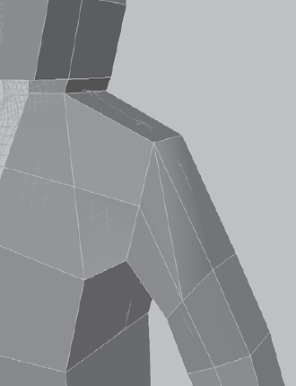
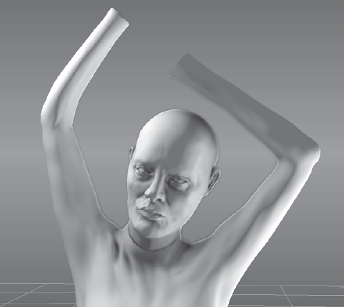
Rotate the arm a little. If the shoulder or the armpit swings out with the arm, use the Weights tool to paint off the weights in that area. Rotate the arm so it is up (Figure 6.87).
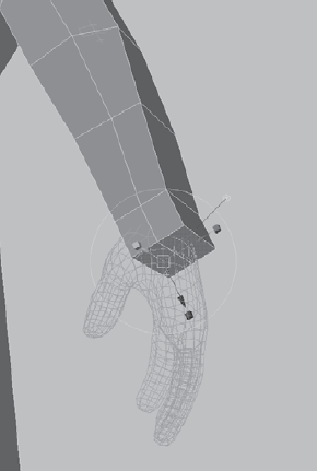
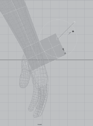
Place a pivot on the elbow and bend the forearm (Figure 6.88).
Place a joint in the middle of the forearm. Click and drag on the pivot to rotate the forearm (Figure 6.88). This rotation can get radical because the of the way the radius and ulna of the forearm twist to accommodate the hand rotating a full 180 degrees. To accommodate for a more radical rotation, you can move the pivot a few times down the forearm and rotate in increments. Pose the other arm the same way.
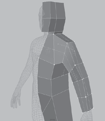
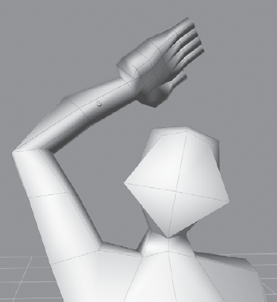
From this point on, we will make adjustments by using the Grab tool. Although a lot of these edits can be made with the posing toolset, it is a lot faster and easier to make the changes by using the Grab tool. Press Shift+D to subdivide the model to level 1. Notice the blocky shapes have become smoother and curvier (Figure 6.89).
Use the Grab tool, and start moving the polygons at this low subdivision level to flesh out the gesture and bring out the major anatomical shapes and dimensions. The pose of the model I am going with is a collage of some reference pictures I have from various fashion pictures I have collected over the years. Go down in subdivision levels to make major adjustments if necessary.
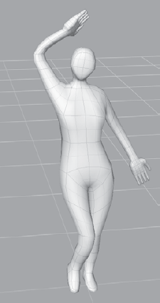
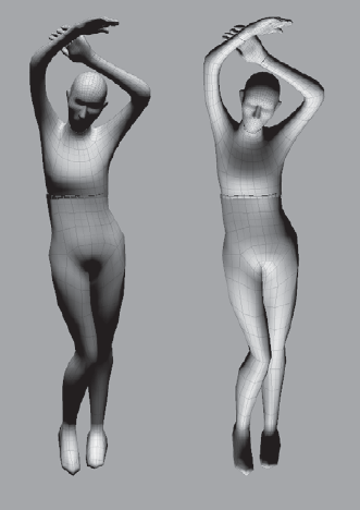
Try the posing tools at subdivision level 1 to see how the tools work at higher resolutions. After working with the model for about 15 to 20 minutes by using the Grab and Smooth tools, I came up with the result in Figure 6.91 that we will take into the next section to further sculpt it.
Now that you have posed the model, it is time to start subdividing and sculpting. However, you are not quite finished with the posing. After subdividing your model, either before or after you start sculpting, you will notice that there are some parts that look out of place with the pose as it pertains to balance, gesture, proportion, or anatomy. Some of these can be fixed with the Grab tool, but certain types of motions, specifically rotation of extremities on a pivot, cannot be accommodated with the Grab tool in Mudbox. You might need to revisit some of the posing toolset and Rotate, Scale, and Translate sections of the model.
Open the file
01_sculptstart.mudfrom theChapter 6�4 - sculptfolder on the DVD (Figure 6.91).Notice that it is the same model we posed earlier. The only difference is that the level 1 subdivided model we worked on in the preceding section has been exported as an
.objfile into Maya and separated into five pieces: the head, body top, body bottom, left hand, andright hand. This has been done by selecting the faces representing the five parts and using the Mesh → Extract function of Maya. The reason for this is that separate pieces can now be individually subdivided to the needed level of detail instead of subdividing the whole model. For example, we will need more geometry to get the details of the face versus the other parts of the body, andinstead of having a very dense model to accommodate for that, we can now subdivide the different parts to the lowest detail level that will give us the polygon resolution we need. The other changeis that the head we started out with has been replaced with thebasic_headmeshthat is provided in Mudbox. The reason for this is that the head mesh provided in Mudbox has better topology than the one we had in our base mesh and it can very easily be translated, scaled, and rotated to fit the same area.You will also notice that the material used is the Gesso material. I find the Gesso material instead of the default glossier brown to be my favorite while sculpting because it does a good job of contrasting light and shadows for the shapes. As I am getting closer to the finished model, I change over to the default material and change the color to white because that adds a little more glossiness and specular highlights to the model. I am sure you either have or will develop your own preferred material to sculpt in.
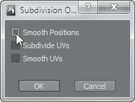
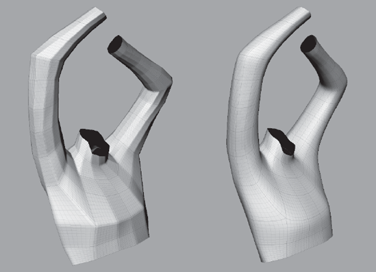
Subdivide the
body_top,body_bottom,hand_lf, andhand_rtparts to level 1 but make sure that you have Smooth Positions deselected in the Subdivision Options dialog box Figure 6.92). This will maintain the form you sculpted in while you posed the model, and works well only if you are going from level 0 to level 1.Make sure you select the Smooth Positions check box for subsequent subdivisions. At higher subdivisions, if this option is not selected, you get a faceted subdivision, and unless you are going for that look, you will have to do a lot of work smoothing out the creased facets (Figure 6.93). With experience, you will learn how a model subdivides and how shapes shift, shrink, and get smoothed by the operation.
At subdivision level 1, use the Grab tool with a large Size to make major adjustments and a small Size to move vertices or proximity of vertices. Remember that the tool will move the polygons on the surface based on your falloff curve.
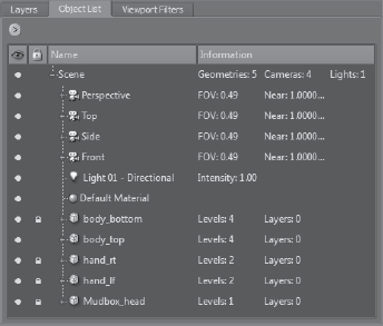
Use the lock capability in the Object List to lock all the meshes of the model you don't want to accidentally manipulate by clicking in the padlock column next to the name of the object (Figure 6.94). You can also use the visibility option to turn visibility of objects on or off if they are getting in the way.
Use the Flatten tool to define planes. Even though you are at this very low level of subdivision, many of the major planes on the body can be defined here—for example, the underarm area, the face, and so forth. Think of these planes as scaffolding on top of which you will build up or down the desired shape on the next subdivision level.
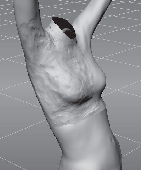
Even at this low subdivision level, you can use the Wax tool to bulge out or push in details where the geometry allows.
Remember to use the Size and Strength keyboard shortcuts to continuously adjust the effect of the tool on the surface. Also remember to constantly keep tumbling around your model to examine your changes from different vantage points to see whether they are working. You might have spent a long time on a feature such as the bulk of the ribcage from one angle and then notice that it completely throws off the physical shape of the ribcage from other angles. Sculpture is created on a three-dimensional canvas and needs to work from any vantage point.
I personally like to sculpt on lower levels with the wireframe on, because topology matters at the lower levels. The last thing you want to do is scrunch up vertices to obtain a shape that would unevenly subdivide certain areas so they do not contain enough geometry, while others have plenty of geometry that is not needed. Much of your sculpting at this level is working on a base-level mesh, so the rules of having a good base mesh carry over, specifically, keeping an even distribution of quads.
Use the Smooth tool to constantly adjust the polygon distribution and smoothness of the surface. Make sure you work with lower strengths so you don't completely smooth out features on the surface. It's better to run over a surface multiple times than to completely erode and smooth out a shape you spent a lot of time developing. While you are tumbling around, also use different shading to see some features that you were not able to see in the default smooth shading.
Right-click in the 3D view and deselect Smooth Shade; this gives you the best depiction of the topology with a faceted version of the model. Right-click in the 3D view again and select Flat Lighting; this will give your model a silhouette look. You might want to tumble around your model with the wireframe on to see whether the silhouette is working, and then for the ultimate test, turn the wireframe off and look at your model. Zoom in and out while you are looking at your model in this silhouette mode (Figure 6.95). If your silhouette works at this level, it will work at every level, because this is the first shape your eyes will interpret. I have found squinting and looking at the model at this stage helps tremendously.
Press l and click-drag your mouse or stylus around to change the lighting on your model. This is also a good way to find areas of the shape of the model that need adjusting (Figure 6.96).
Use the Grab, Smooth, Flatten, and Wax tools to sculpt as much as you can until you start running into the limitations of this subdivision level. You will notice the limitations when you are trying to refine a shape, but you just don't have enough geometry.
Subdivide all the parts of your model to level 2 and continue to refine the shapes by using the preceding methods. Save your model at every subdivision level and at every point that you are satisfied with the result of your work. Remember to also use layers to easily get to a starting point in case things don't go well.
Isolate areas to work on them, or see their cross sections by using the Faces tool from the Select/Move Tools tray to select the faces you want to work on (Figure 6.97). They get highlighted in yellow. Then click Display → Hide Unselected to hide the rest of your model and work only on the desired section. To bring everything on your model back, click Display → Show All, or press the U key.
When you run into the limitations of a subdivision level, subdivide the model and continue using the Grab, Wax, Smooth, Flatten, and Bulge tools to start refining the sculpture. Remember, you can always activate the Smooth tool by pressing the Shift key so you do not have to keep going back and forth between the Smooth tool and the others.
At level 3 you will be able to sculpt some more-defining shapes and details such as folds, indentations, and line definition (Figure 6.98). In my model, I have created the knees and ankles, added some line definition to the shins, and introduced some folds on the pants.
From this point on, the sculpting actions are the same. You subdivide the model and sculpt on it until you run into limitations of the level and need more geometry. Save your work before you subdivide you model, because you might want to go back and modify the model at that lower subdivision state. You could also add your new subdivision level on a new layer, and keep saving the same file. Either way is a good way to go back to the last known good state that your model was in just in case things go awry at the higher subdivision level, which incidentally also affects the lower subdivision levels.
As you get to higher subdivision levels, remember that your file size is growing significantly. That's another reason to exhaust the capacity of a subdivision level before adding another one—so you won't get to higher subdivision levels that add no shape value, and create large files that hinder your productivity by slowing your machine down with the extra geometry.
While working with three-dimensional sculptures, you are constantly dealing with form, volume, and surface. The Mudbox sculpting tools are used to give your sculpture form, to add or subtract volume, and finally to define surface shapes and patterns.
Even though Autodesk has the Sculpt tool as the first tool on the left in the Sculpt Tools tray, I have found the Grab tool to be the tool I use most frequently while sculpting. In fact, I reorder my tools in the frequency I use them, specifically the first four (Figure 6.99).
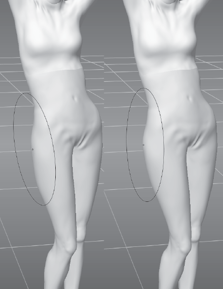
I use the Grab tool frequently to establish form, pushing and pulling volume, and adjusting and moving surface details. You can use the Grab tool to move large volume around, such as adjusting the hip size of our model (Figure 6.100).
The size and falloff of the Grab tool determine how destructive it is to sculpted detail. Therefore, make sure to use an appropriate falloff with enough feathering on the edges (that is, a curve closer to the bottom) to make sure you don't disturb too much detail if you are working at higher subdivision levels. Better still, drop down in subdivision level to do the same action if you don't need to adjust things based on any high-frequency detail.
You can also use the Grab tool with a smaller size and strength to push or pull smaller areas of the surface if the volume you are trying to affect is not uniform—for example, pushing in the inside or pulling out the edges of an ear.
You can also use the Grab tool to adjust the surface by shifting parts along the surface—for example, if you misplace the belly button to the left when you create it, you can use the Grab tool to move it to the right.
Remember to use additive strokes instead of bigger ones until you are fully comfortable with the effect the tool has on the surface. You can of course always use Undo, and sculpt on a layer too.
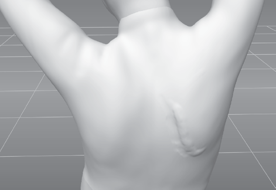
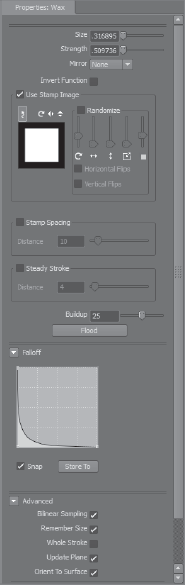
The next tool I use frequently is the Wax tool, paired with a square stamp. I find this tool to be indispensible for adding shaped volume to a model, similar to pressing on clay to a practical sculpture. The inverse effect is also tremendously helpful for subtracting shaped volume (Figure 6.101). You can then use the Smooth tool to smooth out the rough outline. There are many Mudbox digital sculptors who use the Sculpt tool interchangeably with the Wax tool for this purpose; you can experiment with both to determine what works best for your workflow.
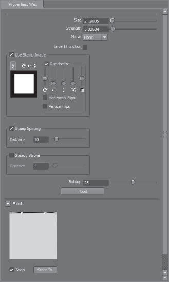
This Wax tool, with minor rotate and strength randomization, and no falloff (Figure 6.102), makes for a good effect of a chiseled surface (Figure 6.103). I use this to sculpt out the rough form, sometimes to smooth out later, and sometimes to give the model the effect of looking like a Giacometti sculpture surface.
To define crisper edges, the tendency of many artists is to use the Pinch tool. However, I get the same results without the cost of scrunched-up geometry by using the Sculpt or Wax tools with a very sharp falloff (Figure 6.104). This will punch in or pull out a sharp line, and you can use the Flatten tool on both sides of the line to get the shape of a sharp edge. You will also want to use Steady Stroke to get straighter edges.
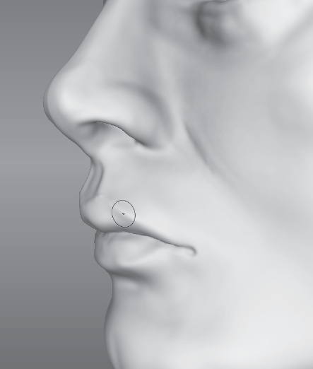
Another extremely useful effect with the Wax tool is to use a sharp falloff and a small brush size to sculpt lines on the surface—for example, the border of the lips as additive (Figure 6.105), or the nasolabial fold as a negative.
The Flatten tool is useful for establishing planes on the surface and smoothing out features in places where the Smooth tool would just soften the details. I find it extremely useful with low strength levels to polish surfaces.
The Bulge tool is also extremely useful for inflating areas. Think of it as an air compressor to inflate areas like a balloon. An example of where the Bulge tool would be useful is on really thin arms that you want to bulk up. The Bulge tool works a lot faster than using the Grab tool on the perimeter.
To readjust the spacing of the quads at the lower subdivision levels, the Smear tool, used sparingly at these levels, redistributes the quad spacing if the Grab or Smooth tools are not doing the job. When you get to the higher subdivision levels, topology does not matter as much if you have done the needed work along the way to make sure you maintain as good a quad distribution as possible. An even subdivision of polygons will give you even geometry to work on in the higher subdivision levels.
I have included my sculpting of the model at various stages on the DVD for you to examine how much work I did before subdividing. I will from this point forward post pictures of the progressat each level and give you any additional guides as to any tools or processes I used that we have not talked about already.
At subdivision level 3 (Figure 6.106), I bulked out the muscle structure and fixed as much of the anatomy as possible, added some clothing wrinkles. On this level, I used mostly the Grab, Wax, Smooth, Flatten, and Bulge tools. I used the Grab tool for pushing and pulling the surface to sculpt the shape. I used Flatten with small strength values to establish the planes. I used Smooth to smooth out areas that get too pixilated or stretch in undesirable directions.
At subdivision level 4, I did some further refining as I did on subdivision level 3 (Figure 6.107).
At subdivision level 5, I started to work on some of the features of the face (Figure 6.108).
This would be a good time to turn on the Ambient Occlusion viewport filter. It will give you a better idea of the finer details introduced at this subdivision level by darkening the occluded areas on the surface.
At this point, I added a couple of Mudbox Sphere primitives to create eyes. I then used the Translate and Scale tools to position them. I then exported and reimported them to overcome the scaling issue.
Your progress on the model from this point on is dependent on your artistic and aesthetic abilities as well as the time you are willing to spend. You can either use my progress to date, modify it, or start a new project of your own with what you have learned. The work is mostly based on repetition of the previous sculpting steps and your knowledge of anatomy, balance, gesture, and aesthetic.
I have included a video, Chapter6-sculpting_Athena.mov, of my following the preceding steps, sculpting various parts of the model, and narrating what I am doing on the Chapter 6Videos folder of the DVD.
A displacement map is a grayscale 2D image that records the height of points on a surface. Even though displacement maps are extremely useful, they record only height information, which means that when we have surfaces that are orthogonal to the displacement, such as undercuts or overhangs, the displacement information represents only the highest surface. Vector displacement maps (VDMs) overcome this issue because a VDM is a 32-bit floating-point color 2D image that records height as well as directional information for points on the model.
We cannot use VDMs to assign topology from an original model or 3D scan to a destination model unless the VDMs have identical vertex topology, or the destination model has an identical subdivision level of the original. If your two models have identical vertex topology or have identical subdivision levels, using a VDM produces no artifacts when you apply the extracted VDM to the target model.
Where VDMs are extremely useful is for creating VDM stencils and stamps that can be used with the 3D sculpting tools to recreate features on the surface of the model.
Remember that your model needs to have UVs in order for you to be able to extract maps. Extracting a VDM is similar to extracting a displacement or normal map with the Maps → Extract Texture Maps command. In the Maps to Generate section of the Extract Texture Maps dialog box, select Vector Displacement Map. Most of the contents of the dialog box should be familiar to you except the Vector Space attribute.
The Vector Space attribute can have one of three values:
Tangent: This default setting indicates a vector space defined by the normal, tangent, and the binormal. You would use this setting if the model deforms during animation.
Object: This indicates the local coordinate space for the model. You would use this method if the model will not need to deform during animation.
World: This indicates the coordinate space of the 3D scene. You would use this if the model is not to be animated or deformed.
Note that the image size will determine the captured detail of the VDM. For extremely detailed models, use higher resolutions. You can extract VDMs from models with UVs outside the 0 to 1 range, in which case, each UV tile is extracted as a separate image file and saved to the extracted files directory. The files will use the naming convention of <filename>_u1_v1_vdm.tiff, where the number value next to the U and V would be the coordinates of the tile.
Follow these steps for an example of how to extract a displacement map and then use it to transfer your sculpture to another surface:
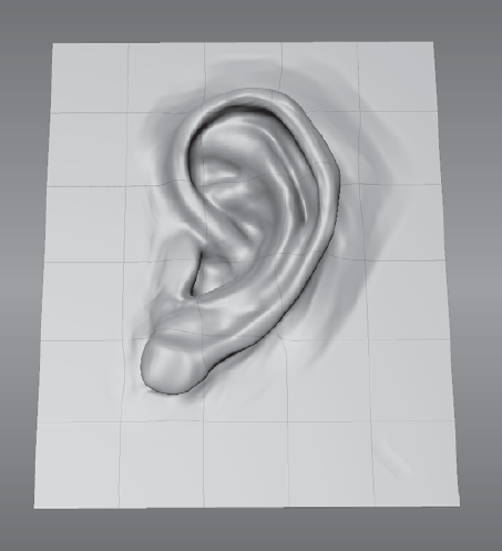
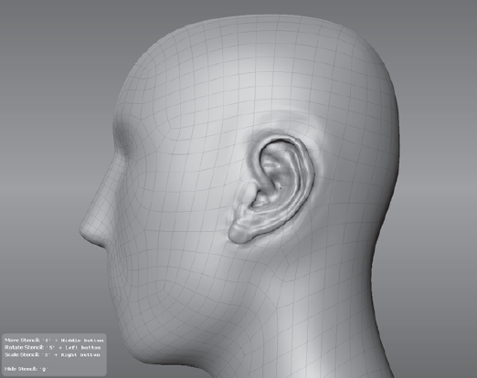
Start Mudbox and load the
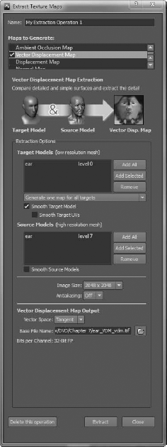
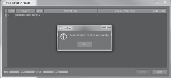
ear.mudfile from the Chapter 6 folder of the DVD (Figure 6.109). This is a model of an ear that I sculpted on a plane when I was practicing sculpting ears. It has seven subdivisions. Click on the ear to select it.Click Maps → Extract Texture Maps → New Operation, and select the Vector Displacement Map check box. The dialog box expands for you to input the VDM extraction parameters. Note that the ear model is loaded at levels 0 and 7, respectively, in the Target Models and Source Models list boxes (Figure 6.110).
Set the image size to 2048 × 2048 and click the folder button to the left of the Base File Name text box. Choose a name and location to save your file. Note that you can choose either the 32-bit
.tifor.exrfile formats.Tangent is the default Vector Space option, and it is fine for what we need.
Click the extract button to create the VDM 2D, 32-bit color image file. When the extraction is finished, you will get a confirmation dialog box. Click OK to close it (Figure 6.111).
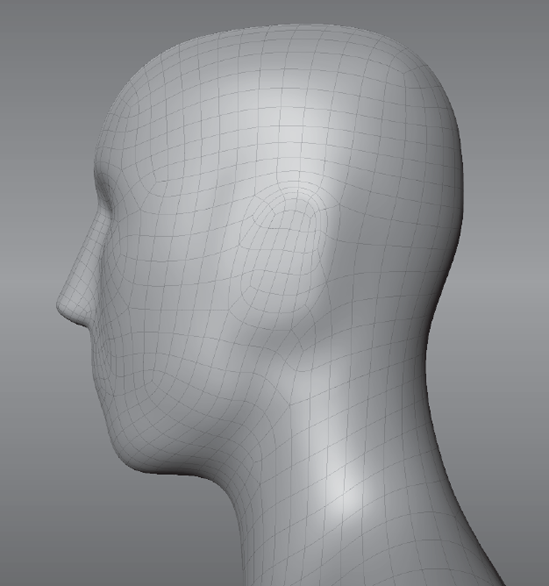
You are now finished with the ear model. Click File → New Scene and create a Basic Head mesh. Select the Flatten sculpting tool and set its Mirror property to X. Press the W key to turn on the wireframe. Flatten the ear protrusions on the model so they are flush with the head (Figure 6.112). You might be tempted to use Smooth, but that contracts the polygons, and you want the topology to stay put. This is a time where the wireframe is indispensible.
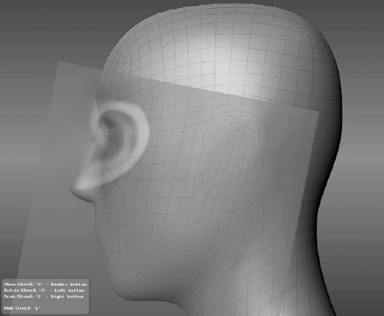
In the Image Browser, navigate to the VDM file you just created and select it as a Stencil. While holding down the S key, align the VDM ear to the head. Based on Edouard Lanteri's location parameters for the top-to-bottom distance of the ears, scale the ear to span the distance from the bottom of the nose to the top of the eyebrow (Figure 6.113). You can adjust the scale of the ear to match that distance on this model and then move the ear to its location (Figure 6.114).
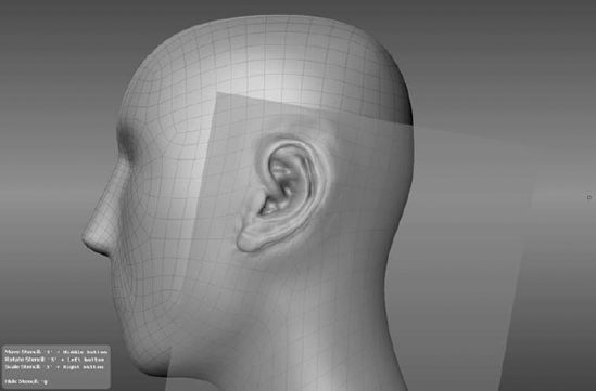
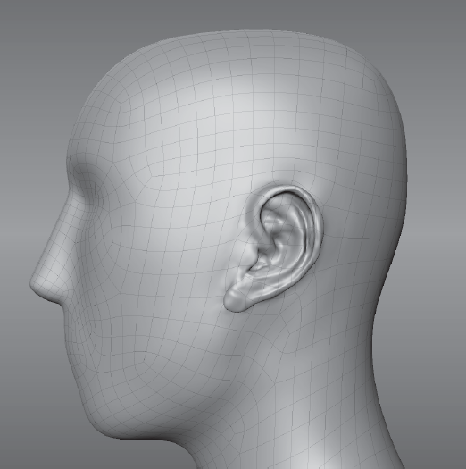
Select the Sculpt tool with the default properties, making sure that the Mirror property is still set to X. Click on the model and drag. This will sculpt the ear with all of its cut-ins and shapes onto the head, and mirror the results to the other side (Figure 6.115).
With some minor sculpting, you can easily fix some of the alignment anomalies and match the ear to the head (Figure 6.116). The mirror option comes in very handy here. You can use this same method for all sorts of details and find it a huge time-saver to create a reference set library of parts to use. You can see a video, Chapter6-VDM.mov, of my going through the exercise steps in the Chapter 6/Videos folder of the DVD.
We have now covered the sculpting capability in Mudbox. In Chapters 1, 3, 5, and 6, you have gone through the process of making a simple shape of an egg and giving it surface details. You have sculpted surface details on a prebuilt model to give it a more realistic look. Finally, you have created a base mesh, made the UVs for it, and then posed it and sculpted on it in Mudbox.
You have gone through the process of planning your sculpture, going through the stages of sculpting, base mesh modeling, creating UVs, and posing the model. You have covered all the sculpting tools and sculpting layer functions. You have also gone through an example showing shortcuts, techniques, and workflow to sculpt a model.
Here is a summary of the points to remember when posing a model:
Pose with the Grab tool first.
Pose your model at the lowest subdivision level possible.
Pose the head, ribcage, and pelvis before the arms and legs.
Pay attention to the balance and weight distribution.
Focus on the gesture and flow of the connecting shapes.
Pose your model on a new sculpt layer.
Here are some summary points on sculpting:
Sculpt around your model Don't stay on one angle or specific feature too long; keep moving around the sculpture as you would when you are working on a three-dimensional object. Camera controls should be second nature to you, and you should be able to move around your model to get to a specific angle without even thinking about it while you work. Sculpt the overall model instead of being stuck working on one specific area. Continuously tumble around your model and work on different areas, and keep thinking of your sculpture as a holistic piece that needs to come together.
Topology Remember to turn Wireframe and Smooth Shading on and off to see how the polygons are deforming under your sculpture. You don't want a large concentration of polygons in a place where you don't need them, and a scarcity of them in an area where you need to sculpt details.
Silhouette Turn on Flat Lighting to see the silhouette of your model, because the silhouette is one of the key ways we recognize and distinguish shapes. Finally, remember to zoom in and out on your model because there are good or bad features that will show up when it is very small. If gesture, shapes, and proportions look good small, it is very likely that they will also look good when you zoom in on the model.
Subdivision levels You need to sculpt at every subdivision level and not just the highest subdivision levels. The lower subdivision levels give you the blocked-in shape. Gesture, balance, and proportion should look good at the lower subdivision levels. Critical landmarks on your model should be sculpted and visible at the lower subdivision levels such as 2 or 3. For example, if you are sculpting a human body, critical anatomical bony landmarks such as the top of the sternum (front center of the ribcage), the olecranon of the ulna (elbow protrusion), the crest of the ilium (the hipbone), the great trochanter of the femur (top of leg bone), and the patella (knee protrusion) should be apparent at the lower subdivision levels. Exhaust what you can sculpt in the lower subdivision level before you move on to the higher one. Also remember that you can go back down to lower subdivision levels when it makes sense to make changes that are more related to the form of your sculpture, without affecting the details on the higher levels.
Sculpt layers Layers are an extremely powerful capability in Mudbox. You can use them for a variety of reasons, such as a save point for when you are sculpting, a variation of the pose of your sculpture, a blend shape, areas that you want to mask from others, or a location to bring in modified versions of your sculpture where you changed the pose or modified the UVs.
Use shortcut keys to make your workflow fast. When you notice that you are pausing to find and click a tool or a feature, make a hot key for it and move it to a location in close proximity of your hand that is on the keyboard. Also remember that your tablet has sensitivity levels, so use that to your advantage to give your strokes a light or heavy touch.
The Grab and Wax tools are the primary workhorse sculpting tools. Use the Grab tool to adjust the overall shape, and the Wax tool to add gesture to the shape. The Flatten and Bulge tools would be the next most frequently used tools. Use the Flatten tool to establish the planes on your model and the Bulge tool to inflate surfaces that are in close proximity where the other tools are not as effective.
Light Make sure to press l and click and drag your stylus or mouse to see your model lit at different angles. The way the surface of your sculpture looks is a product of light and shadow on the surface, and moving the light will reveal your model in a ... well, a whole new light.
In the next chapter, you will see how to bring scan data into Mudbox as yet another way to create models that have a greater resemblance to real people and objects.