
Digital sculpting is one of the two most significant applications of Mudbox, 3D painting being the second. In this chapter and the next, you will focus on the sculpting tools and the workflow to create a digital sculpture. In the next chapter, you will go through a fictional scenario of sculpting a lead female character in pose for a video game.
For this project, you will be in the early stages of development, during which you will need to determine a look for the character. Imagine that the producers and director have asked you to develop the look and come up with some 2D renders and turntables of the character to include in promotional material for the game. You are given little direction except that the character is a synthetic human, 20 to 30 years in age, athletic, nimble, and graceful. In this chapter, we will go over some of the basics leading up to the start of the project in the next chapter. We will cover the following topics:
Understanding digital sculpting
Planning the sculpture
Sculpting in stages
Determining the best base mesh for sculpting
Understanding the Mudbox sculpt tools and their properties
Digital sculpting software is relatively new, and there are significant advances almost annually that enable us to take advantage of the faster processors and graphics card technologies to create amazing art.
There are two areas of expertise required to become a good digital sculptor. First and foremost, you need a strong background in some aspects of fine art that are pertinent to digital sculpting. A solid background in artistic observation, gesture, composition, human and animal anatomy, and three-dimensional sculpting in a traditional physical medium, such as clay, will make a huge difference in the quality of your work. If you don't have this background, there are plenty of excellent schools, extension classes, books, DVDs, and online tutorials that can help. This is an area that all artists continuously develop and cultivate throughout life. The second area of expertise, of course, is understanding the workings of the Mudbox sculpting tools. Knowing which tools to use and developing a quick and smooth workflow will help bring your ideas and visions to fruition.
Planning is best done with a clear vision of the outcome. In production, requirements are handed to you by a producer or art director, and they vary in depth and granularity, ranging from minute detail to very broad-stroke concepts.
The easiest way to start is with concept art, a rough sketch, descriptive words, or reference pictures rather than a blank cube or sphere. As we discussed in Chapter 4, "Painting and Texturing an Imported Model," even if you are given strict guidelines about what is needed, it is always a good idea to gather as much of your own reference material as you can so you can draw inspiration and ideas from it. Do your own research on the topic by spending time finding video footage, images on the Internet, movies, or books on the subject matter. After you are familiar with the subject matter, sketch some examples or use some of your reference material to determine what your sculpture will look like.
It is also a good practice in the planning stages to think about some of the framing angles of your final sculpture. Even though sculpture is three-dimensional, some views will make the best features of the sculpture stand out. Although Michelangelo's David is a masterpiece viewed at any angle, it is placed, lit, and presented in the Gallerie dell'Accademia in a way that represents its best features for visitors. Also, photographers have photographed it at succinct angles that really bring out its beauty. If you are going to present your final material as a 2D image, it is best to have a good idea of which features of your model you will want to highlight.
The next stage in planning is determining the base mesh. In this case, you will model the base mesh in Maya. Even though the Human Body primitive mesh provided in Mudbox is an excellent base mesh to start with, you are going to start with a simpler base mesh that you can more easily pose. This will also be good practice for you, to understand how to build simple base meshes in case the ones provided in Mudbox will not work for your sculpture or subject.
Another important consideration during planning is the final pose in which you will present your character. You should also research this when you are building your reference sheet. Characters are designed, sculpted, and presented in the generic bind pose, similar to the pose that the Mudbox Human Body primitive mesh is in, but as discussed earlier in this book, it makes for a really boring presentation of the character. Although you will model our sculpture in Maya in the bind pose, you will pose the model with Mudbox 2011's new posing tools.
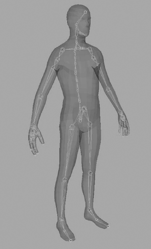
If the model you will be working on is to be animated, chances are that at some point it will undergo rigging in the pipeline's animation software, whether it is Maya, Autodesk Softimage, or 3ds Max. Rigging involves building a skeleton with joints and effectors (Figure 5.1), and then skinning or binding the parts of the model to corresponding areas of the skeleton. After binding the character, weight-painting determines the effect of the skeleton on the various parts of the skeleton rig. Further rigging actions include creating controls that make your model easy to manipulate and animate, and writing animation scripts to automate movement. A well-rigged model will enable you to easily pose the figure in multiple poses and then animate it. However, rigging the model yourself just to pose it is an involved and time-consuming process.
In earlier versions of Mudbox, you or someone else would have had to rig your model, pose it, and bring it in for sculpture. Another option would have been to use the transpose tools in ZBrush or 3D-Coat on your model, which would have required learning another program if you were not already familiar with it. However, the transpose tools in ZBrush are pretty powerful and well worth the investment in time to learn. A couple of excellent books with instruction on the transpose tools are Introducing ZBrush by Eric Keller and ZBrush Character Creation: Advanced Digital Sculpting by Scott Spencer (both published by Sybex in 2008). That said, the Posing toolset introduced in Mudbox 2011 makes it really easy to address most of your posing needs. I will cover the Posing toolset and posing our model in the next chapter.
Another consideration during the planning stage is the UV layout. If your sculpture is to be painted and presented in color, you have to make sure that your model has UVs. After posing our model, you will use Headus UVLayout to lay out the UVs. If you do not have the Headus tool, you can use Maya's UV tools, or whatever UV layout software you are familiar with. In my workflow, I use the tools that I am familiar with to get the fastest acceptable results.
I have found it extremely useful to spend a good chunk of a project's time on the planning stages, and to get as much personal and organizational approval then because it saves me tremendous amounts of time and frustration in the later stages of the work.
Even though certain views and lighting make a sculpture's prominent features stand out and its beauty shine, the sculpture still needs to work from all angles. Taking that into consideration is critical, to make sure the proportions and gesture of a sculpted model work from all angles before doing anything else.
In sculpting, the first stage of our sculpture or model is called the blocking stage. In this stage, we work on the overall shape, proportions, dimensions, flow, and gesture of the sculpture. Even though the outcome of this particular stage might not be very compelling to look at, it is by far the most important stage, because whatever is done correctly or incorrectly in this stage will only be amplified in the stages ahead.
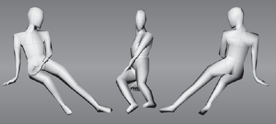
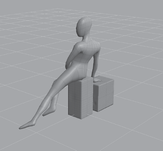
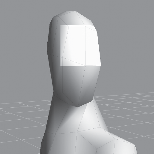
When sculpting in clay, this stage is done by posing an armature and then putting on chunks of clay to get the general shape. In digital sculpting, this sculpting stage is done by creating a base mesh and posing it. There are many approaches to this. You could model and create your base mesh in a pose, or you could model a generic base mesh and pose it after the fact. You don't need a lot of geometry to get the general pose and gesture of a sculpture. In Figure 5.2, you can see that the general pose gesture and flow of the model are visible even though we have used a very low-polygon base mesh of about 600 polygons.
The next stage after the blocked-in model is to sculpt the surface shapes and planes that make up the surface of the model. Look at objects around you and imagine them as three-dimensional objects made of planes. A good example of this is the human head. Although you see no flat planes on a face, there are underlying planes that give the surface its shape. I have provided a Mudbox model on the DVD for you to see the planes of the face; it is called planes_of_the_face.mud and is in the Chapter 5 folder of the DVD (Figure 5.3).
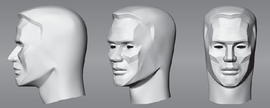
Please note that this model is not a 100 percent accurate representation, and there are some surfaces that look like planes but are not coplanar. However, this model does get the point across of how a human face is composed of different planes, and that these planes vary dramatically in their angles and the lines of intersection that make up the shape of the face.
Load the model from the DVD and tumble around it to get an idea of this concept. A common problem many beginning sculptors run into is not taking planes into consideration while sculpting. This makes their models fall apart the minute they turn it and look at it from a different angle. If you notice this issue with your sculptures, look at objects around you and see if you can determine the planes that make up the shape. It would also be a good idea to pick some of the meshes provided in Mudbox and use the Flatten tool to determine the planes that define the model.
After blocking in and sculpting the surface shapes comes the second sculpting stage that refines, or rounds, the planes to more-organic shapes while your sculpture is still loose and rough. The final stage is sculpting in the fine detail. Because the fine detail is what people see first and find interesting on a subject, beginning artists and sculptors tend to draw or sculpt these before going through the prior stages, and then notice that their sculpture somehow does not work. Perfectly sculpted wrinkles and pores on a face will only amplify mistakes made in the first two stages.
It is critical that you have all your proportions, gestures, and planes correct in the first blocking stage. Then you can focus on refining the shape and finally start adding the surface details.
As mentioned, after you have your concept art, your digital sculpture has to have a starting point. This could be a premodeled mesh that either you or someone else models in a 3D application, or a 3D scan mesh, or one of the provided primitives in Mudbox if your final sculpture falls within the supplied categories. In fact, some of the most amazing digital sculptures I have seen online have started from a cube or sphere.
Remember that all you need to sculpt are polygons, and you could keep subdividing any primitive or mesh to get the polygons you need for the results you want. The challenge with this method is that you could end up taking your digital sculpture in directions requiring you to add parts with new geometry, because the geometry you have is being stretched. For example, say you need a humanoid character with six fingers, and you start out with the Human Body primitive that is provided in Mudbox. You will have to use the Grab tool and pull out the extra two fingers in an area around or between the existing ones. Well, there just isn't enough geometry there to do that, so you will have to subdivide the model to create more geometry. As you are subdividing your model to get enough geometry for the additional two fingers, the ten fingers you started with and the body are getting denser geometry that you do not need. Furthermore, the added geometry is using up your computing resources and slowing down your workflow. The solution to adding more geometry in areas where you don't have it or to changing the underlying starting mesh is to re-topologize your model.
Re-topologizing a model is changing the base topology of the model while maintaining the high-resolution detail. It can be done in many ways. The most common way is to bring a dense version of your high-resolution mesh into a 3D application, such as Maya, 3ds Max, or Softimage, and use the surface of the high-resolution mesh as a template to build a new underlying base mesh. After you have done that, you reapply your already sculpted detail to this new base mesh while also getting the additional geometry needed for the changes. Note that you need to create or modify the UVs for this new base mesh. Mudbox has some powerful capabilities to re-topologize by using its Sculpt Model Using Displacement Map feature. You will see this in the next chapter when you take a dense 3D scan of a head and apply it to better topology.
There are two differing approaches to using a base mesh for digital sculpting.
The first is to start sculpting and to re-topologize at a later point in time. The benefit of this approach is that you have no barrier to your creativity at the onset of the project. You can start with a primitive or a very simple base mesh, and take your sculpture in any direction you desire without any extensive planning or modeling from the onset. However, you might run into a situation where you need more geometry, in which case you would need to interrupt your creative process to re-topologize and then continue sculpting.
The second approach is to give your final sculpture some thought and planning before you begin, and either model or obtain a base mesh that will accommodate the geometry you need for your final result. The benefit of this approach is that you will not have any interruptions during the creative process of sculpting and you could very well take your model to completion without having to re-topologize.
Neither of these approaches is perfect, because sometimes you might start out by sculpting from a primitive and never need to re-topologize, and sometimes you might plan your base mesh ad nauseam and still end up needing to re-topologize. Thus, it is a good idea to know about both approaches and decide which direction to take based on your project.
I presently favor the second approach in my workflow, and start by planning a good base mesh at the outset. However, I know and greatly admire many amazing digital artists who use the first approach of starting with a primitive.
I find that I have better results and a smoother workflow when I start with a base mesh that fits the guidelines discussed in Chapter 3, "Detail-Sculpting an Imported Model," where the geometry is as follows:
Evenly distributed, two-Manifold geometry
Composed of edges with a valency of five or less
Composed of quads
And with UVs, that have these features:
No overlap in UV shells
A spacing of at least 4 to 6 pixels between the UV shells
A correct UV winding order
Minimal stretching or compression
You went through a brief overview of the Sculpt Tools tray and the Sculpt tool properties of the various Mudbox sculpting tools in Chapter 2, "The Mudbox User Interface." In this chapter, you will go deeper into the sculpt tools and their properties to understand how you can use them to bring the intended shapes into your digital sculpture.
The two basic functions we can perform on a surface are either to pull it out or to push it in. With drawing, we balance positive and negative space to represent our intended image. In essence, we do the exact same thing in three dimensions with sculpture: We add or subtract surface depth to get the shapes we want. In Mudbox, we add to or subtract from a surface by pushing or pulling the surface of the model. The various sculpting tools give us the illusion and comfort of using traditional tools to achieve the caking on or scraping off of surfaces, but in essence we are just balancing negative and positive 3D space by pushing in or pulling out geometry. Another important factor in how our eyes recognize the shape of our sculpture is the way light shines off the indentations and protrusions of the surface.
The two most used and universally common properties of every sculpt tool in Mudbox are its Size and Strength properties. The Size property represents how large of an area the tool will impact, and the Strength property represents how deep the tool will push in or pull out the surface. You can manipulate these properties in one of two ways: you can type a value in its field or you can use the B and M keys and click (or tap with a tablet) and drag visual cues on the surface of the model. The Size property is represented by a circle, and the Strength property by a line perpendicular to this circle at the center.
The third-most-used property of a sculpt tool is Invert Function. Every sculpt tool except the Grab tool has this property. The Invert Function property is extremely useful because it inverts the effect the tool has on the surface. For example, if Invert Function is selected, the sculpt tool will depress into the surface of the model (instead of pulling out the surface, as it does when Invert Function is not selected). The check box for this property is useful only if the majority of your strokes are in the reverse orientation of the tool. The best way to get the same effect as Invert Function is to hold down the Ctrl key.
Even though each and every sculpting tool has many properties, there are only a few that you will be constantly manipulating in your workflow while sculpting. These are as follows:
Navigating the 3D view with the Alt key
Changing the tool Size
Changing the tool Strength
Smoothing the model by using the Smooth tool
Changing the effect of the tool on the surface by using Invert Function via the Ctrl key
While sculpting, you can move your cursor back and forth between the model in the 3D view and the Properties tray on the right, but it is infinitely faster for your workflow if you use hot keys for the preceding functions, so you can keep working on your model without having to move back and forth. The following "Expert Tip" indicates are the settings I use; you can use the same ones or come up with your own based on your workflow.
EXPERT TIP
Because you use the Alt key to move the camera around your sculpture, the Ctrl key to invert the function of the brush, and the Shift key to activate the Smooth tool, your hand is constantly pressing and releasing keys in one of the two bottom corners of the keyboard, depending on whether you are right- or left-handed. It's a good idea to place other commonly used functions in this area as well.
For example, because I am right-handed and use the stylus or mouse with my right hand, I use the bottom-left corner of the keyboard to press Alt and Ctrl, I assign the Size function to the Z key (instead of B), and the Strength function to X (instead of M) because it helps my workflow tremendously. I also assign these five keys to the function buttons on the Wacom tablet so that if I am sitting back, and my hand can't reach the keyboard, I can use just the tablet's function keys to perform these functions. The other benefit to keeping your hand in the vicinity of these keys is that you also have very close and easy access to Undo and Redo, which are Ctrl+Z and Shift+Z.
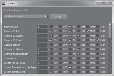
The way to customize keyboard shortcuts is to click Windows → Hotkeys (Window → Hotkeys on the Mac) and find the function in the list of functions in the dialog box, and then type in your desired value. For example, find Change Brush Size and set the key to Z (case does not matter) and LMB (left mouse button), and then find Change Brush Strength and set the key to X and LMB.
Place other tools or options that you use frequently in the same vicinity by using the A, S, D, C, Q, and W keys.
Also note that the tools in the Sculpt Tools tray are mapped to the number keys in the same order as they appear in the initial default setting of the application. So the number 1 on your keyboard corresponds to the Sculpt tool, 2 to the Smooth tool, 3 to the Grab tool, and so forth.
The next important sculpting property is Falloff. The Falloff property is available for all the sculpting tools. Falloff represents a curve that indicates the strength of the tool from its center to its outer edge (Figure 5.4). The leftmost corner of the falloff curve represents the center of the tool, and the rightmost corner represents the edge, so the falloff curve itself represents only half of the tool and is mirrored to the left to encompass the entire brush. The top-to-bottom portion of the falloff curve represents the Strength of the tool.
The shape of the falloff curve can be adjusted by moving the four curve points. The two curve points on each end can be moved only up and down because they represent the center and the edge of the tool. The two center curve points can be moved anywhere in the falloff curve graph area.
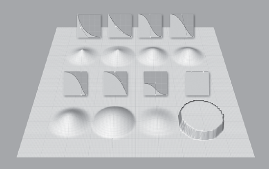
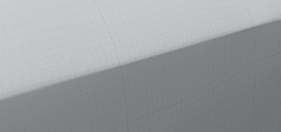
You can make the falloff curve into a straight line for a planar drop-off by aligning the curve points accordingly. Figure 5.5 shows you an example of the default falloff curves in the Falloff tray and their results on a plane. Incidentally, a plane is a great primitive to try out the various sculpting tools with their settings to get a good idea of their function.
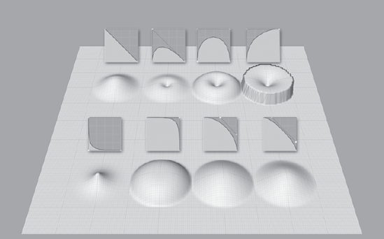
As you make your own falloff curves, you can save them to the tray for future use by clicking the Store To button underneath the falloff curve in the tool Properties tray. The Snap check box allows you to snap the curve points on the grid. Figure 5.6 shows some user-created falloff curves and their result on a plane.
A falloff curve that I use a lot, but that is not part of the default set, is a falloff curve with both middle curve points snapped to the leftmost corner, or center of the brush (Figure 5.7). I use this falloff in addition to the Sculpt tool to create sharp edges instead of using the Pinch tool.
To create this falloff curve, do the following:
In the Sculpt Tools tray, select the Sculpt tool.
In the properties of the Sculpt tool, expand the Falloff section if it is not already expanded.
Select the rightmost curve point and move it to the bottom-right corner.
Select the leftmost curve point and move it to the top-left corner.
Select the two middle curve points, one at a time, and move them to the bottom-left corner.
To add this falloff to your Falloff tray, click the Store To button and select Falloff from the drop-down menu.
Your curve should look like Figure 5.7.
![Sharp-edge falloff brush]](http://imgdetail.ebookreading.net/design/5/9780470537251/9780470537251__introducing-mudboxtm__9780470537251__figs__0507.png)
Besides the Undo function, the other big advantage to digital sculpting is mirroring, or symmetrical sculpting. Using mirroring while sculpting enables you to sculpt one side of your sculpture and have the exact same strokes and shapes mirrored on the other side. Mudbox has some very powerful mirroring capabilities in its sculpting tools.
There are two ways to sculpt when using mirroring, or symmetry. The first is to turn mirroring on and sculpt, in which case the strokes you do on one side are duplicated on the other. The other way is to sculpt one side and then mirror your sculpture after the fact.
The Mirror property, another property that all sculpting tools have, is a drop-down menu that lists the various mirroring options. The first three mirroring options will mirror your work along the world axes. The next three options enable you to mirror along the model's local axes, treating the pivot point, or center of the object, as the center of mirroring.
The last and most unconventionally powerful mirroring option is the Tangent option. This enables you to mirror a topologically symmetrical object along a topological axis that you set up. Topologically symmetrical models have an equal number of faces on each half of the model, even though those faces are in different locations. There is usually a dividing edge loop that divides the model in half.
To work with the mirroring capabilities in Mudbox go through the following steps:
From the Chapter 5 folder on the DVD, load the
pinup_pose.mudfile (Figure 5.8).If the wireframe is not on, press the W key to turn it on. Also, make sure the grid is on by choosing Display → Grid.
From the Sculpt Tools tray, select the Grab tool.
In the Properties tray for the Grab tool, click the Mirror drop-down menu to show the mirror options (Figure 5.9).
Without clicking, move your cursor over the options while looking at the selected cube in the 3D view. Notice how a visual grid pops up in the display to show you the plane of symmetry. As you go through the first six options, you see the plane of symmetry grid; however, when you get to the last option, Tangent, nothing happens.
Experiment while using the Grab tool on the cube by enabling some of the first six mirror options to see the results. After you are finished, select the
pinup_posemodel object from the Object List tray.The
pinup_posemodel is a topologically symmetrical model, even though it is not in a symmetrical pose. The line that divides the model in half that starts at the top of the head and goes all the way to the crotch area is twisted, but there are an equal number of faces on each side of the model divided by that line.Hover the mouse cursor on the model and press Pg Dn to drop the model down one subdivision level, to level 0. We are moving down to the lowest subdivision level because we need to select at least two faces that are adjacent to, and on opposite sides of, the edge loop dividing the model in half. Doing this at the lowest subdivision level is the easiest way because the polygons are large and easy to select, and we can be sure that we are selecting the same number of polygons on each side.
From the Select/Move Tools tray, select the Faces tool.
On the model, select the four left and right faces that make up the face. Click on both sides of the center line of symmetry to select the two faces (Figure 5.10). They become highlighted in yellow. Make sure not to select any other faces besides the four on opposite sides of the center line of symmetry of the face. Alternately, you can select the two faces on the model's back or chest that straddle the center line of symmetry if that is easier for you. If you accidentally select a face you didn't intend to, you can easily deselect it by clicking it again.
Choose Mesh → Set Topological Axis. This picks the line between the selected faces as the axis of symmetry. If this does not turn on Tangent mirroring for you, click the Mirror drop-down menu and select Tangent.
In the Sculpt Tools tray, select the Grab tool and click once on the model.
Hover the mouse cursor on the model and press Pg Up to go up one subdivision level.
Move your cursor on the body of the model and notice how the mirrored cursor moves along the other side. Even though the model is in an asymmetrical pose, we can still sculpt symmetrically.
Press Shift+D until you subdivide your model to level 6. Press W to hide the wireframe.
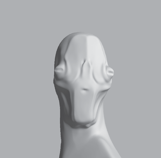
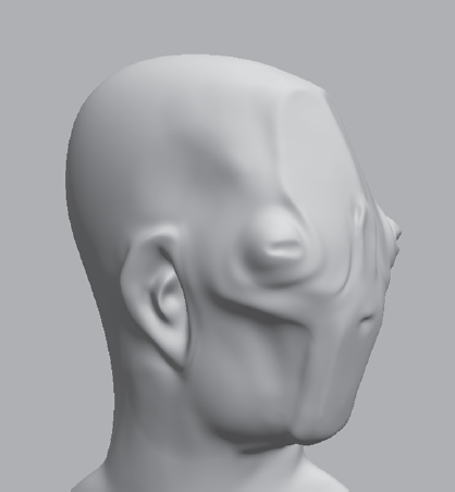
Pick a sculpting tool such as the Wax tool; sculpt on the model to see how it mirrors on the other side. Experiment with different tools, Sizes, Strengths, and Falloffs to sculpt on the face and body to get an idea of how the Tangent Mirror works. Figure 5.11 is an example of what I came up with during 15 minutes of sculpting.

Note
After tangent symmetry is set up, it gets saved with the model so you can use it at a future time.
Symmetry is a huge time-saver and makes our lives a lot easier while sculpting symmetrical subjects. However, at times when you are sculpting, you might forget to turn on symmetry, which could be very frustrating. There are a couple of ways to overcome this.
One solution is to generate a 32-bit displacement map and use a 2D image-manipulation tool that can handle 32-bit images to copy, flip, and paste the sculpture from one side to another.
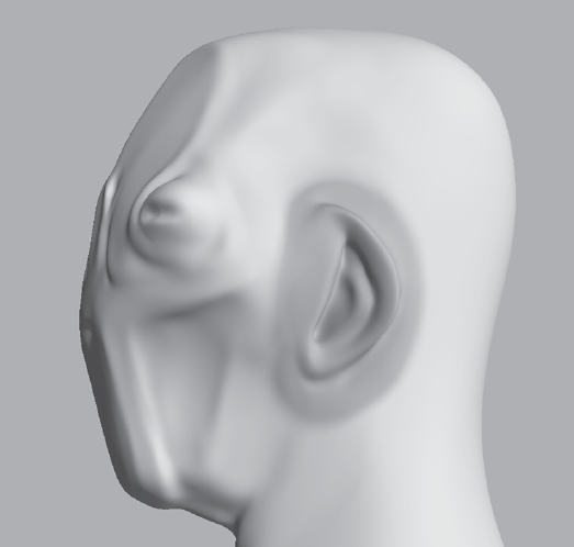
However, there is a way to do this in Mudbox that is a lot easier. For example, say we sculpted the ear on one side of the head and inadvertently turned off tangent symmetry in our model before we started sculpting the ear. There is a way to mirror the ear to the other side after the fact. This works with all mirroring, and luckily also with topological tangent symmetry as well. We will go through this example with the model we have been working on, where we sculpted the ear on one side and need to transfer it over to the other side (Figure 5.12).
From the DVD, load the
ear_symmetry.mudfile from the Chapter 5 folder of the DVD. Tumble the camera around the model to see that there is an ear on the left side, but not on the right.Notice that there is a sculpting layer called
ear_lfin the Layers tray. Mirroring by using this technique works only if you are sculpting on a layer, so make sure that you create at least one sculpting layer, even if you don't need one. Click the view circle next to the layer to hide the ear, then again to show it.In the Freeze tool properties, select Tangent from the Mirror drop-down list. Make sure Strength is set to 100.
Paint the entire ear (Figure 5.13). Note that because we have tangent mirroring on, there is a blue frozen area where we want the new ear to go.
Choose Edit → Invert Freeze to freeze all the geometry except the two ear areas. The entire model is now blue except the two ear areas.
Click the Faces tool in the Select/Move Tools tray and select Off in the Mirror drop-down list, because we want to select only the side we want to mirror to the other side. Click anywhere on the ear to select the side to mirror from. The area you click turns yellow.
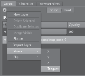
Make sure the
ear_lflayer is selected and click the Layers tray drop-down menu → Mirror → Tangent to mirror the ear to the other side (Figure 5.14).Choose Edit → Unfreeze All to unfreeze the entire model.
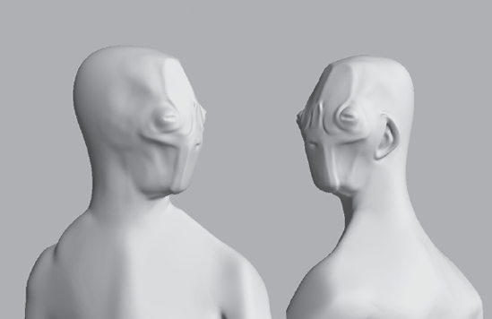
Notice the mirrored ear on the other side. Do some smoothing and cleanup and you are done (Figure 5.15)!
The Use Stamp Image property enables you to use stamp images in combination with the sculpting and paint tools to sculpt or paint with the stamp image as the tip of your tool. This is mostlyuseful to create interesting repeating detail on the surface of your model. For stamps to be effective, you need to make sure that your model is subdivided appropriately to show the granularity level of the stamp on the surface of the geometry.
While sculpting, the stamp image's opacity values are used to mask which parts of the image get modified versus which parts do not. Black values on the stamp image produce absolutely no modification, while white values produce the most; the values in between have changes applied to the geometry based on their value.
To use stamps to sculpt, select the Use Stamp Image check box in the tool's Properties tray. Stamps can be applied with certain levels of uniformity, or randomness, based on the settings of the Use Stamp Image properties.
The stamp image can be flipped and rotated by using the Flip and Rotate buttons on top of the stamp image in the Use Stamp Image properties.
An important capability of using stamps to sculpt is using the Orient to Stroke function. This can be toggled on or off by clicking the Orient to Stroke button above the stamp thumbnail in the Use Stamp Image properties. This will allow the orientation of the stamp to follow the orientation of your stroke (Figure 5.16), like tire tracks orient themselves to the direction of a car.
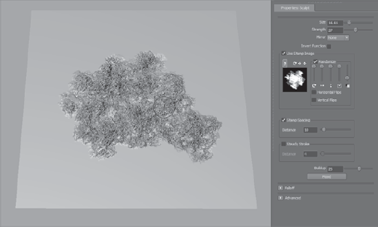
The Randomize option lets you apply randomization based on the sliders to add rotational, horizontal, vertical, scale, and opacity jitter to your stroke with the stamp applied. In Figure 5.17, notice how we get a completely random-looking corroded effect by just using the Sculpt tool with one stamp, and turning on the randomize effects of the Use Stamp Image properties.
The Stamp Spacing property sets the rate at which the stamp image repeats on a stroke. It works whether or not the Use Stamp Image check box is selected. You should manipulate this property only if you want more gaps in your stroke or, more realistically, if you wantnone or fewer.
Steady Stroke is available for all sculpting tools except Imprint. It enables you to sculpt a more even or straighter stroke. This is done by displaying a vector when you begin your stroke. When your stroke has moved the distance specified in the Distance text box of the Steady Stroke property, the stroke is then applied to the model.
Steady Stroke is extremely useful when you want to sculpt lines or patterns that portray a smooth continuity in direction. If you want to sculpt in an actual straight line, or a shape that is more controlled and rigid, you can use the Curves option.
If you work with 2D illustration applications such as Adobe Illustrator, or NURBs in Maya, you are familiar with how useful curves are. In Mudbox, you can use built-in curves and modify them, or you can draw your own curves as guides to sculpt.
The curve tools are found in two places. To create a curve, choose Create → Curves and choose from a Circle, French Curve, Straight Line, or Square. Even though you might not think of straight lines or squares as curves, the reason they are called such is because they are constructed as curves. You can also create a curve by choosing Curves → New Curve and clicking to draw the curve points in the 3D view; use Undo (Ctrl Z) to undo the last point, and press Enter to end the curve creation process. If you want to close your curve, choose Curves → Close Curve.
You can edit the curve by selecting it in the Object List and moving the curve points.
To manipulate a curve, press C on the keyboard and use the left, middle, and right mouse or stylus buttons to rotate, translate, and scale the curve, respectively.
To duplicate a curve, choose Curves → Duplicate Curve.
To snap your tool to the curve to sculpt along it, select the curve in the Object List and press Enter, and then move the cursor to the curve. As it gets close to it, the cursor will snap to the curve.
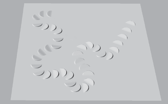
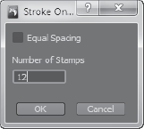
You can sculpt repeating stamp patterns along the curve by choosing Curves → Stroke on Curve and filling in the dialog box with the number of stamps you want on the curve (Figure 5.18). This is very useful if you are going to have a repeating pattern along a curve or line, such as rivets, nails, sewing stitches, staples, and so forth.
Buildup, which is available for the Sculpt, Smooth, Pinch, Flatten, Foamy, Spray, Repeat, Wax, Scrape, Fill, Knife, Smear, Bulge, Amplify, Freeze, and Mask tools, indicates the rate at whichthe tool will reach the Strength value.
For example, if you have a Strength of 100 and a Buildup of 50, you will get to the full Strength value with a very short stroke, whereas if your Buildup value is 10, it will take you longer.
Experiment with strokes on a plane that is subdivided five or six times with the Sculpt toolStrength set at 100 and Buildup at 10, 20, 40, 60, 80, and 100 to see the effects. The default Buildup for the Sculpt tool is 40, just in case you need to set it back to its default value. It's always a good idea to note the default value of a property because it is the value that the developers have deemed as a default average.
Flood, which is available to only the Sculpt, Smooth, Pinch, Flatten, Freeze, Foamy, Spray, Repeat, Wax, Scrape, Fill, Knife, Smear, Bulge, Amplify Mask, and Erase tools, applies the function of these tools uniformly on the entire surface of your model in one click of the Flood button. It's a great way to add uniform thickness and smoothness to the entire model. Note that Flood does not apply the function of the tools to surface areas that are hidden, frozen, or affected by a stencil.
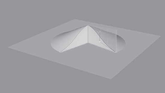
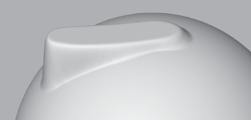
Update Plane is a property of the Flatten, Wax, Scrape, Fill, and Amplify tools, located in the Advanced section of the tool Properties tray. When Update Plane is not selected at the onset of a stroke, a plane is determined based on the stamp's tangency to the contact point, and all the points on the surface are pulled in the direction of that plane for the duration of the stroke. For example, if you start the stroke on a sphere and move to its edge, you will create a plane tangent to the sphere from the point you clicked on it (Figure 5.19).
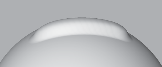
However, with the setting selected, the plane toward which the surface is pulled gets redetermined and updated for each stamp update in a tool stroke (Figure 5.20). Having Update Plane selected is the desired setting while sculpting with the preceding tools, because the brush adheres to the curvature of the sculpted surface instead of the plane of the stroke's initial contact.
Whole Stroke is also a property of the Flatten, Wax, Scrape, Fill, and Amplify tools and is located in the Advanced section. It causes the plane toward which the surface is pulled to be recalculated and updated for each vertex affected by the current tool stroke, as opposed to each stampupdate with the Update Plane function. The result is a slight variation of the Update Plane property, where a more planar effect continues throughout the stroke.
Before we get deeper into the tools, I want to mention that using and developing a large number of sculpting tools is not critical, just as it is not critical when you are doing traditional sculpting. Based on what you are trying to sculpt, you will determine a few tools that work best for you and continue to use those to get the shapes you want. You can customize the settings of a tool and save your custom variant if you discover you are repeating tool customization tasks. Save your custom tool by clicking on the tray's window drop-down menu and then clicking Add Tool.
The Sculpt and Wax tools are the workhorses of Mudbox, especially with the enhancements introduced in Mudbox 2010. In this version, the Update Plane option has been added to the Wax tool, giving it properties similar to adding clay to a traditional sculpture. The Wax tool is best used with the square stamp, to give the illusion of adding strips of clay to your sculpture.
The Flatten tool is another one of the most useful tools in Mudbox. You can use it to define planes while sculpting and to create flat surfaces.
The Foamy tool is a variation of the Sculpt tool with a softer result.
With all the properties and stamps you can apply to these tools, many new implementations remain to be discovered. I will cover a few that I use when we sculpt the model in the next chapter.
The Pinch tool is useful for creating creased corners. However, use it with caution because as it compresses and stretches geometry to create the effect, it creates undesirable topological effects.
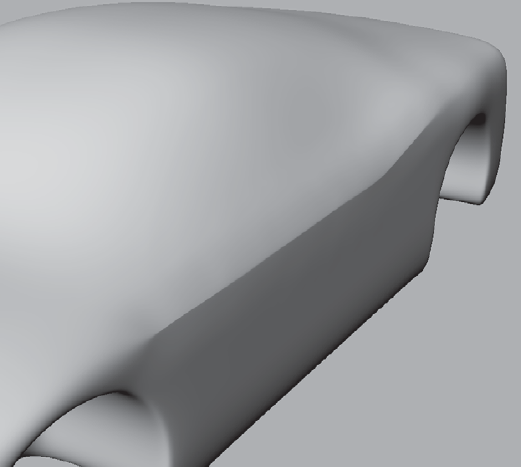
Notice the nice crease created on the edge of a car by using the Pinch tool with Steady Stroke on (Figure 5.21). Although this looks like a nice hard edge, upon further examination, we notice that polygons are crammed in together to produce this crease, while adjacent polygons to those pinched to form the crease are stretched out (Figure 5.22).
The Smear tool has a similar property of moving vertices on the model's surface. The Smear tool could also cause undesirable effects when texturing or sculpting.
The Spray, Repeat, and Imprint tools enable you to place stamps on the surface of your model. You should be familiar with the Spray and Imprint tool because you have used them in previous chapters. The Repeat tool enables you to repeat a stamp along your stroke. This tool is extremely useful for creating repeated patterns such as stitching, rivets, screws, or nails on a path.
Even though you can lock sculpting on an object in the Object List, the Freeze tool enables you to freeze, or lock, certain vertices of the geometry so you cannot modify or sculpt them. The frozen faces get painted blue at varying opacities to indicate the amount of freezing. A fully opaque blue locks completely, while partially opaque blue allows the vertices to move slightly when a sculpting tool is applied.
To paint areas you want frozen, click and paint on the model. The painting takes into consideration all your tool settings such as Size, Strength, Falloff, Buildup, and Steady Stroke. In addition, you can erase the frozen area while holding down Ctrl, and smooth the edges of your frozen area by holding down Shift. Note that to smooth the areas of the edges of a frozen area, you need to have the Smooth & Paint Values check box selected in the Advanced section of the Freeze tool properties tray.
You can freeze your entire selected model by choosing Edit → Freeze Selected. You can invert the frozen areas by choosing Edit → Invert Freeze. To clear all frozen items, choose Edit → Unfreeze All.
If you are familiar with ZBrush, Freeze is analogous to Mask in ZBrush. If you are a user of both applications, note that what is referred to as the Mask function does something completely different in each application.
Both the Erase and Mask tools are used to erase or remove sculpting from layers. Neither one of the two tools works on the base mesh of a model; you have to have at least one sculpting layer to use them.
The Erase tool erases the sculpting on the layer to reveal the original base mesh, or other layers beneath it. Once something is erased, the only way to bring it back is through Undo. If the model is saved and loaded, there is no way to bring back what was erased.
The Erase tool erases sculpting on the current selected layer only. Nothing changes on the other layers or the original base mesh.
The Mask tool does the same thing as the Erase tool, but with a couple of big differences:
It is nondestructive, meaning when you mask out an area, you can restore it by erasing the mask, or inverting the function of the Mask tool by holding down the Ctrl key while applying a stroke to the masked areas of the model. This is stored with the model so you can restore what was masked in later sculpting sessions after the model has been saved and reloaded.
You can mask out with opacity values, which gives you more options and control over what the Erase tool does. This means that when you mask out an area, the Strength setting lets you determine how much depth you are erasing.
To clear the mask completely, turn on Invert Function in the Mask tool properties window, and click Flood.
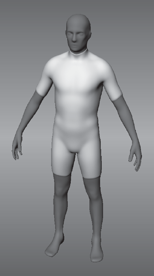
To understand the function of these tools better, you will go through an exercise of using the Mask, Erase, and Freeze tools to add a wetsuit to the Human Body starter mesh. Follow these steps:
Choose File → New Scene to start a new Mudbox session and load the Human Body primitive mesh.
Press Shift+D three times to subdivide your model to level 4.
Create two sculpting layers and name them
wetsuitandHood.Choose the Gesso material from the Material Presets tray.
Click the
wetsuitlayer to select it and click the Sculpt tool to bring up its properties in the Properties tray.Type
0.4in the Strength text box to set the strength of the tool.Click the Flood button in the Sculpt tool properties to flood the wetsuit layer with the Sculpt tool. This makes the model look a little thicker.
Click the Mask tool and make sure you have a Strength of 100 and change the Size to 7 or 8. You will be adjusting the size as you go through the next steps to accommodate for sculpting on the different areas of the model.

Turn on mirroring by selecting Local X from the Mirror drop-down menu in the Mask tool properties.
Use the Mask tool to mask the head, hands, and legs of the model (Figure 5.23).
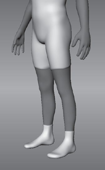
To create dive booties, we need to re-add them. Hold down the Ctrl key and erase the masked area on and above the feet to redraw the booties (Figure 5.24). Remember that you can continually add and subtract the material as needed.
Click the Show/Hide Mask option to hide the reddish hue of the mask. Note that you can toggle the View Layer circle next to the layer name
wetsuitto hide and show the wetsuit layer and reveal your starting figure. Make sure you have thewetsuitlayer visible for the next step.Click the Freeze tool and make sure you have a Strength setting of 100.
Mask out a hood area on the model (Figure 5.25).
Click Edit → Invert Freeze or press Shift+I to invert the frozen area to everything but where we will be adding the hood.
Select the hood layer in the Layers tray.
Click the Sculpt tool and click Flood again in its properties.
Choose Edit → Unfreeze All to unfreeze the body. Notice that the hood now covers the head with a little bit of overhang on the shoulders.
Click the Erase tool and make sure you have a Strength setting of 100.
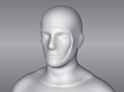
Erase an area on the hood to reveal the face (Figure 5.26). Do this with care, because you cannot add the erased areas back as you were able to with the Mask tool.
Use the Smooth tool to smooth out the lip between the neck of the wetsuit and the hood (Figure 5.26).

As you can see masking, freezing, erasing, and sculpting layers are extremely useful for creating models that can be modified on a layer-by-layer basis.
In this first of our two digital sculpting chapters, you have learned the importance of planning your sculpture, the different stages that a sculpture will go through to get to the final result, and how to determine and plan the base mesh for your sculpture. You also looked deeper into some of the important sculpting tools, their functions, and properties. In the next chapter, you will use these concepts and tools to create a digital sculpture.