It is time to render our scene and transform it into a two-dimensional image or video. Blender 3.0 supports a wide range of professional file formats for images and videos. There are three internal renderers: Eevee, Cycles, and Workbench. It’s also possible to activate Freestyle if we need nonphotorealistic line-based rendering for blueprint and cartoon effects.
We will also talk about compositing and video editing in this chapter. You’ll then have intermediate knowledge of these two topics, without having fully delved into all the details, because of the numerous features that can be used with these two tools. Blender can be used for video editing as a compositor, and a video sequence editor, with a wide range of effects available through the nodal system.
Cycles and Eevee
The Eevee rendering engine
The Cycles rendering engine
Freestyle
Post-processing: the Compositor Editor and the Video Sequence Editor
Comparing Cycles and Eevee
To transform 3D scenes and objects into two-dimensional images or videos, we have to render them. Blender provides us with two render engines with different characteristics: Eevee and Cycles. In Blender 3.0, the developers have improved both renderers.
Eevee is a fast, real-time render engine introduced in Blender 2.8, allowing real-time rendering in the 3D Viewport. It can render PBR materials quickly. In Blender 3.0, Eevee has a new architecture that will serve as the base for future improvements. The Cycles engine takes more time to render but leads to more realistic results. In Blender 3.0, the Cycles X version speeds up render times considerably. Workbench is the third internal renderer, but it is optimized only for better visualization in the 3D Viewport.
I’ve introduced you to the primary features and the fundamental differences between the two renderers in Chapter 1. This chapter will demonstrate the options to fine-tune the result.
Eevee, the Extra Easy Virtual Environment Engine, uses rasterization via OpenGL 3.3. As a result, it’s a very fast, high-quality renderer.
The Cycles renderer is a path tracer, and it works with paths of light. Currently, it gets more photorealistic results than Eevee but is slower.
Workbench allows us to visualize objects in the 3D Viewport easily.
With Freestyle instead, we can achieve cartoon and nonphotorealistic line-rendering effects.

The Blender Viewport in Eevee’s Rendered mode
In the white box highlighted in Figure 6-1 on the right side of the screen in the Properties Editor’s Render Properties panel, we find the button to change the renderer. Here we can switch and select either Eevee or Cycles or Workbench.
Both allow us to work in a real-time viewport preview. However, the Cycles rendering speed is slower than Eevee’s.
The Cycles renderer gives us the possibility to choose CPU or GPU rendering. That is an opportunity to render with the computer’s graphics card or processor. Unfortunately, this is not yet possible in Eevee.
Both support PBR shaders and HDR lighting. We discussed PBR materials in Chapter 4. The first are physically based materials, which mainly consider the interaction between lights and surfaces. The second are high dynamic range images used to illuminate scenes because they allow an increased luminance range.
Finally, both renderers allow VR rendering.
Now let’s see the common standard settings to adjust when running a render.
Cycles and Eevee’s Shared Settings
First, in the Render Properties panel, we see the Sampling window, which is important for the quality of the render with both Eevee and Cycles.
The Samples value is the principal option to control the image quality, both in the render and in the viewport.
The higher the Samples value, the less noise in the final rendered image. But, unfortunately, the counterpart is the slowdown of the rendering times: the higher the samples, the longer the rendering time will be. Then there are numerous values to adjust; we will see how to set options separately for Cycles and Eevee in the subsequent sessions.
At the bottom of the same panel, we can activate Freestyle by selecting the Freestyle box. This renderer creates cartoon effects using contour lines in post-production. We will see this tool in the “Introducing the Freestyle Render” section of this chapter.
Switching instead to the Properties Editor’s Output Properties, we find the other functions to control our image or video features.
Let’s start with the Format panel. We can edit all the options of the rendering format and the resolution on the x- and y-axis (that is, the number of pixels of the rendered image, which allows us to create pictures or videos of any format and resolution). In addition, on the same panel, the Percentage Resolution button enables us to adjust the resolution percentage to create renderings with a different original size without changing the original resolution. The percentage is proper when we want to make test renders, keeping the proportions of the final render and rendering at a smaller size to decrease the rendering time.
Then, in the same panel, we find the frame rate that establishes the ratio between the seconds and the number of frames contained in each second of the movie. Again, this value can vary according to the final file format we want to save our video.
Below, in the Frame Range panel, we have the settings related to the number of the movie’s frames, from Frame Start to Frame End, to determine where we want to begin and end the video.
In the Stereoscopy panel, we find all the settings to set up, both in Eevee and in Cycles, stereoscopic rendering in Blender. Then, we set the 3D rendering mode to select the box next to Stereoscopy.
In the Output panel, we must choose the computer’s folder to save the rendered image or video after selecting the image or video file format, respectively, such as PNG, JPEG, etc., for pictures, and AVI, FFmpeg, etc., for videos.
Then, we can choose one of the Color options to save our image in black and white or color, or we can choose colors with an Alpha channel for transparency after selecting the Color Depth and Compression options.

The Blender viewport in Cycles’ Rendered mode
Figure 6-2 visualizes a preview in Cycles with similar settings as used in Eevee. If we compare Eevee’s Sampling with Cycles, we notice that the samples are the same, but Eevee’s result is much sharper. As we can see when comparing Figures 6-1 with 6-2, the render with Cycles is noisier: we can notice white dots of disturbance, especially in the light reflection points. However, we do not see these disturbances so much in Eevee.
Once the render is made, we can subdivide the image into different layers and passes, working on post-production to realize special effects.
This method allows us to use nodes such as Denoise or passes such as Denoising Data to decrease image noise in post-production for both render engines, as we will see in the exercises of this chapter.
In the following two sections, we see more closely the characteristics of the two renderers. Still, before going deeper into the rendering part, we must introduce two elements of great importance for controlling our renderers: render layers and passes.
Render Layers and Passes
To control the render effects and modify them in the Compositor, Blender provides us with layers and passes. These tools help us limit the impact of nodes to certain parts or characteristics of the image.
Render Layers
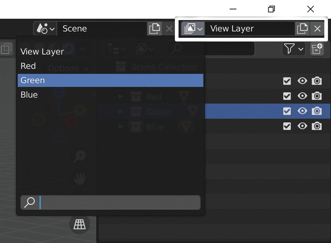
The View Layer box and window

The Exclude from View Layer button
With the render layers, we can apply compositing effects to objects separately, for example, by using a Blur node to the background and not the foreground of an image.
- 1.
Open Blender and activate the Rendered Viewport shading in the 3D view header; then add two cubes to the default cube. Call them Red, Green, and Blue; create simple materials; and give them colors corresponding to the names.
- 2.
Create a collection for each cube, put every cube into a different collection, and give them the name of the cube they contain.
- 3.
Create three new layers by selecting Add View Layer ➤ New. Call them Red, Green, and Blue.
- 4.
Then select the Red layer, and in the Outliner, click the button Exclude from View Layer of the Green and Blue collections.
Repeat the same operation for the other two collections and exclude Red and Blue for the Green layer and Red and Green for the Blue layer.
- 5.
Now, move to the Compositing workspace and activate the button Use Nodes in the header of the Compositor editor.
Render, and you will see the three cubes present in the render. This thing happens because you have rendered the view layer.
- 6.
In the drop-down menu at the bottom of the Render Layers node, select Layer Red and render again. You will see only the red cube, as shown in Figure 6-5.
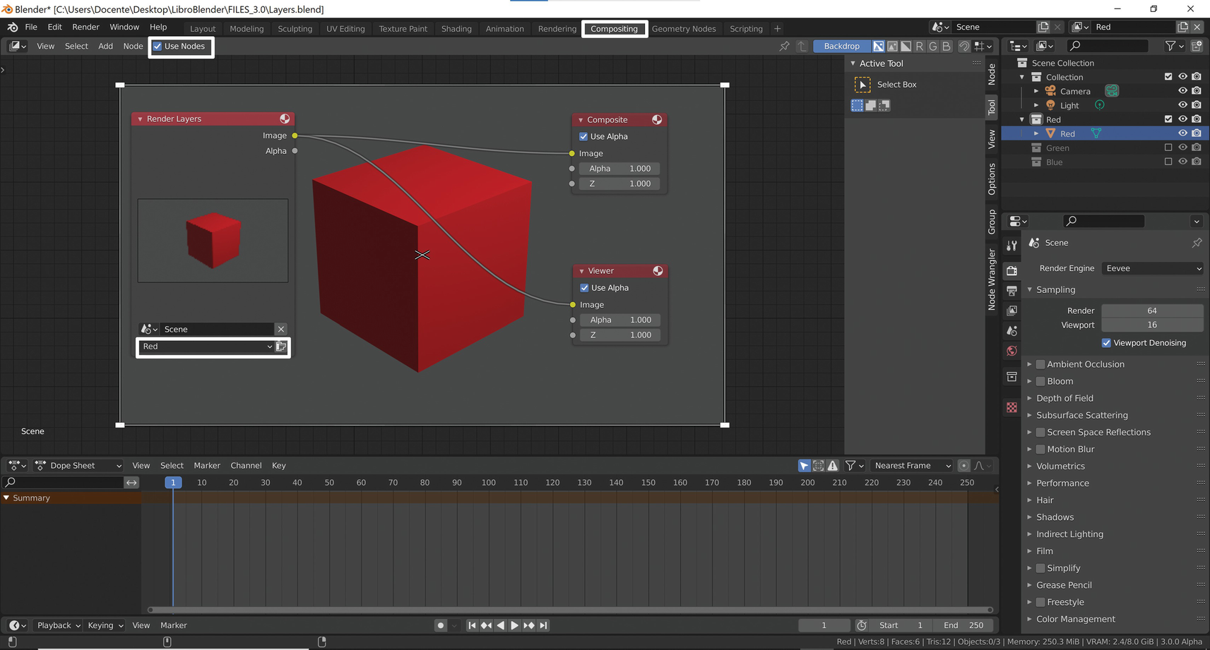
Working with the view layers in the Compositor
In this way, we have divided into three different layers the three objects that later we can edit individually in the Blender Compositor.
Now we see the render passes that have similar characteristics.
Render Passes
Render passes allow us to select information about particular aspects of the rendering. For example, we can use them to separate the rendered images into different colors and lights or get some data separately, such as the 3D data of the scene, like depth.
Once separated with render passes, we can easily edit these data and then reassemble them into a single image.
In the Blender Compositor, we can modify and combine them in various ways to improve the final render result by changing only the elements that interest us.
Combining render layers and render passes allows us to modify our renders in post-production in a flexible way.
Currently, Cycles still has a higher number of passes than Eevee. There are also some differences between the two renderers. For example, Eevee has the Bloom render pass in the Effects category that Cycles does not have.

The Eevee View Layer panel and render passes
The Data category collects 3D information of the scene with nodes like Z, Mist, and Normal.
Light subdivides the data of the different parts of the lighting.
For Cycles, we can separate each type of lighting into Direct, Indirect, and Color for Diffuse, Glossy, etc. Instead, for Eevee, we have a more limited number of light passes.
In addition, there are other types of lighting controls to modify the Emission, Shadow, Ambient Occlusion, etc.
The Effects category is only for Eevee and contains the passes to edit Bloom’s data.
Criptomatte is powerful and is used to create masks for renderings.
For example, Ambient Occlusion extends our control over shadows; Mist instead allows us to control depth of field, etc.
When we activate render passes from the View Layer panel of the Properties Editor, Blender adds the respective output sockets in the Render Layers node of the Compositor to connect them with the inputs of other nodes.
In this way, we can extrapolate the data from part of the rendered image, modify its characteristics, and add it back to the final image.
Now let’s deepen our knowledge of Blender’s two main renderers: Eevee and Cycles. Let’s take a closer look at them.
Rendering with Eevee
The Blender’s default renderer can make a real-time rendering in the 3D Viewport, achieving faster rendering times and creating high-quality images and videos. Eevee supports PBR materials and implements ambient lighting with HDRI effectively.
Cycles and Eevee’s materials use nearly the same shader nodes. Eevee, unlike Cycles, does not calculate the path of each ray of light but uses a different process called rasterization.
This process currently limits the quality of Eevee’s renders with the number of usable lights, shadows, and several other features.
Settings of Eevee
Before starting to work with Eevee, it is advisable to make some changes to the interface to set some essential functions to obtain advanced effects.
- 1.
Open the file Teapot.
- 2.
To get a real-time rendering, press the Z key, choose Rendered in the menu, or click Rendered in the Viewport Shading display on the right of the 3D view header as shown in Figure 6-7.
- 3.
In the 3D view header, disable the buttons Show Gizmo and Show Overlays, highlighted in Figure 6-7. So, you hide all the gizmos and outlines and get the detailed preview of the final render in the viewport.

The Show Gizmo and Show Overlays buttons
- 4.
Then move to the Properties Editor’s Render Properties panel and activate the Ambient Occlusion, Bloom, and Screen Space Reflections buttons. Then enable Refraction in the Screen Space Reflections window.
Enabling Ambient Occlusion improves the objects’ shading and adds realism to local reflection patterns.
Activating Bloom, you add glow to materials and create brighter pixels. You can control the intensity with the Threshold value in the Bloom window.
Instead, the Screen Space Reflections option creates reflections and refraction effects on materials. It is essential for glass. In the same window, to improve the quality, you can disable Half Res Trace.
But to have good reflections on materials, you must also enable Screen Space Refraction in the Material Properties and select Settings.
- 5.
To check the camera’s focus, select it and reactivate Show Overlays in the 3D Viewport header. Then, in the Properties Editor, from Object Data ➤ Viewport Display, select the Limits box. Select the Depth of Field box, from the path Properties Editor ➤ Object Data. Then modify the Focus Distance value, and see that in 3D view, a yellow cross moves on a line that indicates the camera’s focus. Finally, by pressing 0 in the Numpad, activate the camera view. Notice that you can control the focus distance just as you used a real camera, as shown in Figure 6-8. With F-Stop we can control the depth of field. Decreasing the value decreases the area where objects still appear sharp and increases the blurring effect on more distant objects.

Modifying the depth of field
- 6.
As far as shadows are concerned, we also need to adjust some parameters.
First, in the Properties Editor, go to Render ➤ Shadows and change the Cube Size value from 512 to 1024. Then, to further improve the quality of the shadows, we can also check the High Bitdepth box.
We can also increase the incidence of shadows by unchecking the box Soft Shadows.
- 7.
To further improve how the shadows render, we can also activate Overscan from the Properties Editor by selecting Render ➤ Film. We can also enable the Alpha channel for the background in the render by clicking the Transparent box to get a transparent background.
- 8.
It is also vital to enable the contact shadows of the lights by selecting each light, selecting the box Contact Shadows in the Properties Editor under Object Data Properties, and increasing the Thickness value to cover the shadows zones in the point closest to the objects.
- 9.
To get more contrast in the render in the Properties Editor’s Render Properties ➤ Color Management window, we can modify the light difference by changing the Look value from None to Medium High Contrast, High Contrast, etc.
In this way, we have set a suitable file for our renders in Eevee.
After setting some crucial values in Eevee render engine, we see how to perform the same operations in Cycles for the same scene.
Rendering with Cycles
At the moment, this engine allows us to get better photorealistic results than Eevee, even if with longer rendering times. The arrival of Cycles X shortens rendering times and does not change the features from the original Cycles interface. In Blender 3.0, Cycles X is four to eight times faster than Cycles when rendering the same scene.
As we have already said, it is a physically based path tracer that supports PBR materials, has excellent flexibility, and obtains incredible realism in the results. The renderer set in Blender 3.0 is Eevee, so to use Cycles, we have to choose it in the Properties Editor’s Render Properties ➤ Render Engine.
The most important thing to do when using Cycles is to optimize the rendering time.
The Cycles renderer calculates the reflections of light on the surface in a similar way to the real world because, from every source of light, it calculates the rays that bounce in the scene reflecting the light itself. The effect is realistic, and we set up the options faster than Eevee.
Long rendering times are the other side of the coin.
- 1.
Select Edit ➤ Preferences in the Topbar and open the Blender Preferences window. Next, select the System panel on the left side of the Blender Preferences window.
Then in the Cycles Render Devices panel, enable CUDA or OptiX if you use an Nvidia Graphics Card or HIP if you use an AMD graphics card.
This option allows you to choose the Blender hardware tool to render: the processor or the graphics card.
- 2.
Also, in the Properties Editor’s Render Properties ➤ Scene, click the drop-down in Device next to the CPU down arrow. Select GPU Compute. Render Engine, of course, must be set to Cycles because Eevee does not support this option yet.
From now on, Cycles X will use the graphics card to render instead of the computer’s processor. This feature can significantly speed up rendering times. But let’s see Cycle’s main settings.
Setting of Cycles
To compare the results of the two rendering engines, we now render with Cycles the same scene as Eevee. The Cycles renderer is already preset to realistic render, and it is not necessary to change all the settings as we have that we set up in Eevee.
The most important thing for quality rendering in Cycles is the Sample setting in the Sampling window. If we increase the samples, we enhance the quality of the rendered image, but we extend the rendering time.
In the last versions, however, we are provided with the Denoise node that helps to decrease the disturbance created by a low number of samples.

Modifying the depth of field
So in Blender 3.0, it is advisable to set the Noise Threshold value and let Cycles do the work. It will analyze the noise level of the render, and it will automatically set the necessary samples per pixel within the number of samples we have given it in the Min and Max Samples boxes.
It is advisable to keep Noise Threshold values from 0,1 to 0,001.
Lower values mean less noise.
We can also set a maximum time with the option Time Limit for the rendering in the Render panel of the Render Properties. And, always in the Render window, the Denoise box is also active by default.
It is elementary!
- 1.
So, reopen the file Teapot, where you set the options for Eevee, and rename it Cycles. Then, press the Z key and choose Rendered in the menu or click Rendered in the 3D view header’s Viewport Shading.
- 2.
Run a rendering with Eevee to compare it later with Cycles.
The image obtained is in Slot 1, set by default, as shown in the header of the Blender Render window, in Figure 6-10.
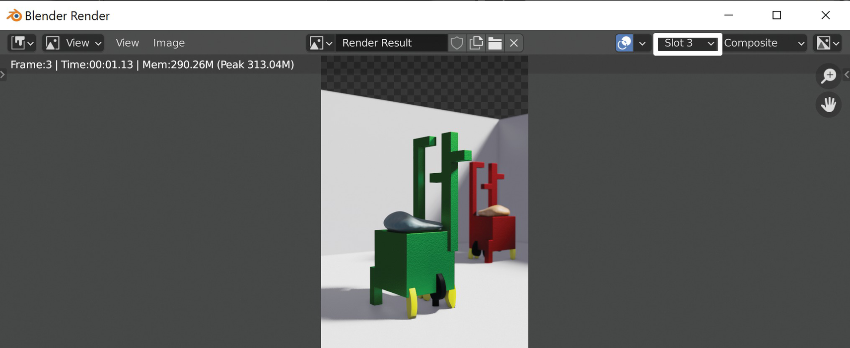
The Blender Render window
In the Blender Render window, on the right of the Blender Render header, we click the Select Slot button set to slot 1. Other slots appear.
- 3.
Click Slot 1 and select Slot 2. Cycles will place the following renderings on this slot, keeping that one on slot 1.
Warning, though, because Blender will save the images only temporarily, and this operation is not equivalent to saving the rendering but only helps to compare the different versions.
- 4.
Change the render engine from Eevee to Cycles in the Render Properties panel. Many options in the Properties Editor will change contextually, and the real-time view navigation will become slower if we have enabled Rendered Viewport Shading.
If real-time rendering becomes too slow from the Properties Editor’s Render Properties ➤ Performance ➤ Viewport window, change the Pixel Size value from Automatic to a precise value that could be 2x. So, while the rendering quality in the viewport decreases, the browsing time will become faster.
- 5.
Run the render with Cycles on slot 2.
Then switching from slot 1 to slot 2, you can easily compare the results of the two render engines.
- 6.
Let’s save the file Chair_Cycles.blend.
At first glance already, we can see that the results of Cycles, compared to those of Eevee, have softer lighting, more diffused light, less dark shadows, and more defined details.
However, we can also say that the sharp and well-defined image of Eevee is, in some ways, more captivating than that of Cycles.
We can improve our renders by modifying the colors, modifying the contrast, and creating special effects. Still, we will deepen the various rendering systems with Eevee and Cycles in the exercises later in this chapter.
Now let’s see Freestyle.
Introducing the Freestyle Render
Before using Blender as a Compositor and Video Editor, we introduce a device to get cartoon effects and line-only special effects in post-production rendering.
With Freestyle, we can create the contour lines of our render geometries. In Blender 3.0, the developers have modified the interface a little.
The Freestyle space reproduces the contours of three-dimensional objects according to various settings in the rendering control panels.
It is a nonphotorealistic (NPR) rendering engine edge/line-based, which allows us to obtain a two-dimensional drawing while rendering three-dimensional objects quickly.
Freestyle allows us to render different line styles to simulate drawings with a technical or artistic stroke, hand-painted drawings, or cartoons. Thus, we can use it for technical drawings, graphics, or cartoon styles.
We can modify the line style and parameters in a predefined way. For example, we can create a sketch with defined contours with different thicknesses or simple volumes, substantial distortions, etc.
Using Freestyle

The checkbox to activate the Freestyle renderer
We can directly control the Line Thickness Mode value and the Line Thickness value from this panel.
We must select Absolute for a constant line thickness.
Instead, we can use Relative for a variable line thickness, which is one pixel of width every 480 pixels of the height of the rendered image.
From the same panel, we control the Line Thickness value. This box holds the line thickness in pixels when the Absolute line thickness mode is active.
First, we must consider that Freestyle does not render objects without surfaces.
We find the Freestyle settings in the Properties Editor’s View Layer Properties.
Freestyle, which contains the most general settings
Freestyle Line Set, which includes the contour line settings
Freestyle Strokes, which controls the properties of the final lines to render
Freestyle Color, which defines the stroke’s color
Freestyle Alpha, which modifies the line transparency
Freestyle Thickness, which establishes Freestyle Stroke thickness
Freestyle Geometry, which alters the geometry of the line
Freestyle Texture, which creates a texture
Let’s see what we can do with these panels.
The Freestyle Panel

The Freestyle panel
In the Control Mode box, we can choose between two options.
The Parameter Editor mode allows us to define the settings with manual control through the Parameter Editor.
Instead, the Python Scripting mode allows us to create scripting in Python to define the settings and control the rendering more precisely.
Moreover, in the Edge Detection window, we determine the Crease Angle value, the minimum angle between two faces to display the edges in the rendering. Above this angle, the strokes are invisible.
The out-of-view edges are invisible if we enable the Culling box.
If we check the box Face Smoothness, Freestyle will consider the Shade Smooth/Shade Flat option we can activate and deactivate on the Object context menu.
This panel has two other options: Spere Radius and Kr Derivative Epsilon. These are helpful when rendering more complex human characters or organic objects.
The second panel to control the render is Freestyle Line Set.
The Freestyle Line Set Panel
In this panel, we begin to control the lines’ characteristics to render precisely. Here we can select the lines generated according to a predefined line style.

The Freestyle Line Set panel
Visibility selects the contours to render based on their viewability.
Edge Type chooses the edges to show based on the different edge types.
Face Marks selects the silhouettes to render based on the marked faces.
Collection renders the contours based on the different groups of the Outliner Editor. So we can choose to render with a particular LineSet all the objects of a collection.
In the Visibility section, we can select what Freestyle will display or not in the rendering, by settings things to visible or hidden, or based on quantitative visibility.
Silhouette creates the edges at the boundary of the objects.
Crease shows the edges between two faces whose angle is less than the Crease Angle in Edge Detection value.
Border renders the border of the open meshes.
Edge Mark renders edges marked with the Mark Freestyle Edge button that we can find in the path Edit Mode ➤ Edge ➤ Mark Freestyle Edge from the menu of the 3D view header.
Contour renders the outer shapes of objects.
External Contour renders the outer contours.
Material Boundary renders the contours between two different materials.
Suggestive Contour renders contours randomly;
Ridge and Valley render contour lines between concave and convex surfaces.
We then have six more panels dedicated to the display control of the rendering line style.
Let’s see the first three in the following section.
The Strokes, Color, and Alpha Panels
In the previous versions of Blender, the Freestyle Line Style panel grouped these three windows and the other three of the following section.
In version 3.0, developers have subdivided the tools into six panels, each dedicated to a specific purpose.
The first is Freestyle Stroke, which selects the final lines’ properties to render.
We can modify the strokes in different ways. So we can create effects of continuous or dashed lines and so on in an exact way.
Instead, the Freestyle Color panel determines the lines’ color. First, we have to select a primary color. Then we can choose different modifiers to modify it such as Along Stroke, Crease Angle, Curvature 3D, Distance from Camera, Distance from Object, Material, Noise, and Tangent, which we will see shortly.
The third window, Freestyle Alpha, modifies the transparency channel. Also, in this panel, we have at our disposal the same modifiers of the Color panel to change the final result of the rendering.
The Thickness, Geometry, and Texture Panels
Three other panels allow us to control the effects of Thickness, Geometry, and Texture.
Freestyle Thickness controls the stroke thickness. Also, in this case, we can apply the following modifiers: Along Stroke, Calligraphy, Crease Angle, Curvature 3D, Distance from Camera, Distance from Object, Material, Noise, and Tangent.
We use the Freestyle Geometry window to modify the geometry of the line.
In this panel, the modifiers are many and obtain the most varied line types.
The last panel, Freestyle Texture, allows us to create a texture assigned directly to the strokes at rendering time. We can set an image texture. Checking the Use Nodes box, we can also operate with the different Blender procedural textures.
Now let’s see modifiers more closely.
The Freestyle Modifiers
To conclude this introduction to Freestyle, let’s see the Freestyle modifiers to edit Color, Alpha, Thickness, and Geometry.
We use these tools to introduce changes in the various parameters of the rendered line. Let’s see the most important ones.
Along Stroke
This modifier applies a linear variation of color, transparency, and thickness to the lines.
Calligraphy
This is only for line thickness; it creates different thicknesses concerning the line orientation and imitates some signs such as fountain and calligraphy pens.
Crease Angle
This modifies the strokes according to the angle between two adjacent faces. If the faces do not form the corner within the values defined in the window, the line is not modified.
Curvature 3D
This modifies the line by referring to the radial curvature of the underlying 3D surface.
Distance from Camera
This creates different types of thickness related to the distance of the object from the camera.
Distance from Object
This modifier edits strokes according to the distance from a specific object.
Material
The material modifier changes the base properties of color, thickness, and transparency, referring to the material of a particular object.
Noise
The noise modifier distributes a disturbance along the lines of the drawing to make its characteristics irregular.
Tangent
This changes its effect concerning the direction of the lines evaluated at the vertices of the drawing.
More on Freestyle
We can use this renderer to make technical drawings or free-hand sketches.
We can combine Freestyle’s contour lines and effects with Eevee and Cycles’ materials to mix cartoon with photorealistic results.
We introduced here the main elements of this particular renderer.
To deepen this topic, we can refer to https://docs.blender.org/manual/en/3.0/render/freestyle/parameter_editor/index.html that leads us to the part of the Blender Manual site dedicated to Freestyle.
Now let’s see how to use Blender for post-production.
Compositing
After seeing the features of Blender renderers, we will move on to post-production with compositing. The Blender Compositor allows us to edit and enhance images and videos.
We can improve our renders by modifying the color, contrast, and special effects. We can do all this in the Compositor through the nodal system. We already saw how nodes work with materials in Chapter 4. We will learn about post-processing with the Blender Compositor to improve our renders, images, and videos.
The Compositor Workspace
In the Blender Compositor, we can edit a video, an image, or a sequence of images.
For example, we can merge two movies with Compositing nodes and edit the whole sequence altogether. Moreover, we can import images or videos, edit them, and add many special effects through nodes.

The Compositing workspace
The default interface presents the Compositor as the main window. Below this window, there are the Dope Sheet and the Timeline. Finally, on the right of the interface, we find the Outliner and the Properties Editor.

The Compositor with Render Layers and Composite nodes
The Render Layers node lets us input the scene in the Compositor and connect it to the Composite node. In addition, with the Render Layers node, we modify the render passes that help us control which image data to use to edit the scene image.
Instead, the Composite node is the final output of the entire blockchain and contains the modified final image.
We don’t have any Render Layers node image available at the moment because we haven’t launched a render yet.
However, we can do it from the Topbar in the main menu by selecting Render ➤ Render image or directly from the Compositor by clicking the Render Active Scene button at the bottom-right corner of the Render Layers node.
Before executing the render, let’s move to the Properties Editor’s View Layer Properties ➤ Passes ➤ Data and activate two passes: Mist and Normal. Automatically in the Render Layers node the output sockets of the two nodes will appear. These two functions will help us have better compositional results adding a more specific control over the render display.
Now we play the render again. Again, the rendered image automatically updates in the Render Layers node.
We use the shortcut Ctrl+Shift+LMB in the Render Layers node to see the render preview in the window’s background; this operation also creates a Viewer node.
We also preview each output channel of the Render Layers node in the Backdrop by clicking Ctrl+Shift+RMB on the individual output sockets of the various passes. We can change the size and position of the background image in different ways. We use the shortcut V to zoom out and reduce the image, while we use Alt+V to zoom in and close the picture. Also, we can zoom in and out or move our backdrop image, modifying the values of the Zoom and Offset boxes of the View panel in the Sidebar we open and close with N.
Now let’s see how the Compositor works in practice.
Setting the Compositor
First, we set the compositor interface to work on the 3D view rendered image.
- 1.
Open the Teapot.blend file previously created and save it as Teapot_Compositor.blend.
- 2.
Choose Eevee or Cycles. Then, from the Properties Editor, select Output, set the Resolution Percentage setting of the Dimensions panel to 50 percent, and render.
- 3.
Click the Compositing workspace, and activate Use Nodes. Then click the Backdrop button on the right side of the Compositor header.
- 4.
Click the Image output in the Render Layer node by pressing Shift+Ctrl+LMB and add a Viewer node to the node chain. The Render Output Image appears as the background of the window.
By selecting the Viewer node and clicking the two crossed diagonals in the center of the background image, we can move the backdrop. Then, clicking one of the white rectangles in the corners of the image, we can resize it. In this way, we can place the image as we wish.
With the shortcut Ctrl+spacebar, we can maximize and minimize the entire window to more easily perform our movements.
We find the same commands in the View panel on the Sidebar to the right of the View window that we can open with N.
Up to now, we have adjusted the interface setup. Now let’s learn how to create a newly rendered Image with a few samples.
The Denoise Node
There will be a very accentuated image disturbance in a render with Cycles with few samples.
But even with Eevee, samples improve the rendering quality but lengthen the rendering time. So, we must use as few samples as possible with Cycles and Eevee.
We can reduce the render noise with a simple post-production modification.
In Blender 3.0 for the Cycles renderer, we can use the Denoise boxes for Viewport and Render from the Properties Editor: Render Properties ➤ Sampling path. This operation allows us to control noise in both the viewport and the render.
Instead, in Eevee, we must use the Denoise node. With this tool, we reduce the rendering time by using a low number of samples for the render but maintaining a good quality for the final render result.
Let’s go back to the Compositing workspace and add a Denoise node in the Compositor.
It has several inputs; we connect the output image of the Render Layers node with the input Image of the Denoise node.

The nodal chain with the addition of the Denoise node
By adding the Denoise node, we get a noticeable image improvement compared to the original render. We performed the render in Figure 6-16 using Eevee, with the Sampling Value set at 2 for Render and Viewport.
We can set the samples in the Properties Editor by selecting the Render Properties ➤ Sampling window, and in this case, the disturbing effect in the original render is evident. However, as we see in Figure 6-16, the final image improves considerably with the addition of the Denoise node in post-production.
We can use this node also in Cycles.
In Blender 3.0, the Denoise box in the Render window is selected by default.
Moreover, in Cycles, by clicking in the Properties Editor, selecting View Layer Properties ➤ Passes ➤ Data, and checking Denoising Data, we add several other passes to the Render Layers node. We can use them to refine the effect and control it more precisely through the specific passes for editing images or videos. Next, in this chapter, we’ll see how to use them in practice in Exercise 14.
Now let’s delve into the topic, analyzing the most crucial Compositing nodes individually.
Compositing Nodes
These nodes allow us to work in post-production directly in Blender on external videos and images or directly inside Blender.
These video editing tools allow us to assemble and improve our multimedia content.
This part of the chapter will discuss the different types of nodes for compositing. Blender offers many of them divided into ten different categories. There are many nodes, and we will get an idea of their characteristics and how we can use many of them.
Input Nodes
We use input nodes to enter information in a node chain. They are the first link in the chain, with only an output socket and no input. We can import images, videos, colors, and textures with this node type.
Bokeh Image Node
This node generates blurs in a render. Therefore, we need to connect it to a Bokeh Blur node to make it work.
It simulates camera parameters such as lens distortions and aperture shape to create effects in the blurred parts of the image rendered.
Image Node
We use this node to import images in the Blender Compositor.
There are two output sockets:
We use the Image output when we want to utilize all image data.
We use Alpha output when we want to use transparency data only.
We can load the image from the New and Open buttons at the bottom of the interface.
Mask Node
The Mask node allows us to use the mask data-block to control the effects applied to an image. For example, we can use the mask as a factor input and hide some image parts.
We can also select the image part to apply other nodes such as HSV, Hue Saturation, and Value. For example, with this node, we can control the color effects applied to an image.
Movie Clip Node
Image outputs image data.
Alpha uses transparency data.
Offset X outputs the offset value X.
Offset Y outputs the offset value Y.
Scale outputs the scale.
Angle outputs the lens angle.
We can load a sequence of frames or a movie file from the Open button at the bottom of the interface.
Render Layers Node
The Render Layers node is essential. As we learned earlier, this node is the most effective way to introduce a rendered image of one of the Blender scenes into the Compositor’s node chain.
RGB Node
We can use this type of node to introduce color into the Compositor. It has no input and only one output, RGBA color value, which allows us to insert colors into images or videos in the Compositor.
Texture Node
This node allows us to insert textures into the Compositor. It has two input sockets to change the image’s origin and scale. It also has two outputs to use the grayscale values or the texture’s colors.
Time Curve Node
We can modify the Timeline with this node, controlling its changes with a curve graph.
It consists of a curve graph and a time interval to determine the start and the end with the respective boxes.
By changing the curve, we can adjust the Timeline variations; instead, we can modify the duration of the video by changing the Start and End frames.
Track Position Node
We use this node to introduce the information about the position contained in a tracking marker into the Compositor.
Value Node
It is a simple and powerful node that allows us to use numerical values in the Compositor. In addition, we use it to control the values of many other nodes.
Output Nodes
This category of nodes allows us to concretize and visualize the results achieved with the chain of nodes in the Compositor.
Composite Node
As we have already seen, this node receives the final output of the node’s chain and connects it with the renderer. Blender updates it after each render.
File Output Node
This node allows us to save the renders in a chosen path automatically. Blender does not perform this operation directly.
It has only one image input box and the button to select the folder to save the files at the bottom of the interface. It can save a single image or a specified frame range.
Split Viewer Node
This node puts two images together vertically on the x-axis or horizontally on the y-axis in the Viewer node. First, we must connect the two images with the two inputs and choose the reflection axis. We can also use the same image modified with different nodes.
Viewer Node
The Viewer node outputs the Compositor’s processed image when it is connected. This node is a temporary, in-process viewer. As shown in the previous section, it is automatically added to the Compositor when we select the Use Nodes button in the Compositor editor header.
Color Nodes
Through these nodes, we can control the color of the image. In addition, Blender has many color nodes that allow us to combine, mix, and overlay colors. Thus, they offer us many possibilities to modify both colors and contrast and image overlay.
Alpha Over Node
This node is one of the most frequently used in compositing.
Just like that, we use the Alpha Over node to superimpose two images.
We put one image on top of another using the foreground image’s Alpha channel and controlling the foreground image’s transparency with the Factor button.
Bright/Contrast Node
We modify the brightness and contrast of an image or rendering with this node.
So we increase or decrease the brightness, the average value of the image’s pixels. We can also change the contrast between the lightest and darkest tones.
Color Balance Node
The Color Balance node can control the image’s color and value separately for shadows, halftones, and lights.
Color Correction Node
Also, the Color Correction node allows us to modify the color of an image separately for shadows, halftones, and lights. In addition, we can change the saturation, contrast, exponential gamma correction, gain, and lift of the image separately.
Hue Correct Node
This node allows us to edit an image’s hue, saturation, and value using a curve. In the beginning, the curve is a straight line placed in a horizontal position. When we modify it, we change the levels of one of the three values that we can select through the three H, S, V buttons in the upper-left corner of the node interface.
Hue Saturation Value Node
The Hue Saturation Value node applies the color transformations in the Compositor using the HSV color space.
We can use this node to modify existing colors in an image. Instead, if we want to color a black-and-white picture, we must use the Mix node to add an RGB node to the image or rendering.
Invert Node
This node reverses the colors or the transparency of the images by inverting the Alpha or the RGB channels. So, we can change white to black or change a color to its complementary color, for example, blue to yellow or red to cyan.
Mix Node
The Mix node joins the image’s colors as specified with a factor and a blend mode.

The Mix node in the Compositor
In Figure 6-17, we added green to the red chair image with the Mix node and the Add blending mode.
The node added the color to the image that acquires a green tone. If we change the blending mode from Add to Subtract, Blender will subtract the green giving us a picture with a preponderance of its complementary color, purple, which is the mix of the two remaining colors: blue and red.
For a deeper understanding of color theory, refer to Chapter 5.
RGB Curves Node
We use this node to modify the saturation and value of an entire image with Curves within the Compositor. For example, we can change the individual color levels or every color channel, Red, Green, or Blue.
Tone Map Node
We can use this node to edit HDR images or High Dynamic Range Images rendered with Blender or imported from a digital camera. These images have high contrast and a vast range of colors. When we use tools that can’t reproduce these high-quality features, we can reduce and convert them into standard images or videos with this node.
Z Combine Node
Z Combine node mixes two images based on the pixel’s Alpha channel value and is similar to the Alpha Over node but combines images using the Z value that is the distance from the camera.
Converter Nodes
This group of nodes converts different properties of images or videos within the Compositor. With these tools, we can modify colors, transparency, and more. We can also use Converter nodes to alter or add channels to an image, and they also allow us to work on different channels individually. We can edit pictures in various formats and color models with the HSV, RGB, HDMI, etc.
Alpha Convert Node
We use this node to modify the Alpha channel of an image.
Color Ramp Node
Blender uses ramps extensively to specify a range of colors based on color stops. Color stops are points that indicate clear color choices. The intervals between one color stop and another result from their interpolation. So, for example, we can use a ramp to produce a range of colors starting from a single color.
The Color Ramp node in the Compositor allows us to convert and modify the colors of an image using gradients.
For example, through this node, we can change a color image into a black-and-white one by choosing different shades of gray. Or, inversely, we can add color to black-and-white pictures.
Combine and Separate Nodes
These nodes combine or separate individual color channels. For example, the Separate RGBA node allows us to separate the Red, Green, Blue, and Alpha channels to edit them separately.
Later, after editing the individual channels separately, we can combine them into a single image with Combine RGBA.
These nodes do the same things in different color spaces: HSVA, RGBA, YCbCrA, YUVA.
Separate splits an image in its different color or transparency channels such as Red, Green, Blue, and Alpha.
Combine combines the other channels within a single image.
These nodes allow us to work separately for different color spaces on each channel.
Math Node
The Math node allows us to introduce mathematical operations in the Compositor.
RGB to BW Node
The RGB to BW node transforms colors into black-and-white shades.
Set Alpha Node
This node allows us to add an Alpha channel to our image.
Switch View Node
The Switch view node lets us merge two views of the same object to create a single stereo 3D output.
Filter Nodes
This category of nodes allows us to modify the pixels of the images to apply particular effects.
Bilateral Blur Node
We can use this node to apply a kind of a blur to the image while maintaining sharp and defined edges.
Blur Node
The Blur node allows us to blur an image using various algorithms to obtain different types of blur. So we have other blur possibilities that enable us to control the angles and the kind of gradient and, at the same time, allow us to preserve the image’s tones.
The Blur algorithms are Flat, Tent, Quadratic, Cubic, Gaussian, Fast Gaussian, Catmull-Rom, and Mitch.
Defocus Node
The Defocus node uses a map or mask to blur parts of the image. For example, we can simulate the depth of field in post-processing.
Denoise Node
This node, which we have already talked about in this section, allows us to correct the Cycles’ render noise when we use a low number of samples.
Glare Node
The Glare node helps us simulate the lighting effects, blur, and other imperfections caused by a photographic or cinematographic lens, thus adding realism to our scenes.
Pixelate Node

Obtaining a pixelated effect with the Compositor
In Figure 6-18, we can see the effect of the Scale and Pixelate nodes to get a pixelated result for the render of our chair.
Vector Blur Node
We can use this node to simulate the motion blur effect in post-production to emulate moving objects.
Vector Nodes
We use these nodes to modify vectors. A vector combines magnitude and direction; we display it with intensity, direction, and verso as an arrow.
Blender calculates the vectors of the represented objects.
We use this information in the Compositor to simplify some values through the Vector nodes.
Map Value Node
This node allows us to scale, offset, and clamp values to a specific, more restricted field. So, it transforms a vector or value range set, reducing it to a minor lapse.
Normal Node
The Normal node creates a normal vector that precisely controls the display. We can use it, for example, to edit the orientation or size of a texture.
Normalize Node
This node allows us to transform one set of values into another more accessible and straightforward to understand and use.
Matte Nodes
These nodes are useful for creating effects with overlay images and video. For example, they allow us to create a matte for pictures or videos without an Alpha channel.
Matte nodes allow us to make a pixel transparent, basing the transparency on some aspect of the pixel itself.
Once we have obtained the transparency of some parts of the image, we can use an Alpha Over node to composite the picture over a background.
So, realizing video shooting using blue screen or green screen, we can make some photomontages by inserting matte painting or virtual backgrounds.
Channel Key Node
This node separates foreground objects from background objects, using the differences in the selected channel’s levels to create masks.
Chroma Key Node
We effectively use this node to edit images or videos shot in front of a green or blue screen.
The Chroma Key node can determine the difference between foreground and background according to the chroma values of each pixel of the image.
Color Key Node
This node creates a matte for the picture based on the input image colors.
Color Spill Node
We use this node to edit images or videos shot in front of a green or blue screen. When we take a picture or shoot a video in front of a green or blue screen, if the foreground object is reflective, the scene objects will contain shades of the predominant color.
Color Spill allows us to remove the green or blue reflections from the scene objects quickly and easily.
Cryptomatte
Cryptomatte is a post-processing tool. It is a feature of Blender that serves to create masks starting from materials, objects, or groups of things. This node makes mattes for Compositing with the standard Cryptomatte that we can edit in the Compositor.
We can then work on image superimpositions through transparencies using the render layers and render passes of Eevee and Cycles.
Luminance Key Node
This node separates the foreground from the background by relying on a range of brightness values.
Distort Nodes
We use this node to modify images by distorting them. For example, we can uniformly deform images or create special effects using masks or other types of filters.
Crop Node
This node serves to crop or trim the image in the Compositor.
Displace Node
Displace node moves the position of the image pixels based on an input vector that can be, for example, an image, a normal map, or a black-and-white map.
Flip Node
This node flips the image on the x-axis or y-axis, or both simultaneously.
Lens Distortion Node
We can use this node to simulate the distortions that the objectives of a real camera produce.
Rotate Node
We use the Rotate node to pivot an image in the Compositor.
Scale Node
We use this node to change the size of an image in the Compositor.
Translate Node
The Translate node is used to move an image.
Transform Node
This node combines the functions of the three previous nodes; it allows us to translate, rotate, and scale the image in the Compositor.
Node Groups
Like material nodes, we also can group composite nodes to simplify node trees.
Make Group
To create a node group, we must select all the nodes we want to include; we cannot insert either Input or Output nodes.
Then we press Ctrl+G, or from the Compositor Editor header menu, we select Node ➤ Make group; after that we press Tab to display the whole group as a single node.
Pressing Tab a second time, we can open the node group and see every node.
There is a name field in the middle of the node group named NodeGroup.001; we can click this box to rename it.
Edit Group
With a node group selected, we press Tab to open it; then, we can move and modify the nodes inside the group. Finally, by clicking Tab again, we can close it again.
Ungroup
To delete the group, we must use the keyboard shortcut Ctrl+Alt+G. In this way, we will return to the separate nodes in the Compositor Editor.
To disconnect one or more nodes and detach them from the group, we must press Tab, select the node we want to separate, press P, and select Move; we can also copy the node by pressing P and selecting Copy.
This is the same procedure as when working with a mesh in Edit mode and we must divide some subobjects from the current mesh; in that case, we press P and select Selection.
Appending Node Groups
We can also import a node group directly into Blender, as we do with objects, materials, etc., from the Topbar: select File ➤ Link or Append.
Then we can insert them in the scene with the shortcut Shift+A and by selecting Add ➤ Group and then the appended group.
Layout Nodes
These nodes help us control the layout and the connectivity between the various nodes within the Compositor.
Frame Node
This node creates a framework for how to insert nodes to group them visually.
It creates the frame. Then we select the nodes to add and press Ctrl+P or drag the nodes inside the frame.
Reroute Node
This node is helpful to insert a node between the connected nodes.
Switch Node
We use this node to switch from one image to another by selecting the checkbox that its interface makes available to us. We can also animate this node with the keyframes system.
We will practice how some of these nodes work in Exercise 15 later in this chapter.
After studying compositing in Blender and analyzing the Compositing nodes, we can look more closely at video editing.
Editing Videos
In this section, we will learn about video editing. Blender 3.0 provides a powerful and flexible Video Editor to merge multiple images and movies and add complex effects.
This system is called the Video Sequence Editor (VSE) or the Sequencer.
We can load images and video sequences and edit them one after the other, overlapping them and adding fades and transitions to join the different content in the best way. We can add other content, such as sounds, masks, colors, texts, Blender’s three-dimensional scenes, etc. Finally, we can add special effects, audio, and texts and synchronize everything easily and naturally.
Let’s start working by setting up a video-editing interface.
The Video Editing Workspace

The Video Editing workspace
This interface comprises a file browser on the left side of the screen to import contents quickly. In the top center, there is the video sequencer in preview mode, in which we can see the movie during editing. On the right, the Properties Editor is opened in the Output Properties panel. Below on the left is a Video Sequencer Editor in Sequencer mode, and on the right, we find this editor’s Sidebar.
We can see the various channels to import images and videos and edit them in the Video Sequencer.

The Sequencer Editor
The three principal objects are Movie, Sound, and Image/Sequence.
In the image, we can see the main menu at the top, as well as the toolbar with the Select and Blade tools on the left.
The menu contains the View, Select, Marker, Add, and Strip drop-down menus.
If we press T in the Sequencer, the toolbar provides two instruments on the left.
Select, which allows us to select one or more strips with the Tweak or Select Box commands
Blade, or Shift+K, which splits the selected strips in two
The Sequencer has various channels containing different strips.
For what concerns the visualization, the higher channels overlap the lower ones: the top channel sequences cover the ones below.
So, we must put background images in the lower tracks and foreground pictures in the upper.
All the tools and keyboard shortcuts are similar to those of other editors. So, we can use G to move, R to rotate, S to scale, etc.
Now we take a closer look at the features of Blender’s Video Editor and the many possibilities it offers us.
Let’s start by taking a look at the playhead.
Playhead
The playhead is the blue vertical line we see in the Timeline. It marks the current frame, the moment in time in our animation.
We can move the playhead by clicking and dragging it with the left mouse button or by directly clicking the number of the frame we want to place it.

The Sequencer, the Timeline, and the Sidebar
We can also use the value in the Timeline header that indicates the current frame to the left of the Start and End values to determine our movie’s Start and End frame. These two values define the length of the film itself.
We can also move the playhead back and forth with the left and right arrows; by pressing Shift and one of these two arrows, we move to the beginning or end of the Timeline. As we switch the Timeline, we display the frames one by one with the precise moment of the animation depicted in that frame.
For example, when we execute the render from the Topbar by selecting Render ➤ Render image, we render the frame displayed in the playhead.
Now let’s see how to add content to the strips.
Adding Strips
We can add content in Blender’s Video Editor via strips. A strip is a storage container with a length, a Start frame, and an End frame.
Blender represents a strip in the Sequencer as a colored horizontal rectangle of which we can change the duration.
In the Sequencer, we can add four different types of strips: Action, Transition, Sound clip, and Meta.

The Add Strip menu
Blender offers us several possibilities to develop and edit a video with various content. We can add all this content through the strips.
We can add images, videos, and sounds. These are the main contents that make up our video and are the basis of the story we want to represent.
We can also directly add text and color. We specify the elements and make them easier to understand with these tools.
Then we must develop strips for transition effects. These components link the previous content together and make the story seamless.
Finally, we have to render the video to get the final result. This operation leads us to the last step, which is to create the final result and get a finished product.
To practice with some of these tools, we refer to Exercise 16 at the end of this chapter.
Now let’s see Blender Compositor’s effects and transitions.
Adding Effects and Transitions
When we edit our videos with Blender, we can add many effects to our sequences.
To add an Effect strip, we must first introduce at least one Base strip: a movie, an image, etc. Then we must select the Base strip and the effect we want to add from the Add item of the header menu. For example, if we’re going to add a transition effect between two strips, we have to choose them by selecting the first one with LMB and then the second one with Shift+LMB.
After, from the Add menu, we select the desired transition.
The effects and transitions inserted will be displayed in the Sequencer Channel above the strips to which they are applied.
Now let’s closely see the different types of content that we can add and edit in the Blender Video Editor.
Movie and Image Strips
We introduce the contents with these strips: videos, single images, or sequences that form the basis of all the subsequent work.
We can drag them from the file browser at the top left to the Sequencer at the bottom of the Video Editing workspace.
If we add a single Blender image, Blender inserts it with a standard length of 25 frames; then, we can change the duration by selecting the right end of the strip and dragging it to the desired size.
If we want to insert whole sequences of Images, Blender will import them all together in numerical order: 0001, 0002, etc.
Scene Strips
This strip is exciting because it allows us to directly import the 3D objects created in Blender into the Sequencer. We can insert the render output of another scene of the same Blender file through a Scene strip directly into our sequence.
Sound Strips
We need this type of strip to insert audio tracks in our videos. The audio can be imported with the video or inserted later. The formats available are many and professional, from Waveform Audio format WAV to MP3, etc.
Color Strips
With this strip, we can add solid color frames to the video. As in the case of the picture, Blender inserts a 25-frame-long strip, but we can extend the duration by selecting and moving one of the ends.
From the Strip window of the Sidebar on the right of the interface, we can modify the color and transparency and add transformations. We can also add Strip modifiers from the Modifiers window of the Sidebar.
For example, we can use this tool to adjust the color of an entire strip movie or image or use it to provide a fade-in or fade-out effect or transition, etc.
Text Strips
This content is attractive and allows us to insert text directly into the Sequencer.

The Text strip in the Sequence Editor
For example, we can choose to use one of the many fonts available by clicking the Folder icon; or we can load and use an external font of our choice.
With the Blender Compositor, we can also create various special effects.
Let’s see how to do it.
Effect Strips
We need Effect strips to add some effects to the Base strips.
To add an Effect strip, we must select the Base strip; then, with Shift, join the upper Strip. Next, with the shortcut Shift+A, we can open a window and choose the Effect strip to add from the menu.
Add combines the effects of two strips. So, for example, we can use it to connect a Movie strip with a Color strip, another movie, an image, or a mask.
Subtract has the opposite effect. It takes away one strip’s color from the other, such as subtracting a green strip color from a Video strip, as shown in Figure 6-24 .

The Subtract effect
The Multiply effect multiplies one strip by the other. Basically, like any Multiply Blend mode, it darkens the image or video by increasing the RGB channel numbers of both strips.
- Over Drop, Alpha Over, and Alpha Under use the strip’s Alpha channels modification to control the transparency in three different ways.
By applying Alpha Over, the two strips are superimposed according to the selection order. The first selected strip is the background; the second remains in the foreground. Opacity controls the transparency of the foreground.
Alpha Under has the opposite effect. The first selected strip becomes the foreground and overlaps the second, which acts as a background. In this case, the Opacity modifies the transparency of the ground.
Over Drop mixes the two previous effects. As for Alpha Under, the first selected strip is the foreground, but as for Alpha Over, Opacity controls the transparency of the foreground.
Color Mix combines the two selected strips by mixing their colors and getting an emotional effect, as shown in Figure 6-25.

The Color Mix effect
Multicam Selector allows us to select and edit several cameras simultaneously.
Transform allows us to modify a basic image or video by moving, rotating, or scaling it inside the video screen.
Speed Control allows us to speed up or slow down a Base strip.
The Multiply Speed base value is set to 1 by default. If we raise this value above 1, the strip becomes faster. Instead, we choose a setting lower than 1, and the Base Strip slows down.
The Speed Control strip can help us produce, for example, a slow-motion effect. In addition, with this strip, we can also play with animation effects by keyframing the speed control.
Glow adds light to the strip to which we apply it. It modifies the luminance channel of the Base strip, giving it a significant shine effect. Also, the bright areas are blurred.
Finally, we use Gaussian Blur to fade the Base strip in a predetermined direction.
In addition to the effects in the Blender Compositor, we can also insert transitions between contents.
Transitions
We add a Transition strip to two Basic strips with the Transition button.
We can create different results for both video and sound with this effect. Moreover, they are fast and straightforward to use.
First, we select the strip below and then the one above with Shift+LMB. Then we add the transition with the keyboard shortcut path Shift+A and select Add ➤ Transition and the desired effect. A third strip appears above the first two.
Then we can edit the transition from the Effect Strip window on the right of the Sequencer Editor.
Sound Crossfade allows us to change the volume of two sound strips by mixing their sounds. This transition does not create a separate strip from the two Base strips because it only animates a value.
Cross instead fades the passage from one image or video strip to another, creating the so-called Crossfade effect. If the two Base strips overlap, the transition is softer in the case of movies because the movements overlap.
We can apply it even if the two Base strips do not overlap; in this case, if we overlap movies, we can have defects because the two strips are stretched and the final frames are repeated.
Gamma Cross behaves like Cross but uses color correction instead of dissolution for the transition. In many cases, it is more effective than the previous one because it allows softer transitions.
Wipe gradually superimposes one strip on the other using different overlapping methods.
After having also analyzed the essential functions of the Video Editor, in the next session, we put into practice the theoretical notions learned.
Exercises: Rendering and Compositing
Earlier we learned about the differences between the two internal renderers: Eevee and Cycles. Then we delved into compositing and video editing.
- 1.
We will first render images and videos with Eevee and Cycles.
- 2.
Then we will see the process of video editing and post-production by modifying the images with Blender compositing using some Composition nodes that we studied in the “Compositing Nodes” section.
- 3.
Finally, we will do some video editing using the tools studied earlier in this chapter.
Let’s start by rendering a scene with Eevee.
Exercise 13: Rendering with Eevee
Now it is time to learn more about rendering options. We will start with the Eevee render engine and first make an image and then a video.
Let’s start to render an image.
Rendering an Image with Eevee
First, we choose the format and resolution of the image to create. These depend on what we want to use the image for.
This time we want to create an image to print. We can refer to the exhibition presentation brochure in the Art Gallery in Milan, The Mad Hatter’s Tea Party, which we can find at https://issuu.com/giampieromoioli/docs/mad_hatter.
We want to create an A4 size image of 21 x 29.7 centimeters (8.3 x 11.7 inches) for typographic printing with a definition of 300 dots per inch (dpi).
For digital printing, a resolution of 150 dpi may be sufficient. Instead, we can reduce it to 72 dpi if we want to produce images for a screen.
- 1.
Open the file RedChair.blend with the red chair created in Exercise 5 of Chapter 3.
- 2.
Perform a simple calculation by dividing 21 x 29.7 by 2.54 and then multiplying by 300. In this way, you will get the pixel size of the image you want to render, 2480 x 3508.
- 3.
Move to the Properties Editor’s Output Properties section and select Format; set Resolution X to 2480 and Resolution Y to 3508. Then adjust the camera frame for your shot.
- 4.
Adjust the camera and run a first test render by setting the Percentage Scale for Render Resolution value to 20 percent, with the button below Resolution X and Y.
- 5.
From the Topbar, select Render ➤ Render image, or use the shortcut F12, and get the result shown in the Blender Render window, as shown in Figure 6-26.

Rendering the red chair with Eevee
- 6.
Set the lights and the camera’s framing, set the Percentage for Render Resolution to 100 percent, and repeat the rendering.
- 7.
Once you have obtained the desired result from the Blender Render window header, select the image and Save as, choose the PNG format and the file path, and click Save as Image.
Now let’s see how to render a movie with Eevee.
Preparing a Camera Animation
In the second part of the exercise, we will create a video with Eevee.
Making a Blender video takes a little bit more preparation. For example, we need to create an animation before we start.
To make videos, we must first prepare the scene by following these steps:
- 1.
Create an animation.
- 2.
Set some rendering options, as we will see in the next exercise.
- 3.
After rendering the scene, we can apply some Compositing nodes in the Compositor to the movie.
We continue with the same file and object from the previous exercise.
We want to make a walk-through video with a pan around the red chair. This kind of animation is valuable and straightforward if we want to show a design object or an architectural environment from all points of view in a video.
Let’s start by organizing the camera movement around the object we want to film.
- 1.
Open the file RedChair.blend as in the previous assignment.
- 2.
First, select the CHAIR collection in the Outliner by right-clicking the collection itself and choosing Select Objects in the window.
- 3.
In Object mode, in the header of the 3D Viewport, select Object ➤ Snap ➤ Cursor to Selected.
- 4.
Still in Object mode, add an Empty Object by pressing Shift+A and selecting Add ➤ Empty ➤ Arrows.
- 5.
Select the camera and apply a constraint from the path Properties Editor ➤ Object Constraint Properties ➤ Add Object Constraint ➤ Tracking ➤ Track To. Set the Target to Empty and set the two variables Track Axis to -Z and Up to Y.
- 6.
Then, in 3D view on the right, press 0 on the numeric keypad to go to Camera view. Finally, move the Empty if you need to frame the Chair in Camera view.
- 7.
Add a Bézier curve by pressing Shift+A and selecting Curve ➤ Circle in 3D view. Enlarge it by pressing S ➤ 4; then click Enter to confirm the transformation.
- 8.
In Object mode, select the camera and the circle with Shift+LMB on the curve. Next, click Ctrl+P and choose Follow Path.
If you prefer, you can also give your camera a Follow Path constraint with the curve as the target in the Object Constraint panel.
Now the camera follows the circle path; to verify, press the spacebar to preview the animation. But in this way, the camera movement only reaches up to 100 frames.
We want to slow down the camera movement and increase the movie frames.
- 9.
Select the curve, transform the left 3D view in a Graph Editor, select the Evaluation Time channel on the left, display the Sidebar panel on the right with N, and from the Modifiers tab, add a Generator modifier.
- 10.
Keeping the curve selected, go to the Properties Editor and select Object Data ➤ Path Animation. Play with frames and evaluation time to change your animation time. You can see the interface in Figure 6-27.

The camera follows a path turning around the chair
- 11.
If you want to occupy all the animation’s frames with the camera movement, you must set the Frames value to 250, the same as the default rendering range.
After creating the camera animation, we render and make the movie.
Rendering a Video with Eevee
So, let’s prepare the render settings to create a video clip. Before rendering the scene, we need to set some more options for the rendering.
We keep the length of 250 frames, the default setting, as the duration time of our video. We will choose a file format of 24 frames per second, so our movie will last 10.4 seconds approximately (250:24 = 10.4).
- 1.
First, set the dimensions of the video in the Properties Editor ➤ Output Properties ➤ Format.

Blender format presets and the Format panel
We choose the format preset and set the Resolution, Percentage, and Frame Rate values in the Format panel.
We can choose to select one of the templates available in the menu that opens by clicking the icon to the right of the Format panel header, as shown in Figure 6-28.
- 2.
Choose HDTV 1080p as a template from the Format button. This format is for Full HD Video.
- 3.
Choose the Output folder by selecting from the Output window the folder icon on the right, open the file browser from which you can choose the location for the final file, and give it the name Red_Chair.
Then click Accept at the bottom of the interface.
- 4.
Choose the file format by clicking in the File Format box, where the PNG image file format is the default, and choose the FFmpeg video.
- 5.
Then in the Encoding window from the FFMPEG presets button, choose h264 in MP4.
- 6.
In Output Quality, you can choose the final quality of the video and click High Quality. But, of course, the higher is the rate, the heavier the output file.
- 7.
Finally, choose the Render ➤ Render animation option in the Topbar menu or use the shortcut Ctrl+F12 and start the video rendering.
- 8.
You will find the final file in the destination folder with the name Red_Chair0001-0250 in MP4 format.
- 1.
Render everything in PNG frame by frame by choosing PNG instead of FFmpeg video in the File Format box as step 4 of this exercise.
- 2.
Press Ctrl+F12 to render the image sequence.
- 3.
Move to the Video Editing workspace and import the image sequence by pressing Shift+A, selecting Add ➤ Image/Sequence, choosing all the provided images, and clicking Add Image Strip.
- 4.
Repeat steps from 2 to 8 of this exercise to create the video.
We rendered an image first and then a video with Eevee; in the next exercise, we will change the rendering engine and start using Cycles.
Exercise 14: Rendering in Cycles with Denoise
As we have already said in this chapter, in Cycles, the most crucial thing is to reduce rendering times. By modifying the noise threshold and the number of samples, we can achieve this goal. However, if we lower the samples too much, the quality of the image worsens considerably, showing a disturbance of the rendered image.
In this case, the Denoise node supports us.
Denoising the Render
So let’s render the file ChairsCycles.blend with a few samples, the Denoise node, and the Denoising Data corrections.
- 1.
Open the file ChairCycles.blend and activate Rendered shading mode.
- 2.
Change the renderer to Cycles, click 0, and go to the camera view.
Enable Denoise in the Render Properties panel for both the viewport and rendering. By default it is enabled only for Render.
- 3.
Move to the Compositing workspace and enable Use Nodes in the Compositor header. Add a Denoise node with Shift+A and select Add ➤ Filter ➤ Denoise. Connect the image output of the Render Layer node with the image input of the Denoise node and then the image output of Denoise with the image input of the Viewer and Composite nodes.
- 4.
In the Properties Editor’s View Layer ➤ Passes ➤ Data, you can enable Denoising Data and perform the first render. By checking the Denoising Data box, Blender automatically displays new outputs in the Render Layers node corresponding to control passes, as shown in Figure 6-29.

The Render Layers node with Denoising Data Activated and the Denoise node
We can modify the image precisely and monitor the disturbance’s decrease with the Denoise node and Denoising Data channels.
We have to render the scene again every time we add some passes to update changes.
Changing Rendering Colors
- 1.
Press Shift+A to open the Add window, choose the Color category in the menu, and click Hue Saturation Value to add the node.
- 2.
Connect the Image socket output of the Denoise node with the Image socket input of the HSV node and the output Image of the HSV node with the input Image of both the Composite and the Viewer nodes, creating a nodal scheme like the one in Figure 6-30.

Changing the color of the rendered image with the Hue Saturation Value node
We made some first renders in Cycles and used denoising data in this exercise. We also started to deepen the practical use of the Compositor and Compositing nodes. In the following two activities, we will continue to deepen the techniques of compositing and video editing, practicing them with Compositing nodes and other effects.
Exercise 15: Deepening Compositing Techniques
The post-production techniques available in Blender via the compositing nodes are very effective. Let’s see what we can do with a few simple node schemes. This exercise brings together a set of simple examples to help us to understand how the Compositing Editor works.
- 1.
Open the file ChairCycles, move to the Compositing workspace, and, in the Compositor header, check the box Use Nodes.
- 2.
In the Render Layers node, click the Render Active Scene button to create a render to work.
- 3.
Click Ctrl+Shift+LMB on the Render Layer node to visualize the backdrop and add a viewer node to the chain.
- 4.
Open with N the Sidebar and in View window adjust the values for Zoom and Offset to position the preview where you like while working.
In this way, we have prepared a convenient interface to work effectively with nodes in the Compositor.
From Colors to Black and White
- 1.
Add a Color Ramp node. It will turn the rendered color image into a black-and-white one, and it will give you the possibility to control Contrast and Grayscale.
- 2.
We can see the nodal chain and the effect in Figure 6-31.

Creating a black-and-white image with the Color Ramp node
Now we analyze other nodes to modify the images and understand more deeply how they work.
Playing with Colors and Desaturation
The masked rendering
In the figure, we masked the image with some circles, and we desaturated the background keeping the colors vivid inside the masked spaces.
To achieve this effect, we follow the steps in the next section.
Creating a Mask
First, let’s see how to create the mask in the Image Editor.
- 1.
Open the file ChairsCompositor.blend. Divide the Compositor into two windows and turn the one on the right into an Image Editor.
- 2.
In the Image Editor header, click the View button and change it to mask so you can create a mask as in Figure 6-33 on the left. Blender will add several tools and properties to the editor panels, and it will automatically create a mask. Rename it Chair.
- 3.
Add the rendered image to the Image Editor from the Browse Image button in the Image Editor header as in Figure 6-33 in the center of the Image Editor interface.
If you have already saved the render or want to import and edit an external image, you can also click the Open Image button and follow the image loading path. You can also click New and add a new image.
- 4.
Continue in the Image Editor and start working on the mask.
In the main menu of the Image Editor header, click Add. A window opens from which you can choose to add a circle or a square. Add a circle and edit it to create the mask shapes in Figure 6-33.

The mask created in the Image Editor and the effect on the masked parts
The figure shows the tools we have talked about in the previous part, highlighted in white from left to right. We can also see the mask on the left, in the backdrop of the Compositor. We added Bézier curves with the control points and the handles.
We can use all the usual Blender commands and shortcuts to edit them. For example, we can move, rotate, and scale the shapes of our mask with G, R, and S. We can also add new control points to our forms by holding Ctrl and left-clicking the curve.
Moreover, we can change the curves’ handle type by selecting it, right-clicking it, and choosing the option that interests us among those available. We can change, for example, an orthogonal angle into a rounded one. Finally, we can also add more shapes to mask everything we want.
Once we have created the mask to modify the image, we prepare the nodal chain.
Preparing the Nodal Chain
- 1.
Add a Hue Saturation and Value node by pressing Shift+A and selecting Color ➤ Hue Saturation and Value. Place it between the Render Layers node, and the Viewer, and Composite nodes in the blockchains' position shown in Figure 6-34.
- 2.
Try varying the Hue Saturation and Value values to understand how they work and how they change the preview.
- 3.
Add a Mask node and choose the mask Chair from the “Browse Mask to be linked” button. Then add an Invert node. Duplicate the viewer. You will get the nodal chain represented in Figure 6-34.

The final nodal chain with the Mask, Invert, and HSV nodes
After experimenting with what we can do with Blender’s internal Compositor, we continue with the Video Editor.
Finally, we will edit images and videos to create a sequence for the Mad Hatter Tea Party presentation.
Exercise 16: Creating a Video for The Mad Hatter’s Tea Party
In the previous exercise, we experimented with the possibilities of Blender’s video editing. Now we create a short promotional film for The Mad Hatter’s Tea Party exhibition,
- 1.
Open Blender. In the Properties Editor’s Output Properties ➤ Format, click the icon Format Presets on the right of Format to choose the HDTV 1080p format preset. Then select an output directory by clicking the folder icon in the Output window.
- 2.
Choose the FFmpeg Video file format in File Format box, and the H264 in MP4 preset in the Encoding window on the FFmpeg presets. In Output Quality, choose High Quality as the final quality of the video.
Then save the file as Creating_Video.
We have set up the Blender interface for video editing, and we are ready to import content and edit it in various ways.
Importing Content
- 1.
In the Topbar, click the + icon, then choose Video Editing ➤ Video Editing so you open the same workspace.
- 2.
In the Sequencer, import an image by pressing Shift+A and selecting Image/Sequence, choose Image_01.Png from the directory, and then click Add Image Strip.
We can also import content easily by dragging and dropping files directly from the File Browser editor at the top left of the interface into the Video Sequencer channels below.
We can move the image in the Timeline by left-clicking the strip center and dragging the mouse. Instead, by clicking either end, we change the frame number, which is the length of the display.
- 3.
Left-click the right end of the strip and drag while holding the mouse to increase the image duration to 200 frames.
The frame rate of our format is 24 frames per second, so currently the length of our video corresponds to about eight seconds.
By pressing Ctrl+T in the Timeline and Sequencer, we can go from the unit of measure in frames to using seconds and vice versa.
- 4.
Import a movie by pressing Shift+A and selecting Movie, choose Red_Chair0001-0250.mp4, and move it to frame 150 to the channel above the image. This way, you superimpose it to the image of 50 frames or about two seconds.
Now that we have imported the contents, we can edit the video and add some transitions and effects.
Adding Transitions and Effects
- 1.
Select the picture first and then Shift+LMB on the movie.
- 2.
Then click with the right button and, in the window that opens, select Add Transition ➤ Cross.
In this way, we have inserted a Cross Transition effect between the image and the video, as shown in Figure 6-35.

A Cross Transition effect between image and video
- 3.
Now continue adding the other effects offered by Blender for video editing. Two exciting and straightforward tools are Color and Text.
First, place the playhead in Frame 1 and add a Text effect with Shift+A and Add ➤ Text.
- 4.
Increase the Size value to 100 in the Sidebar on the right of the Sequencer interface in the Strip ➤ Effect Strip ➤ Style window. Then change the color in the Color and Layout panel and, finally, edit the location of the text by placing it where you prefer.
- 5.
Write the title The Mad Hatter’s Tea Party in the Effect Strip panel box and increase the Text duration to 100 frames by clicking and dragging the right side of the strip.

The Video Editing workspace
This Text Effect is Blender’s Basic Text, which is straightforward and intuitive to use and is quite malleable.
We can choose among many fonts by clicking the Fonts button. We can also create many other effects. For example, by animating the Location X and Location Y boxes with the keyframes, we can have the text scroll over the images or videos. We can materialize or dematerialize it slowly using the Opacity button, etc.
- 1.
Make sure you place the playhead at Frame 0.
- 2.
Select the text and, in the Sidebar of the Sequencer interface, in the Strip panel, change the Opacity value to 0. Then click the black dot on the right of the Opacity box to insert a keyframe. The dot becomes a diamond.
- 3.
Move the playhead to Frame 50, change the Opacity value to 1.00, click the dot becomes a diamond, and create a second keyframe. With this effect, the title gradually appears in the video.
Another simple effect we can easily insert in the video is Color.
- 1.
So place the playhead at Frame 100 and add a Color strip with Shift+A and select Add ➤ Color. In the Effect Strip window of the Sidebar, turn the color to red, change the opacity to 0.3, and increase the effect duration to 100 frames.
- 2.
Move the playhead to Frame 140, and insert an Opacity key by clicking the black dot on the right of Opacity.
- 3.
Then move the playhead to Frame 199, change Opacity to 0, and insert a second key for the opacity by clicking the diamond again.

Adding a Color strip
We end the chapter with an exciting addition: a 3D scene modeled in Blender.
Introducing a 3D Blender Scene in the Video
As the last effect, we will model inside Blender a three-dimensional Text object to add to the video instead of the text effect that we added to our video. But we could model any object in Blender, animate it and add it to the video.
- 1.
Delete the last two effects: select Text and Color, and click X; then in the 3D View, delete the default cube.
- 2.
Add a new scene by clicking the New Scene ➤ Full Copy button on the right of the Topbar. Rename it Text .
- 3.
Press 0 on the Numpad and go to Camera view. Next, add a Text object with the shortcut Shift+A, select Add ➤ Text, open the Add Text window on the left side of 3D view, and choose Align ➤ View. The text will align with Camera view.
We will now create a 3D title of the Mad Hatter Tea Party and an animation that has text enter from the left of the screen.
- 1.
Make sure you have the text selected, switch from Object to Edit mode with the Tab button, delete the word Text, and write Mad Hatter tea party. Then, back to Object mode, select Properties Editor ➤ Object Data ➤ Geometry ➤ Extrude, and type 0.25 to give thickness to the text.
- 2.
Make sure the playhead is set to Frame 1 and move the text out of Camera view on the left. To more easily move the text, you can switch from Global to Local transform orientation from the header and then use the red arrow of the Move gizmo.
- 3.
Select the text, press I, open the Insert Keyframe menu, and click the location. You have inserted a Text Keyframe position.
- 4.
Move the playhead to Frame 250, move the text out of the Camera view on the right, and insert a new set of keyframes for the location. Make sure that the Z value is unchanged.
- 5.
With the spacebar, check the text animation that enters the video from the left and exits on the right. Save the file.
- 6.
Now return to the previous scene by selecting it in the Scenes box on the Topbar.
- 7.
Select the Video Editing workspace, move the playhead to Frame 1, and add the scene text to the Sequencer by pressing Shift+A and selecting Scenes ➤ Text.
- 8.
To make the background of the text transparent, go back to the Text scene, and activate the Transparent checkbox from the path Properties Editor ➤ Render Properties ➤ Film.
- 9.
In the Sequencer’s Sidebar, back to Scene, and edit Blend from Cross to Alpha Over in the Compositing window.
To change the characteristics of the text, we can change it on the Text scene. For example, we can add a color to the text, scale or rotate it, change the animation, etc.
Sometimes, some properties don’t appear directly in the preview of the Video Sequencer. So now and then, to check, make a rendering of some frames.
If we want to add color directly from the Video Sequencer, we can add a modifier.
- 1.
Now, color the text green by selecting it and adding the Color Balance modifier from the Modifier panel of the Video Sequence’s Sidebar. So, click the Add Strip Modifier button and choose Color Balance.
- 2.
Finally, in the Strip panel, flip the text by pressing the X key in the Transform window. Then invert the text entry from left to right by selecting Reverse Frames in the Video window in the Strip panel, as shown in Figure 6-38.

The Mad Hatter’s Tea Party final video
- 3.
To launch the final render, lengthen the duration to 400 frames; then with the settings you used in Exercise 13, render the scene with Eevee.
There is an example in the CreatingVideo.blend file that accompanies the book.
We could add many more things to our video, either by editing it directly in the Video Sequencer, modifying the existing objects, or modeling others in 3D view. We could also add more scenes and more material. But we have reached the end of this chapter dedicated to render and video editing, so we leave you to experiment with the other features of the software.
Summary
This chapter analyzed how to render with Blender’s two internal renderers: Cycles and Eevee. They have similar aspects, support the same materials, and have more or less the same settings and nodes. But we have seen they produce very different final results of the renderings and have different procedures to obtain it.
Next, we looked at compositing and video editing; we saw how Blender is comparable to other software to edit images and videos.
Blender offers us the versatility of the nodal system and the opportunity to insert internally modeled three-dimensional scenes in a video.
The software combines different design possibilities, from creating 3D objects to producing materials to animation and physical simulation and virtual reality. But that’s another story! The possibilities offered by this software are too wide to be contained in one book only.
This single interface contains many tools.