Chapter 7
Ethernet Switching
Objectives
Upon completion of this chapter, you will be able to answer the following questions:
How are the Ethernet sublayers related to the frame fields?
What is an Ethernet MAC address?
How does a switch build its MAC address table and forward frames?
What are the available switch forwarding methods and port settings on Layer 2 switch ports?
Key Terms
This chapter uses the following key terms. You can find the definitions in the glossary at the end of the book.
contention-based access method page 237
cyclic redundancy check (CRC) page 239
organizationally unique identifier (OUI) page 242
burned-in address (BIA) page 243
Address Resolution Protocol (ARP) page 245
Neighbor Discovery (ND) page 245
store-and-forward switching page 254
cut-through switching page 255
fast-forward switching page 256
fragment-free switching page 256
automatic medium-dependent interface crossover (auto-MDIX) page 259
Introduction (7.0)
If you are planning to become a network administrator or a network architect, you definitely need to know about Ethernet and Ethernet switching. The two most prominent LAN technologies in use today are Ethernet and WLANs. Ethernet supports bandwidths of up to 100 Gbps, which explains its popularity. This chapter contains a lab in which you will use Wireshark to look at Ethernet frames and another lab where you will view network device MAC addresses. There are also some instructional videos to help you better understand Ethernet. By the time you have finished this chapter, you will be able to create a switched network that uses Ethernet!
Ethernet Frames (7.1)
Ethernet operates in the data link layer and the physical layer. It is a family of networking technologies that are defined in the IEEE 802.2 and 802.3 standards.
Ethernet Encapsulation (7.1.1)
This chapter starts with a discussion of Ethernet technology, including an explanation of MAC sublayer and the Ethernet frame fields.
Two LAN technologies are used today: Ethernet and wireless LANs (WLANs). Ethernet uses wired communications, including twisted-pair, fiber-optic links, and coaxial cables.
Ethernet operates in the data link layer and the physical layer. It is a family of networking technologies defined in the IEEE 802.2 and 802.3 standards. Ethernet supports the following data bandwidths:
10 Mbps
100 Mbps
1000 Mbps (1 Gbps)
10,000 Mbps (10 Gbps)
40,000 Mbps (40 Gbps)
100,000 Mbps (100 Gbps)
As shown in Figure 7-1, Ethernet standards define both Layer 2 protocols and Layer 1 technologies.
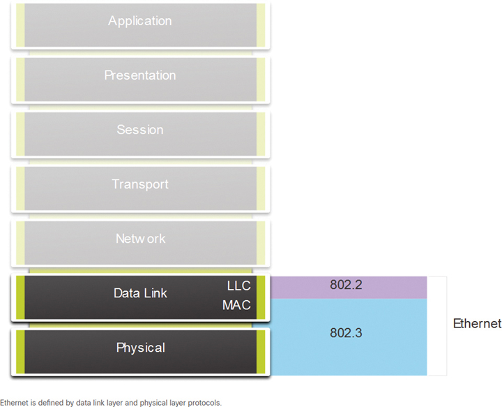
Figure 7-1 Ethernet in the OSI Model
Data Link Sublayers (7.1.2)
IEEE 802 LAN/MAN protocols, including Ethernet, use the two sublayers of the data link layer to operate: the Logical Link Control (LLC) and the Media Access Control (MAC) layers (see Figure 7-2).

Figure 7-2 IEEE Ethernet Standards in the OSI Model
Recall that the LLC and MAC sublayers have the following roles in the data link layer:
LLC sublayer: This IEEE 802.2 sublayer communicates between the networking software at the upper layers and the device hardware at the lower layers. It places information in the frame to identify which network layer protocol is being used for the frame. This information allows multiple Layer 3 protocols, such as IPv4 and IPv6, to use the same network interface and media.
MAC sublayer: This sublayer (specified in IEEE 802.3, 802.11, and 802.15), which is implemented in hardware, is responsible for data encapsulation and media access control. It provides data link layer addressing and is integrated with various physical layer technologies.
MAC Sublayer (7.1.3)
The MAC sublayer is responsible for data encapsulation and accessing the media.
Data Encapsulation
IEEE 802.3 data encapsulation includes the following:
Ethernet frame: This is the internal structure of the Ethernet frame.
Ethernet addressing: An Ethernet frame includes both source and destination MAC addresses to deliver the Ethernet frame from Ethernet NIC to Ethernet NIC on the same LAN.
Ethernet error detection: The Ethernet frame includes a frame check sequence (FCS) trailer used for error detection.
Accessing the Media
As shown in Figure 7-3, the IEEE 802.3 MAC sublayer includes the specifications for different Ethernet communications standards over various types of media, including copper and fiber.

Figure 7-3 Details of the MAC Sublayer
Recall that legacy Ethernet using a bus topology or hubs is a shared, half-duplex medium. Ethernet over a half-duplex medium uses a contention-based access method, Carrier Sense Multiple Access/Collision Detect (CSMA/CD) to ensure that only one device is transmitting at a time. CSMA/CD allows multiple devices to share the same half-duplex medium and detects a collision when more than one device attempts to transmit simultaneously. It also provides a back-off algorithm for retransmission.
Ethernet LANs today use switches that operate in full-duplex. Full-duplex communications with Ethernet switches do not require access control through CSMA/CD.
Ethernet Frame Fields (7.1.4)
The minimum Ethernet frame size is 64 bytes, and the expected maximum is 1518 bytes. The frame size might be larger than that if additional requirements are included, such as VLAN tagging. (VLAN tagging is beyond the scope of this book.) The frame includes all bytes from the destination MAC address field through the FCS field. The Preamble field is not included when describing the size of a frame.
Any frame less than 64 bytes in length is considered a collision fragment or runt frame and is automatically discarded by receiving stations. Frames with more than 1500 bytes of data are considered jumbo frames or baby giant frames.
If the size of a transmitted frame is less than the minimum or greater than the maximum, the receiving device drops the frame. Dropped frames are likely to result from collisions or other unwanted signals. They are considered invalid. Jumbo frames are supported by most Fast Ethernet and Gigabit Ethernet switches and NICs.
Figure 7-4 shows the fields in the Ethernet frame.

Figure 7-4 Ethernet Frame Structure and Field Size
Table 7-1 provides more information about the function of each field.
Table 7-1 Ethernet Frame Fields Detail
Field |
Description |
Preamble and Start Frame Delimiter fields |
The preamble (7 bytes) and start frame delimiter (SFD), also called the start of frame (1 byte), fields are used for synchronization between the sending and receiving devices. These first 8 bytes of the frame are used to get the attention of the receiving nodes. Essentially, the first few bytes tell the receivers to get ready to receive a new frame. |
Destination MAC Address field |
This 6-byte field is the identifier for the intended recipient. Recall that Layer 2 uses this address to assist devices in determining if a frame is addressed to them. The address in a frame is compared to the MAC address in a device. If there is a match, the device accepts the frame. It can be a unicast, multicast, or broadcast address. |
Source MAC Address field |
This 6-byte field identifies the originating NIC or interface of the frame. |
Type/Length field |
This 2-byte field identifies the upper-layer protocol encapsulated in the Ethernet frame. Common values are, in hexadecimal, 0x800 for IPv4, 0x86DD for IPv6, and 0x806 for ARP. Note: You may also see this field referred to as EtherType, Type, or Length. |
Data field |
This field (which can range from 46 to 1500 bytes) contains the encapsulated data from a higher layer, which is a generic Layer 3 PDU or, more commonly, an IPv4 packet. All frames must be at least 64 bytes long. If a small packet is encapsulated, additional bits called a pad are used to increase the size of the frame to this minimum size. |
Frame Check Sequence field |
The frame check sequence (FCS) field (4 bytes) is used to detect errors in a frame. It uses a cyclic redundancy check (CRC). The sending device includes the results of a CRC in the FCS field of the frame. The receiving device receives the frame and generates a CRC to look for errors. If the calculations match, no error occurred. Calculations that do not match indicate that the data has changed; in such a case, the frame is dropped. A change in the data could be the result of a disruption of the electrical signals that represent the bits. |
Check Your Understanding—Ethernet Switching (7.1.5)

Refer to the online course to complete this activity.
Lab—Use Wireshark to Examine Ethernet Frames (7.1.6)
In this lab, you will complete the following objectives:
Part 1: Examine the Header Fields in an Ethernet II Frame
Part 2: Use Wireshark to Capture and Analyze Ethernet Frames
Ethernet MAC Address (7.2)
Ethernet technology relies on MAC addresses to function. MAC addresses are used to identify the frame source and destination.
MAC Address and Hexadecimal (7.2.1)
As discussed in detail in Chapter 5, “Number Systems,” in networking, IPv4 addresses are represented using the decimal (base 10) number system and the binary (base 2) number system. IPv6 addresses and Ethernet addresses are represented using the hexadecimal (base 16) number system. To understand hexadecimal, you must first be very familiar with binary and decimal.
The hexadecimal numbering system uses the numbers 0 to 9 and the letters A to F.
An Ethernet MAC address consists of a 48-bit binary value. Hexadecimal is used to identify an Ethernet address because a single hexadecimal digit represents 4 binary bits. Therefore, a 48-bit Ethernet MAC address can be expressed using only 12 hexadecimal values.
Figure 7-5 compares the equivalent decimal and hexadecimal values for binary 0000 to 1111.

Figure 7-5 Decimal to Binary to Hexadecimal Conversion
Given that 8 bits (1 byte) is a common binary grouping, binary 00000000 to 11111111 can be represented in hexadecimal as the range 00 to FF, as shown in the Figure 7-6.
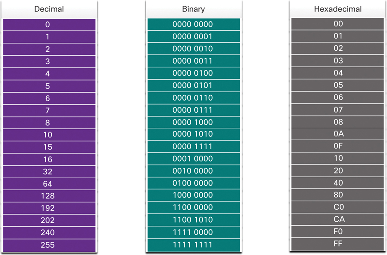
Figure 7-6 Selected Examples of Decimal to Binary to Hexadecimal Conversions
When using hexadecimal, leading zeros are always displayed to complete the 8-bit representation. For example, in Figure 7-6, the binary value 0000 1010 is shown to be 0A in hexadecimal.
Hexadecimal numbers are often represented by a value preceded by 0x (for example, 0x73) to distinguish between decimal and hexadecimal values in documentation.
Hexadecimal may also be represented using a subscript 16 or by using the hex number followed by an H (for example, 73H).
You might have to convert between decimal and hexadecimal values. If such conversions are required, convert the decimal or hexadecimal value to binary and then to convert the binary value to either decimal or hexadecimal as appropriate. See Chapter 5 for more information.
Ethernet MAC Address (7.2.2)
In an Ethernet LAN, every network device is connected to the same shared medium. The MAC address is used to identify the physical source and destination devices (NICs) on the local network segment. MAC addressing provides a method for device identification at the data link layer of the OSI model.
An Ethernet MAC address is a 48-bit address expressed using 12 hexadecimal digits, as shown in Figure 7-7. Because 1 byte equals 8 bits, we can also say that a MAC address is 6 bytes in length.

Figure 7-7 Ethernet MAC Address in Bits, Hextets, and Bytes
All MAC addresses must be unique to the Ethernet device or Ethernet interface. To ensure uniqueness, every vendor that sells Ethernet devices must register with the IEEE to obtain a unique 6-digit hexadecimal (that is, 24-bit or 3-byte) code called an organizationally unique identifier (OUI).
When a vendor assigns a MAC address to a device or to an Ethernet interface, the vendor must do as follows:
Use its assigned OUI as the first 6 hexadecimal digits.
Assign a unique value in the last 6 hexadecimal digits.
Therefore, an Ethernet MAC address consists of a 6-digit hexadecimal vendor OUI code followed by a 6-digit hexadecimal vendor-assigned value, as shown in Figure 7-8.

Figure 7-8 The Ethernet MAC Address Structure
For example, say that Cisco needs to assign a unique MAC address to a new device, and the IEEE has assigned Cisco the OUI 00-60-2F. Cisco would configure the device with a unique vendor code such as 3A-07-BC. Therefore, the Ethernet MAC address of that device would be 00-60-2F-3A-07-BC.
It is the responsibility of a vendor to ensure that no two of its devices are assigned the same MAC address. However, it is possible for duplicate MAC addresses to exist because of mistakes made during manufacturing, mistakes made in some virtual machine implementation methods, or modifications made using one of several software tools. In such a case, it is necessary to modify the MAC address with a new NIC or make modifications by using software.
Frame Processing (7.2.3)
Sometimes a MAC address is referred to as a burned-in address (BIA) because the address is hard coded into read-only memory (ROM) on the NIC. This means that the address is permanently encoded into the ROM chip.
Note
With modern PC operating systems and NICs, it is possible to change the MAC address in software. This is useful when attempting to gain access to a network that filters based on BIA. Consequently, filtering or controlling traffic based on the MAC address is no longer as secure as it once was.
When the computer boots up, the NIC copies its MAC address from ROM into RAM. When a device is forwarding a message to an Ethernet network, as shown in Figure 7-9, the Ethernet header includes the following:
Source MAC address: This is the MAC address of the source device NIC.
Destination MAC address: This is the MAC address of the destination device NIC.
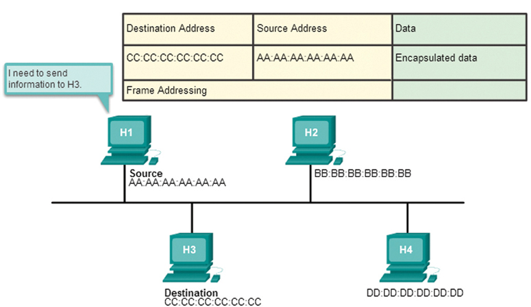
Figure 7-9 The Source Prepares a Frame to Send to the Destination
When a NIC receives an Ethernet frame, it examines the destination MAC address to see if it matches the physical MAC address that is stored in RAM. If there is no match, the device discards the frame. In Figure 7-10, H2 and H4 discard the frame. The MAC address matches for H4, so H4 passes the frame up the OSI layers, where the de-encapsulation process takes place.

Figure 7-10 All Devices Receive the Frame, but Only the Destination Processes It
Note
Ethernet NICs also accept frames if the destination MAC address is a broadcast or a multicast group of which the host is a member.
Any device that is the source or destination of an Ethernet frame will have an Ethernet NIC and, therefore, a MAC address. This includes workstations, servers, printers, mobile devices, and routers.
Unicast MAC Address (7.2.4)
In Ethernet, different MAC addresses are used for Layer 2 unicast, broadcast, and multicast communications.
A unicast MAC address is a unique address that is used when a frame is sent from a single transmitting device to a single destination device.
In Figure 7-11, the destination MAC address and the destination IP address are both unicast.

Figure 7-11 Unicast Frame Transmission
A host with IPv4 address 192.168.1.5 (source) requests a web page from the server at IPv4 unicast address 192.168.1.200. For a unicast packet to be sent and received, a destination IP address must be in the IP packet header. A corresponding destination MAC address must also be present in the Ethernet frame header. The IP address and MAC address combine to deliver data to one specific destination host.
The process that a source host uses to determine the destination MAC address associated with an IPv4 address is known as Address Resolution Protocol (ARP). The process that a source host uses to determine the destination MAC address associated with an IPv6 address is known as Neighbor Discovery (ND).
Note
The source MAC address must always be a unicast address.
Broadcast MAC Address (7.2.5)
An Ethernet broadcast frame is received and processed by every device on an Ethernet LAN. The features of an Ethernet broadcast are as follows:
It has the destination MAC address FF-FF-FF-FF-FF-FF in hexadecimal (or 48 1s in binary).
It is flooded out all Ethernet switch ports except the incoming port.
It is not forwarded by a router.
If the encapsulated data is an IPv4 broadcast packet, this means the packet contains a destination IPv4 address that has all 1s in the host portion. This numbering in the address means that all hosts on that local network (broadcast domain) receive and process the packet.
In Figure 7-12, the destination MAC address and destination IP address are both broadcast addresses.
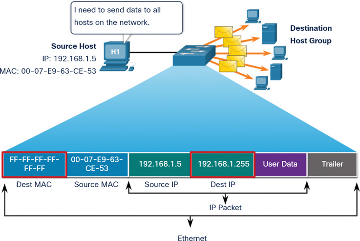
Figure 7-12 Broadcast Frame Transmission
The source host sends an IPv4 broadcast packet to all devices on its network. The IPv4 destination address is a broadcast address, 192.168.1.255. When the IPv4 broadcast packet is encapsulated in the Ethernet frame, the destination MAC address is the broadcast MAC address FF-FF-FF-FF-FF-FF in hexadecimal (or 48 1s in binary).
DHCP for IPv4 is an example of a protocol that uses Ethernet and IPv4 broadcast addresses. However, not all Ethernet broadcasts carry IPv4 broadcast packets. For example, ARP requests do not use IPv4, but the ARP message is sent as an Ethernet broadcast.
Multicast MAC Address (7.2.6)
An Ethernet multicast frame is received and processed by a group of devices on the Ethernet LAN that belong to the same multicast group. The features of an Ethernet multicast frame are as follows:
It has destination MAC address 01-00-5E when the encapsulated data is an IPv4 multicast packet and destination MAC address 33-33 when the encapsulated data is an IPv6 multicast packet.
There are other reserved multicast destination MAC addresses for when the encapsulated data is not IP, such as Spanning Tree Protocol (STP) and Link Layer Discovery Protocol (LLDP).
It is flooded out all Ethernet switch ports except the incoming port, unless the switch is configured for multicast snooping.
It is not forwarded by a router unless the router is configured to route multicast packets.
If the encapsulated data is an IP multicast packet, the devices that belong to a multicast group are assigned a multicast group IP address. The range of IPv4 multicast addresses is 224.0.0.0 to 239.257.257.257. The range of IPv6 multicast addresses begins with ff00::/8. Because a multicast address represents a group of addresses (sometimes called a host group), it can only be used as the destination of a packet. The source is always a unicast address.
As with the unicast and broadcast addresses, a multicast IP address requires a corresponding multicast MAC address to deliver frames on a local network. The multicast MAC address is associated with, and uses addressing information from, the IPv4 or IPv6 multicast address.
In Figure 7-13, the destination MAC address and destination IP address are both multicast addresses.
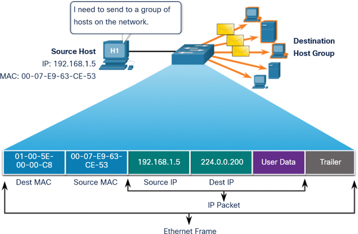
Figure 7-13 Multicast Frame Transmission
Routing protocols and other network protocols use multicast addressing. Applications such as video and imaging software may also use multicast addressing, although multicast applications are not as common.
Lab—View Network Device MAC Addresses (7.2.7)
In this lab, you will complete the following objectives:
Part 1: Set Up the Topology and Initialize Devices
Part 2: Configure Devices and Verify Connectivity
Part 3: Display, Describe, and Analyze Ethernet MAC Addresses
The MAC Address Table (7.3)
Compared to legacy Ethernet hubs, Ethernet switches improve efficiency and overall network performance. Although traditionally most LAN switches have operated at Layer 2 of the OSI model, an increasing number of Layer 3 switches are now being implemented. This section focuses on Layer 2 switches. Layer 3 switches are beyond the scope of this book.
Switch Fundamentals (7.3.1)
Now that you know all about Ethernet MAC addresses, it is time to talk about how a switch uses these addresses to forward (or discard) frames to other devices on a network. If a switch just forwarded every frame it received out all ports, your network would be so congested that it would probably come to a complete halt.
A Layer 2 Ethernet switch uses Layer 2 MAC addresses to make forwarding decisions. It is completely unaware of the data (protocol) being carried in the data portion of the frame, such as an IPv4 packet, an ARP message, or an IPv6 ND packet. The switch makes its forwarding decisions based solely on the Layer 2 Ethernet MAC addresses.
An Ethernet switch examines its MAC address table to make a forwarding decision for each frame. In contrast, a legacy Ethernet hub repeats bits out all ports except the incoming port. In Figure 7-14, the four-port switch was just powered on. The table shows the MAC address table, which has not yet learned the MAC addresses for the four attached PCs.
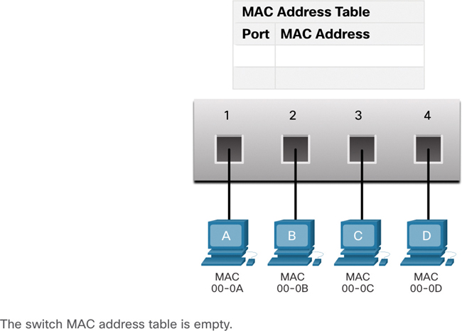
Figure 7-14 Switch Powers Up with an Empty MAC Address Table
Note
MAC addresses are shortened throughout this section for demonstration purposes.
Note
The MAC address table is sometimes referred to as a content-addressable memory (CAM) table. While the term CAM table is fairly common, for the purposes of this course, we refer to it as a MAC address table.
Switch Learning and Forwarding (7.3.2)
A switch dynamically builds its MAC address table by examining the source MAC addresses of the frames received on a port. The switch forwards frames by searching for a match between the destination MAC address in a frame and an entry in the MAC address table.
Examine the Source MAC Address
Every frame that enters a switch is checked for new information to learn. It does this by examining the source MAC address of the frame and the port number where the frame entered the switch. If the source MAC address does not exist, it is added to the table, along with the incoming port number. If the source MAC address does exist, the switch updates the refresh timer for that entry. By default, most Ethernet switches keep an entry in the table for 5 minutes.
In Figure 7-15, for example, PC-A is sending an Ethernet frame to PC-D. The table shows that the switch adds the MAC address for PC-A to the MAC address table.

Figure 7-15 Switch Learns the MAC Address for PC-A
Note
If the source MAC address exists in the table but on a different port, the switch treats this as a new entry. The entry is replaced using the same MAC address but with the more current port number.
Find the Destination MAC Address
If the destination MAC address is a unicast address, the switch looks for a match between the destination MAC address of the frame and an entry in its MAC address table. If the destination MAC address is in the table, the switch forwards the frame out the specified port. If the destination MAC address is not in the table, the switch forwards the frame out all ports except the incoming port. This is called an unknown unicast.
As shown in Figure 7-16, the switch does not have the destination MAC address in its table for PC-D, so it sends the frame out all ports except port 1.

Figure 7-16 Switch Forwards the Frame Out All Other Ports
Note
If the destination MAC address is a broadcast or a multicast address, the frame is flooded out all ports except the incoming port.
Filtering Frames (7.3.3)
As a switch receives frames from different devices, it is able to populate its MAC address table by examining the source MAC address of every frame. When the MAC address table of the switch contains the destination MAC address, the switch is able to filter the frame and forward out a single port.
In Figure 7-17, PC-D is replying to PC-A. The switch sees the MAC address of PC-D in the incoming frame on port 4. The switch then puts the MAC address of PC-D into the MAC address table associated with port 4.

Figure 7-17 Switch Learns the MAC Address for PC-D
Next, because the switch has the destination MAC address for PC-A in the MAC address table, it sends the frame only out port 1, as shown in Figure 7-18.

Figure 7-18 Switch Forwards the Frame Out the Port Belonging to PC-A
Next, PC-A sends another frame to PC-D, as shown in Figure 7-19. The MAC address table already contains the MAC address for PC-A; therefore, the 5-minute refresh timer for that entry is reset. Next, because the switch table contains the destination MAC address for PC-D, it sends the frame out only port 4.

Figure 7-19 Switch Forwards the Frame Out the Port Belonging to PC-D
Video—MAC Address Tables on Connected Switches (7.3.4)

A switch can have multiple MAC addresses associated with a single port. This is common when the switch is connected to another switch. The switch will have a separate MAC address table entry for each frame received with a different source MAC address.
Refer to the online course to view this video.
Video—Sending the Frame to the Default Gateway (7.3.5)
When a device has an IP address that is on a remote network, the Ethernet frame cannot be sent directly to the destination device. Instead, the Ethernet frame is sent to the MAC address of the default gateway, the router.
Refer to the online course to view this video.
Activity—Switch It! (7.3.6)
Use this activity to check your understanding of how a switch learns and forwards frames.
Refer to the online course to complete this activity.
Lab—View the Switch MAC Address Table (7.3.7)
In this lab, you will complete the following objectives:
Part 1: Build and Configure the Network
Part 2: Examine the Switch MAC Address Table
Switch Speeds and Forwarding Methods (7.4)
Switches may have the capability to implement various forwarding methods to increase performance in a network.
Frame Forwarding Methods on Cisco Switches (7.4.1)
As you learned in the previous section, a switch uses its MAC address table to determine which port to use to forward frames. With Cisco switches, there are actually two frame forwarding methods, and there are good reasons to use one instead of the other, depending on the situation.
Switches use one of the following forwarding methods for switching data between network ports:
Store-and-forward switching: With this frame forwarding method, the switch receives the entire frame and computes the CRC. The switch uses a mathematical formula, based on the number of bits (1s) in the frame, to determine whether the received frame has an error. If the CRC is valid, the switch looks up the destination address, which determines the outgoing interface. Then the frame is forwarded out the correct port.
Cut-through switching: With this frame forwarding method, the switch forwards the frame before it is entirely received. At a minimum, the destination address of the frame must be read before the frame can be forwarded.
A big advantage of store-and-forward switching is that the switch determines whether a frame has errors before propagating the frame. When an error is detected in a frame, the switch discards the frame. Discarding frames with errors reduces the amount of bandwidth consumed by corrupt data. Store-and-forward switching is required for quality of service (QoS) analysis on converged networks where frame classification for traffic prioritization is necessary. For example, voice over IP (VoIP) data streams need to have priority over web-browsing traffic.
Figure 7-20 shows the store-and-forward process.
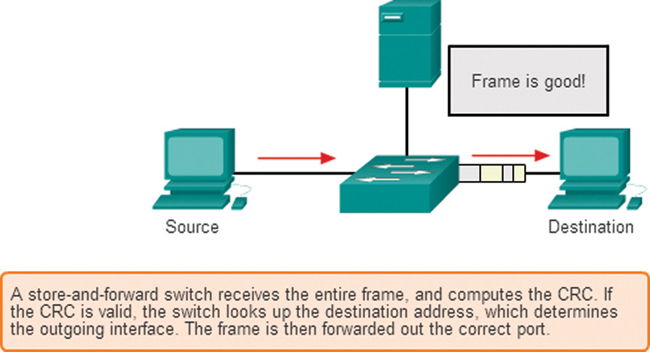
Figure 7-20 Store-and-Forward Switching
Cut-Through Switching (7.4.2)
In cut-through switching, the switch acts on the data as soon as it is received, even if the transmission is not complete. The switch buffers just enough of the frame to read the destination MAC address so that it can determine which port to use to forward the data. The destination MAC address is located in the first 6 bytes of the frame, following the preamble. The switch looks up the destination MAC address in its switching table, determines the outgoing interface port, and forwards the frame on to its destination through the designated switch port. The switch does not perform any error checking on the frame.
Figure 7-21 shows the cut-through switching process.

Figure 7-21 Cut-Through Switching
There are two variants of cut-through switching:
Fast-forward switching: Fast-forward switching offers the lowest level of latency. With fast-forward switching, the switch immediately forwards a packet after reading the destination address. Because with fast-forward switching the switch starts forwarding before the entire packet has been received, there may be times when packets are relayed with errors. This occurs infrequently, and the destination NIC discards the faulty packet upon receipt. In fast-forward mode, latency is measured from the first bit received to the first bit transmitted. Fast-forward switching is the typical cut-through method of switching.
Fragment-free switching: In fragment-free switching, the switch stores the first 64 bytes of the frame before forwarding. Fragment-free switching can be viewed as a compromise between store-and-forward switching and fast-forward switching. The reason the switch stores only the first 64 bytes of the frame is that most network errors and collisions occur during the first 64 bytes. Fragment-free switching tries to enhance fast-forward switching by performing a small error check on the first 64 bytes of the frame to ensure that a collision has not occurred before forwarding the frame. Fragment-free switching is a compromise between the high latency and high integrity of store-and-forward switching and the low latency and reduced integrity of fast-forward switching.
Some switches are configured to perform cut-through switching on a per-port basis until a user-defined error threshold is reached, and then they automatically change to store-and-forward. When the error rate falls below the threshold, the port automatically changes back to cut-through switching.
Memory Buffering on Switches (7.4.3)
An Ethernet switch may use a buffering technique to store frames before forwarding them. Buffering may also be used when the destination port is busy due to congestion. The switch stores the frame until it can be transmitted.
As shown in Table 7-2, there are two methods of memory buffering.
Table 7-2 Memory Buffering Methods
Method |
Description |
Port-based memory buffering |
Frames are stored in queues that are linked to specific incoming and outgoing ports. |
A frame is transmitted to the outgoing port only when all the frames ahead in the queue have been successfully transmitted. |
|
It is possible for a single frame to delay the transmission of all the frames in memory because a destination port is busy. This delay occurs even if the other frames could be transmitted to open destination ports. |
|
Shared memory buffering |
All frames are deposited into a common memory buffer shared by all switch ports, and the amount of buffer memory required by a port is dynamically allocated. |
The frames in the buffer are dynamically linked to the destination port, enabling a packet to be received on one port and then transmitted on another port, without moving it to a different queue. |
Shared memory buffering results in the ability to store larger frames with potentially fewer dropped frames. This is important with asymmetric switching, which allows for different data rates on different ports, such as when connecting a server to a 10 Gbps switch port and PCs to 1 Gbps ports.
Duplex and Speed Settings (7.4.4)
Two of the most basic settings on a switch are the bandwidth (sometimes referred to as speed) and duplex settings for each individual switch port. It is critical that the duplex and bandwidth settings match between the switch port and the connected devices, such as computers or other switches.
Two types of duplex settings are used for communications on an Ethernet network:
Full-duplex: Both ends of the connection can send and receive simultaneously.
Half-duplex: Only one end of the connection can send at a time.
Autonegotiation is an optional function on most Ethernet switches and NICs. It enables two devices to automatically negotiate the best speed and duplex capabilities. Full-duplex is chosen if both devices have the capability, along with their highest common bandwidth.
In Figure 7-22, the Ethernet NIC for PC-A can operate in full-duplex or half-duplex and at 10 Mbps or 100 Mbps. PC-A is connected to switch S1 on port 1, which can operate in full-duplex or half-duplex and at 10 Mbps, 100 Mbps, or 1000 Mbps (1 Gbps). If both devices are using autonegotiation, the operating mode is full-duplex, at 100 Mbps.
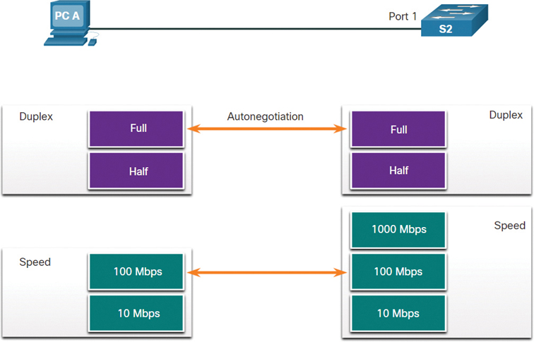
Figure 7-22 Duplex and Speed Settings
Note
Most Cisco switches and Ethernet NICs default to autonegotiation for speed and duplexing. Gigabit Ethernet ports operate only in full-duplex.
Duplex mismatch is one of the most common causes of performance issues on 10/100 Mbps Ethernet links. It occurs when one port on the link operates at half-duplex while the other port operates at full-duplex, as shown in Figure 7-23. In this scenario, S2 will continually experience collisions because S1 keeps sending frames any time it has something to send.

Figure 7-23 Duplex Mismatch
Duplex mismatch occurs when one or both ports on a link are reset, and the autonegotiation process does not result in the two link partners having the same configuration. It also can occur when users reconfigure one side of a link and forget to reconfigure the other. Both sides of a link should have autonegotiation on, or both sides should have it off. Best practice is to configure both Ethernet switch ports as full-duplex.
Auto-MDIX (7.4.5)
At one time, connections between devices required the use of either a crossover cable or a straight-through cable. The type of cable required depended on the type of interconnecting devices. For example, Figure 7-24 identifies the correct cable types required to interconnect a switch to a switch, a switch to a router, a switch to a host, or a router to a host. A crossover cable is used for connecting like devices, and a straight-through cable is used for connecting unlike devices.

Figure 7-24 Cable Types
Note
A direct connection between a router and a host requires a crossover connection.
Most switch devices now support the automatic medium-dependent interface crossover (auto-MDIX) feature. When this feature is enabled, the switch automatically detects the type of cable attached to the port and configures the interfaces accordingly. Therefore, you can use either a crossover cable or a straight-through cable for connections to a copper 10/100/1000 port on a switch, regardless of the type of device on the other end of the connection.
The auto-MDIX feature is enabled by default on switches running Cisco IOS Release 12.2(18)SE or later. However, the feature can be disabled. For this reason, you should always use the correct cable type and should not rely on the auto-MDIX feature. Auto-MDIX can be re-enabled using the mdix auto interface configuration command.
Check Your Understanding—Switch Speeds and Forwarding Methods (7.4.6)
Refer to the online course to complete this activity.
Summary (7.5)
The following is a summary of the topics in the chapter and their corresponding online modules.
Ethernet Frame
Ethernet operates at the data link layer and the physical layer. Ethernet standards define both the Layer 2 protocols and the Layer 1 technologies. Ethernet operates at the LLC and MAC sublayers of the data link layer. Data encapsulation includes the following: Ethernet frame, Ethernet addressing, and Ethernet error detection. Ethernet LANs use switches that operate in full-duplex. The Ethernet frame fields are Preamble and Start Frame Delimiter, Destination MAC Address, Source MAC Address, EtherType, Data, and FCS.
Ethernet MAC Address
The binary number system uses the digits 0 and 1. Decimal uses 0 through 9. Hexadecimal uses 0 through 9 and the letters A through F. The MAC address is used to identify the physical source and destination devices (NICs) on the local network segment. MAC addressing provides a method for device identification at the data link layer of the OSI model. An Ethernet MAC address is a 48-bit address expressed using 12 hexadecimal digits, or 6 bytes. An Ethernet MAC address consists of a 6-digit hexadecimal vendor OUI code followed by a 6-digit hexadecimal vendor-assigned value. When a device is forwarding a message to an Ethernet network, the Ethernet header includes the source and destination MAC addresses. In Ethernet, different MAC addresses are used for Layer 2 unicast, broadcast, and multicast communications.
The MAC Address Table
A Layer 2 Ethernet switch makes forwarding decisions based solely on Layer 2 Ethernet MAC addresses. The switch dynamically builds its MAC address table by examining the source MAC addresses of the frames received on a port. The switch forwards frames by searching for a match between the destination MAC address in the frame and an entry in the MAC address table. As a switch receives frames from different devices, it is able to populate its MAC address table by examining the source MAC address of each frame. When the MAC address table of the switch contains the destination MAC address, the switch is able to filter the frame and forward it out a single port.
Switch Speeds and Forwarding Methods
Switches use one of two forwarding methods for switching data between network ports: store-and-forward switching or cut-through switching. Two variants of cut-through switching are fast-forward and fragment-free switching. Two methods of memory buffering are port-based memory buffering and shared memory buffering. Two types of duplex settings are used for communications on an Ethernet network: full-duplex and half-duplex. Autonegotiation is an optional function on most Ethernet switches and NICs. It enables two devices to automatically negotiate the best speed and duplex capabilities. Full-duplex is chosen if both devices have the capability, and their highest common bandwidth is chosen. Most switch devices now support the automatic medium-dependent interface crossover (auto-MDIX) feature. When this feature is enabled, the switch automatically detects the type of cable attached to the port and configures the interfaces accordingly.
Practice
The following activities provide practice with the topics introduced in this chapter. The lab is available in the companion Introduction to Networks Labs & Study Guide (CCNAv7) (ISBN 9780136634454). The Packet Tracer activity instructions are also provided in the Labs & Study Guide. The PKA files are available in the online course.
Labs
Lab 7.1.6: Use Wireshark to Examine Ethernet Frames
Lab 7.2.7: View Network Device MAC Addresses
Lab 7.3.7: View the Switch MAC Address Table
Check Your Understanding Questions
Complete all the review questions listed here to test your understanding of the topics and concepts in this chapter. The appendix “Answers to ‘Check Your Understanding’ Questions” lists the answers.
1. Which network device makes forwarding decisions based only on the destination MAC address that is contained in a frame?
repeater
hub
Layer 2 switch
router
2. For which network device is the primary function to send data to a specific destination based on the information found in the MAC address table?
hub
router
Layer 2 switch
modem
3. What does the LLC sublayer do?
It performs data encapsulation.
It communicates with upper protocol layers.
It is responsible for media access control.
It adds a header and trailer to a packet to form an OSI Layer 2 PDU.
4. Which statement is true about MAC addresses?
MAC addresses are implemented by software.
A NIC needs a MAC address only if it is connected to a WAN.
The first 3 bytes are used by the vendor-assigned OUI.
The ISO is responsible for MAC address regulations.
5. What happens to a runt frame received by a Cisco Ethernet switch?
The frame is dropped.
The frame is returned to the originating network device.
The frame is broadcast to all other devices on the same network.
The frame is sent to the default gateway.
6. What are the minimum and maximum sizes of an Ethernet frame? (Choose two.)
56 bytes
64 bytes
128 bytes
1024 bytes
1518 bytes
7. What addressing information does a switch record in order to build its MAC address table?
the destination Layer 3 addresses of incoming packets
the destination Layer 2 addresses of outgoing frames
the source Layer 3 addresses of outgoing frames
the source Layer 2 addresses of incoming frames
8. Which two characteristics describe Ethernet technology? (Choose two.)
It is supported by IEEE 802.3 standards.
It is supported by IEEE 802.5 standards.
It typically uses an average of 16 Mbps for data transfer.
It uses unique MAC addresses to ensure that data is sent to and processed by the appropriate destination.
It uses a ring topology.
9. What statement describes MAC addresses?
They are globally unique.
They are routable only within the private network.
They are added as part of a Layer 3 PDU.
They have 32-bit binary values.
10. What is the special value assigned to the first 24 bits of a multicast MAC address?
01-5E-00
FF-00-5E
FF-FF-FF
01-00-5E
11. What will a host on an Ethernet network do if it receives a frame with a destination MAC address that does not match its own MAC address?
It will discard the frame.
It will forward the frame to the next host.
It will remove the frame from the media.
It will strip off the data link frame to check the destination IP address.
12. What is auto-MDIX?
a type of Cisco switch
an Ethernet connector type
a feature that automatically determines speed and duplex
a feature that detects Ethernet cable type
13. Which two functions or operations are performed by the MAC sublayer? (Choose two.)
It is responsible for media access control.
It performs the function for NIC driver software.
It adds a header and trailer to form an OSI Layer 2 PDU.
It handles communication between upper and lower layers.
It adds control information to the network protocol header.
14. What type of address is 01-00-5E-0A-00-02?
an address that reaches every host inside a local subnet
an address that reaches one specific host
an address that reaches every host in the network
an address that reaches a specific group of hosts