Chapter 17
Build a Small Network
Objectives
Upon completion of this chapter, you will be able to answer the following questions:
What devices are used in a small network?
What protocols and applications are used in a small network?
How does a small network serve as the basis of larger networks?
How do you use the output of the ping and tracert commands to verify connectivity and establish relative network performance?
How do you use host and IOS commands to acquire information about the devices in a network?
What are common network troubleshooting methodologies?
How do you troubleshoot issues with devices in a network?
Key Terms
This chapter uses the following key terms. You can find the definitions in the glossary at the end of the book.
Introduction (17.0)
Hooray! You have come to the final chapter in this book. You now have most of the foundational knowledge needed to set up your own network. Where do you go from here? You build a network, of course. Once you build a network, you need to verify that it is working, and you may also need to troubleshoot some common network problems. This chapter has labs and Packet Tracer activities to help you practice your new skills as a network administrator. Let’s get going!
Devices in a Small Network (17.1)
The number and type of network devices in a small network often differ from those in larger networks, but networks of all sizes must be able to provide many of the same services.
Small Network Topologies (17.1.1)
The majority of businesses are small; therefore, it is not surprising that the majority of business networks are also small.
A small network design is usually simple. Compared to a larger network, a small network has significantly fewer devices and types of devices. For instance, refer to the sample small business network shown in Figure 17-1.

Figure 17-1 Small Business Network Topology
This small network requires a router, a switch, and a wireless access point to connect wired and wireless users, an IP phone, a printer, and a server. A small network typically has a single WAN connection provided by a DSL, cable, or Ethernet connection.
A large network requires an IT department to maintain, secure, and troubleshoot network devices and to protect organizational data. Managing a small network requires many of the same skills required for managing a larger one. Small networks are managed by a local IT technician or by a contracted professional.
Device Selection for a Small Network (17.1.2)
Like large networks, small networks require planning and design to meet user requirements. Planning ensures that all requirements, cost factors, and deployment options are given due consideration.
One of the first design considerations is the type of intermediary devices to use to support the network. The following sections describe the factors that must be considered when selecting network devices.
Cost
The cost of a switch or router is determined by its capacity and features, such as the number and types of ports available and the backplane speed. Other factors that influence the cost are network management capabilities, embedded security technologies, and optional advanced switching technologies. The expense of cable runs required to connect every device on the network must also be considered. Another key element affecting cost considerations is the amount of redundancy to incorporate into the network.
Speed and Types of Ports/Interfaces
Choosing the number and type of ports on a router or switch is a critical decision. Newer computers have built-in 1 Gbps NICs. Some servers may even have 10 Gbps ports. Although it is more expensive, choosing Layer 2 devices that can accommodate increased speeds allows the network to evolve without requiring replacement of central devices.
Expandability
Networking devices are available in fixed and modular physical configurations. A fixed configuration device has a specific number and type of ports or interfaces and cannot be expanded. A modular device has expansion slots for adding new modules as requirements evolve. Switches are available with additional ports for high-speed uplinks. Routers can be used to connect different types of networks. Care must be taken to select the appropriate modules and interfaces for the specific media.
Operating System Features and Services
Network devices must have operating systems that can support the organization’s requirements, such as the following:
Layer 3 switching
Network Address Translation (NAT)
Dynamic Host Configuration Protocol (DHCP)
Security
Quality of service (QoS)
Voice over IP (VoIP)
IP Addressing for a Small Network (17.1.3)
When implementing a network, it is important to create an IP addressing scheme and use it. Every host or device in an internetwork must have a unique address.
Devices that factor into the IP addressing scheme include the following:
End-user devices, including the number of devices and the connection types (i.e., wired, wireless, remote access)
Servers and peripherals devices (for example, printers and security cameras)
Intermediary devices, including switches and access points
It is recommended that you plan, document, and maintain an IP addressing scheme based on device type. The use of a planned IP addressing scheme makes it easier to identify a type of device and to troubleshoot problems, as, for instance, when troubleshooting network traffic issues with a protocol analyzer.
For example, consider the topology of a small to medium-sized organization in Figure 17-2.
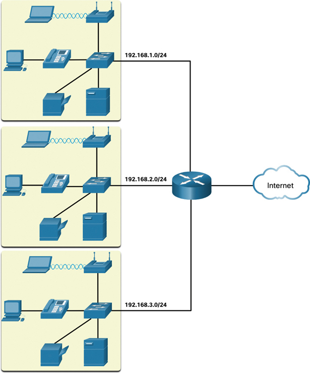
Figure 17-2 Small to Medium-Sized Organization Topology
The organization requires three user LANs (that is, 192.168.1.0/24, 192.168.2.0/24, 192.168.3.0/24). The organization has decided to implement a consistent IP addressing scheme for each 192.168.x.0/24 LAN, using the plan shown in Table 17-1.
Table 17-1 Example of a Consistent IPv4 Addressing Scheme
Device Type |
Assignable IP Address Range |
Summarized As |
Default gateway (router) |
192.168.x.1–192.168.x.2 |
192.168.x.0/30 |
Switches (max 2) |
192.168.x.5–192.168.x.6 |
192.168.x.4/30 |
Access points (max 6) |
192.168.x.9–192.168.x.14 |
192.168.x.8/29 |
Servers (max 6) |
192.168.x.17–192.168.x.22 |
192.168.x.16/29 |
Printers (max 6) |
192.168.x.25–192.168.x.30 |
192.168.x.24/29 |
IP phones (max 6) |
192.168.x.33–192.168.x.38 |
192.168.x.32/29 |
Wired devices (max 62) |
192.168.x.65–192.168.x.126 |
192.168.x.64/26 |
Wireless devices (max 62) |
192.168.x.193–192.168.x.254 |
192.168.x.192/26 |
Figure 17-3 shows an example of the 192.168.2.0/24 network devices with assigned IP addresses using the predefined IP addressing scheme.

Figure 17-3 Small Business Topology with Addressing Assigned
For instance, the default gateway IP address is 192.168.2.1/24, the switch IP address is 192.168.2.5/24, the server IP address is 192.168.2.17/24, and so on.
Notice that the assignable IP address ranges were deliberately allocated on subnetwork boundaries to simplify summarization of the group type. For instance, assume that another switch with IP address 192.168.2.6 is added to the network. To identify all switches in a network policy, the administrator could specify the summarized network address 192.168.x.4/30.
Redundancy in a Small Network (17.1.4)
An important part of network design is reliability. Even a small business often relies heavily on its network for business operation. A network failure can be very costly.
To maintain a high degree of reliability, redundancy is required in the network design. Redundancy helps to eliminate single points of failure. There are many ways to accomplish redundancy in a network. Redundancy can be accomplished by installing duplicate equipment, and it can also be accomplished by supplying duplicate network links for critical areas, as shown in Figure 17-4.
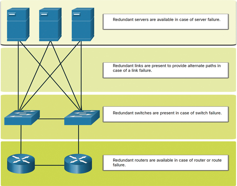
Figure 17-4 Small Network with Redundant Devices and Links
A small network typically provides a single exit point toward the internet through one or more default gateways. If the router fails, the entire network loses connectivity to the internet. For this reason, it may be advisable for a small business to pay for a second service provider as backup.
Traffic Management (17.1.5)
The goal for a good network design—even in a small network—is to enhance the productivity of the employees and minimize network downtime. The network administrator should consider the various types of traffic and their treatment in the network design.
The routers and switches in a small network should be configured to support real-time traffic, such as voice and video, in an appropriate manner relative to other data traffic. In fact, a good network design implements quality of service (QoS) to classify traffic carefully according to priority during times of congestion, as shown in Figure 17-5.

Figure 17-5 QoS Priority Queuing
Check Your Understanding—Devices in a Small Network (17.1.6)

Refer to the online course to complete this activity.
Small Network Applications and Protocols (17.2)
Along with considering the network devices in a small network, it is important to examine the applications and services that it must support.
Common Applications (17.2.1)
The previous section discusses the components of a small network, as well as some of the design considerations. These considerations are necessary when you are just setting up a network. After you have set it up, the network still needs certain types of applications and protocols in order to work.
A network is only as useful as the applications that are on it. There are two forms of software programs or processes that provide access to the network: network applications and application layer services.
Network Applications
Applications are the software programs used to communicate over a network. Some end-user applications are network aware, meaning that they implement application layer protocols and are able to communicate directly with the lower layers of the protocol stack. Email clients and web browsers are examples of this type of application.
Application Layer Services
Other programs may need the assistance of application layer services to use network resources such as file transfer or network print spooling. Although they are transparent to an employee, these services are the programs that interface with the network and prepare the data for transfer. Different types of data—whether text, graphics, or video—require different network services to ensure that they are properly prepared for processing by the functions occurring at the lower layers of the OSI model.
Each application or network service uses protocols, which define the standards and data formats to be used. Without protocols, the data network would not have a common way to format and direct data. In order to understand the function of various network services, it is necessary to become familiar with the underlying protocols that govern their operation.
On a Windows PC, you use Task Manager to view the currently running applications, processes, and services, as shown in Figure 17-6.
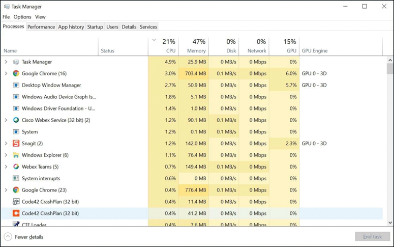
Figure 17-6 Windows Task Manager
Common Protocols (17.2.2)
Most of a technician’s work, in either a small network or a large network, is in some way involved with network protocols. Network protocols support the applications and services used by employees in a small network.
Network administrators commonly require access to network devices and servers. The two most common remote access solutions are Telnet and Secure Shell (SSH). SSH is a secure alternative to Telnet. When connected, administrators can access the SSH server device as though they were logged in locally.
SSH is used to establish a secure remote access connection between an SSH client and other SSH-enabled devices:
Network device: The network device (for example, router, switch, access point) must support SSH to provide remote access SSH server services to clients.
Server: The server (for example, web server, email server) must support remote access SSH server services to clients.
Network administrators must also support common network servers and their required related network protocols, as shown in Figure 17-7 and described in the list that follows:

Figure 17-7 Common Network Servers
Web server:
Web clients and web servers exchange web traffic by using Hypertext Transfer Protocol (HTTP).
Web clients and web servers exchange secure web communication by using Hypertext Transfer Protocol Secure (HTTPS).
Email server:
Email servers and clients use Simple Mail Transfer Protocol (SMTP) to send emails.
Email clients use Post Office Protocol (POP3) or Internet Message Access Protocol (IMAP) to retrieve email.
Recipients are specified using the user@xyz.xxx format.
FTP server:
File Transfer Protocol (FTP) allows files to be downloaded and uploaded between a client and an FTP server.
FTP Secure (FTPS) and Secure FTP (SFTP) are used for secure FTP file exchange.
DHCP server:
Clients use Dynamic Host Configuration Protocol (DHCP) to acquire an IP configuration (that is, IP address, subnet mask, default gateway and more) from a DHCP server.
DNS server:
Domain Name System (DNS) resolves a domain name to an IP address (for example, cisco.com = 72.163.4.185).
DNS provides the IP address of a website (that is, domain name) to a requesting host.
Note
A server could provide multiple network services. For instance, a server could be an email server, an FTP server, and an SSH server.
These network protocols comprise the fundamental toolset of a network professional. Each of these network protocols defines the following:
Processes on either end of a communication session
Types of messages
Syntax of messages
Meaning of informational fields
How messages are sent and the expected responses
Interaction with the next lower layer
Many companies have established a policy of using secure versions (for example, SSH, SFTP, HTTPS) of these protocols whenever possible.
Voice and Video Applications (17.2.3)
Businesses today are increasingly using IP telephony and streaming media to communicate with customers and business partners. Many organizations are enabling their employees to work remotely. Many of their users require access to corporate software and files, as well as support for voice and video applications.
A network administrator must ensure that the proper equipment is installed in the network and that the network devices are configured to ensure priority delivery.
The following are factors that a small network administrator must consider when supporting real-time applications:
Infrastructure:
The network infrastructure must support the real-time applications.
Existing devices and cabling must be tested and validated.
Newer networking products may be required.
VoIP:
VoIP devices convert analog telephone signals into digital IP packets.
Typically, VoIP is less expensive than an IP telephony solution, but the quality of communications does not meet the same standards.
Small network voice and video over IP can be solved using Skype and non-enterprise versions of Cisco WebEx.
IP telephony:
An IP phone performs voice-to-IP conversion with the use of a dedicated server for call control and signaling.
Many vendors provide small business IP telephony solutions such as the Cisco Business Edition 4000 Series products.
Real-time applications:
The network must support quality-of-service (QoS) mechanisms to minimize latency issues for real-time streaming applications.
Real-Time Transport Protocol (RTP) and Real-Time Transport Control Protocol (RTCP) are two protocols that support this requirement.
Check Your Understanding—Small Network Applications and Protocols (17.2.4)
Refer to the online course to complete this activity.
Scale to Larger Networks (17.3)
Networks support the business and must be able to grow as the business grows.
Small Network Growth (17.3.1)
If your network is for a small business, presumably, you want that business to grow, and you want your network to grow along with it. This is called scaling a network, and there are some best practices for doing this.
Growth is a natural process for many small businesses, whose networks must grow accordingly. Ideally, a network administrator has enough lead time to make intelligent decisions about growing the network in alignment with the growth of the company.
To scale a network, several elements are required:
Network documentation: Physical and logical topology
Device inventory: List of devices that use or comprise the network
Budget: Itemized IT budget, including the fiscal year equipment purchasing budget
Traffic analysis: Documentation of protocols, applications, and services and their respective traffic requirements
These elements are used to inform the decision making that accompanies the scaling of a small network.
Protocol Analysis (17.3.2)
As a network grows, it becomes important to determine how to manage network traffic. It is important to understand the type of traffic that is crossing the network as well as the current traffic flow. Several network management tools can be used for this purpose. However, a simple protocol analyzer such as Wireshark can also be used.
For instance, running Wireshark on several key hosts can reveal the types of network traffic flowing through the network. Figure 17-8 shows Wireshark protocol hierarchy statistics for a Windows host on a small network. The screen capture reveals that the host is using IPv6 and IPv4 protocols. The IPv4-specific output also reveals that the host has used DNS, SSL, HTTP, ICMP, and other protocols.

Figure 17-8 Wireshark Capture Showing Packet Statistics
To determine traffic flow patterns, it is important to do the following:
Capture traffic during peak utilization times to get a good representation of the different traffic types.
Perform the capture on different network segments and devices as some traffic will be local to a particular segment.
Information gathered by the protocol analyzer is evaluated based on the source and destination of the traffic, as well as the type of traffic being sent. This analysis can be used to make decisions on how to manage the traffic more efficiently. This can be done by reducing unnecessary traffic flows or changing flow patterns altogether by moving a server, for example.
Sometimes, simply relocating a server or service to another network segment improves network performance and accommodates the growing traffic needs. At other times, optimizing network performance requires major network redesign and intervention.
Employee Network Utilization (17.3.3)
In addition to understanding changing traffic trends, a network administrator must be aware of how network use is changing. Many operating systems provide built-in tools to display such information. For example, a Windows host provides tools such as Task Manager, Event Viewer, and Data Usage. Such tools can be used to capture “snapshots” of information such as the following:
OS and OS version
CPU utilization
RAM utilization
Drive utilization
Non-network applications
Network applications
Documenting snapshots for employees in a small network over a period of time is very useful in identifying evolving protocol requirements and associated traffic flows. A shift in resource utilization may require the network administrator to adjust network resource allocations accordingly.
The Windows 10 Data Usage tool is especially useful for determining which applications are using network services on a host. The Data Usage tool is accessed by selecting Settings > Network & Internet > Data usage > network interface (from the last 30 days).
The example in Figure 17-9 shows the applications running on a remote user’s Windows 10 host using the local Wi-Fi network connection.
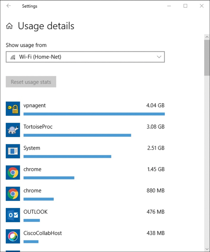
Figure 17-9 Windows 10 Usage Details for a Wi-Fi Network Connection
Check Your Understanding—Scale to Larger Networks (17.3.4)
Refer to the online course to complete this activity.
Verify Connectivity (17.4)
After a network has been implemented, a network administrator must be able to test the network connectivity to ensure that it is operating appropriately. In addition, it is a good idea for the network administrator to document the network.
Verify Connectivity with Ping (17.4.1)
Whether a network is small and new, and even if you are scaling an existing network, you will always want to be able to verify that your components are properly connected to each other and to the internet. This section discusses some utilities that you can use to ensure that a network is connected.
Using the ping command is the most effective way to quickly test Layer 3 connectivity between a source IP address and a destination IP address. This command also displays various round-trip time statistics.
Specifically, the ping command uses the Internet Control Message Protocol (ICMP) Echo Request (ICMP Type 8) and Echo Reply (ICMP Type 0) messages. The ping command is available in most operating systems, including Windows, Linux, macOS, and Cisco IOS.
On a Windows 10 host, the ping command sends four consecutive ICMP Echo Request messages and expects four consecutive ICMP Echo Reply messages from the destination.
For example, say that PC A pings PC B. As shown in Figure 17-10, the PC A Windows host sends four consecutive ICMP Echo Request messages to PC B (that is, 10.1.1.10).

Figure 17-10 PC A Pinging PC B
The destination host receives and processes the ICMP Echo Request, sometimes referred to as an ICMP Echo. As shown in Figure 17-11, PC B responds by sending four ICMP Echo Reply messages to PC A.
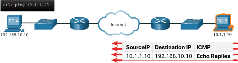
Figure 17-11 PC B Responding to PC A
As shown in the command output in Example 17-1, PC A has received Echo Reply messages from PC B, verifying the Layer 3 network connection. This output validates Layer 3 connectivity between PC A and PC B.
Example 17-1 ping Output on PC A
C:UsersPC-A> ping 10.1.1.10
Pinging 10.1.1.10 with 32 bytes of data:
Reply from 10.1.1.10: bytes=32 time=47ms TTL=51
Reply from 10.1.1.10: bytes=32 time=60ms TTL=51
Reply from 10.1.1.10: bytes=32 time=53ms TTL=51
Reply from 10.1.1.10: bytes=32 time=50ms TTL=51
Ping statistics for 10.1.1.10:
    Packets: Sent = 4, Received = 4, Lost = 0 (0% loss),
Approximate round trip times in milli-seconds:
    Minimum = 47ms, Maximum = 60ms, Average = 52ms
C:UsersPC-A>
ping command output in Cisco IOS varies from ping command output on a Windows host. For instance, the IOS ping sends five ICMP Echo messages, as shown in Example 17-2.
Example 17-2 ping Output on R1
R1# ping 10.1.1.10
Type escape sequence to abort.
Sending 5, 100-byte ICMP Echos to 10.1.1.10, timeout is 2 seconds:
!!!!!
Success rate is 100 percent (5/5), round-trip min/avg/max = 1/1/2 ms
R1#
Notice the !!!!! output characters. The IOS ping command displays one ! output character for each ICMP Echo Reply received. Table 17-2 lists the most common output characters from the ping command.
Table 17-2 IOS ping Indicators
Element |
Description |
! |
|
. |
|
U |
|
Note
Other possible ping replies include Q, M, ?, and &. However, these replies are beyond the scope of this chapter.
Extended Ping (17.4.2)
A standard ping uses the IP address of the interface closest to the destination network as the source of the ping. The source IP address of the ping 10.1.1.10 command on R1 would be that of the G0/0/0 interface (that is, 209.165.200.225), as illustrated in Figure 17-12.

Figure 17-12 R1 Pinging PC B Using the Exit Interface as the Source IPv4 Address
Cisco IOS offers an “extended” mode of the ping command. This mode enables the user to create special types of pings by adjusting parameters related to the command operation.
You enter an extended ping in privileged EXEC mode by typing ping without a destination IP address. You are then given several prompts to customize the extended ping.
Note
Press Enter to accept the indicated default values.
For example, say that you wanted to test connectivity from the R1 LAN (that is, 192.168.10.0/24) to the 10.1.1.0 LAN. This could be verified from PC A. However, an extended ping could be configured on R1 to specify a different source address.
As illustrated in Figure 17-13, the source IP address of the extended ping command on R1 could be configured to use the G0/0/1 interface IP address (that is, 192.168.10.1).

Figure 17-13 R1 Pinging PC B Using an Extended ping
Example 17-3 shows the configuration of an extended ping on R1, with the source IP address of the G0/0/1 interface (that is, 192.168.10.1).
Example 17-3 Extended ping on R1
R1# ping
Protocol [ip]:
Target IP address: 10.1.1.10
Repeat count [5]:
Datagram size [100]:
Timeout in seconds [2]:
Extended commands [n]: y
Ingress ping [n]:
Source address or interface: 192.168.10.1
DSCP Value [0]:
Type of service [0]:
Set DF bit in IP header? [no]:
Validate reply data? [no]:
Data pattern [0x0000ABCD]:
Loose, Strict, Record, Timestamp, Verbose[none]:
Sweep range of sizes [n]:
Type escape sequence to abort.
Sending 5, 100-byte ICMP Echos to 10.1.1.1, timeout is 2 seconds:
Packet sent with a source address of 192.168.10.1
!!!!!
Success rate is 100 percent (5/5), round-trip min/avg/max = 1/1/1 ms
R1#
Note
The ping ipv6 command is used for IPv6 extended pings.
Verify Connectivity with Traceroute (17.4.3)
The ping command is useful for quickly determining whether there is a Layer 3 connectivity problem. However, it does not identify where a problem is located along the path.
traceroute can help locate Layer 3 problem areas in a network. It returns a list of hops as a packet is routed through a network. It could be used to identify the point along the path where the problem can be found.
The syntax of the traceroute command varies between operating systems, as illustrated in Figure 17-14.
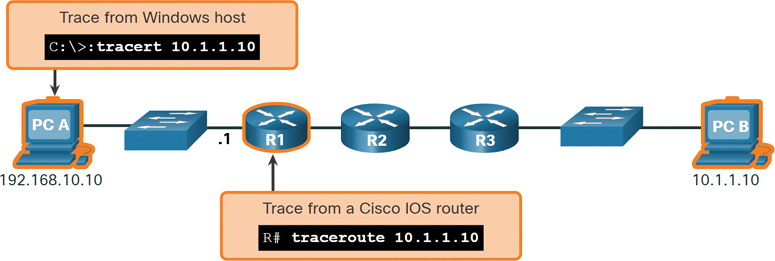
Figure 17-14 Windows and Cisco IOS Trace Commands
Example 17-4 shows the output of the tracert command on a Windows 10 host.
Example 17-4 The tracert Command on PC A
C:UsersPC-A> tracert 10.1.1.10
Tracing route to 10.1.10 over a maximum of 30 hops:
  1     2 ms     2 ms     2 ms  192.168.10.1
  2     *        *        *     Request timed out.
  3     *        *        *     Request timed out.
  4     *        *        *     Request timed out.
^C
C:UsersPC-A>
Note
Use Ctrl+C to interrupt tracert in Windows.
The only successful response in Example 17-4 was from the gateway on R1. Trace requests to the next hop timed out, as indicated by the asterisk (*), meaning that the next hop router did not respond. The timed out requests indicate that there is a failure in the internetwork beyond the LAN or that these routers have been configured to not respond to Echo Request messages used in the trace. In this example, there appears to be a problem between R1 and R2.
The output of the Cisco IOS traceroute command differs from the output of the Windows tracert command. The topology in Figure 17-15 provides an example.

Figure 17-15 Cisco IOS traceroute Command
Example 17-5 shows sample output of the traceroute command on R1. In this example, the output validates that the traceroute command could successfully reach PC B.
Example 17-5 The traceroute Command on R1
R1# traceroute 10.1.1.10
Type escape sequence to abort.
Tracing the route to 10.1.1.10
VRF info: (vrf in name/id, vrf out name/id)
  1 209.165.200.226 1 msec 0 msec 1 msec
  2 209.165.200.230 1 msec 0 msec 1 msec
  3 10.1.1.10 1 msec 0 msec
R1#
Timeouts indicate potential problems. For instance, if the 10.1.1.10 host were not available, the traceroute command would display the output shown in Example 17-6.
Example 17-6 Host Unreachable Output for the traceroute Command on R1
R1# traceroute 10.1.1.10
Type escape sequence to abort.
Tracing the route to 10.1.1.10
VRF info: (vrf in name/id, vrf out name/id)
  1 209.165.200.226 1 msec 0 msec 1 msec
  2 209.165.200.230 1 msec 0 msec 1 msec
  3  *  *  *
  4  *  *  *
  5  *
Use Ctrl+Shift+6 to interrupt a traceroute command in Cisco IOS.
Note
The Windows implementation of traceroute (tracert) sends ICMP Echo Request messages. Cisco IOS and Linux use UDP with an invalid port number. The final destination returns an ICMP port unreachable message.
Extended Traceroute (17.4.4)
Like the extended ping command, there is also an extended traceroute command. An extended traceroute command allows an administrator to adjust parameters related to the command operation. This is helpful for locating problems when troubleshooting routing loops, determining the next hop router, or determining where packets are getting dropped or denied by a router or firewall.
The Windows tracert command allows for the input of several parameters through options at the command line. However, this additional input is not guided, as it is for the extended traceroute IOS command. Example 17-7 shows the available options for the Windows tracert command.
The Cisco IOS extended traceroute option enables the user to create a special type of trace by adjusting parameters related to the command operation. Extended traceroute is entered in privileged EXEC mode by typing traceroute without a destination IP address. IOS guides you through the command options by presenting a number of prompts related to the setting of all the different parameters.
Note
Press Enter to accept the indicated default values.
Example 17-7 The Options for the tracert Command on PC A
C:UsersPC-A> tracert /?
Usage: tracert [-d] [-h maximum_hops] [-j host-list] [-w timeout]
               [-R] [-S srcaddr] [-4] [-6] target_name
Options:
    -d                 Do not resolve addresses to hostnames.
    -h maximum_hops    Maximum number of hops to search for target.
    -j host-list       Loose source route along host-list (IPv4-only).
    -w timeout         Wait timeout milliseconds for each reply.
    -R                 Trace round-trip path (IPv6-only).
    -S srcaddr         Source address to use (IPv6-only).
    -4                 Force using IPv4.
    -6                 Force using IPv6.
C:UsersPC-A>
For example, say that you want to test connectivity to PC B from the R1 LAN. Although this could be verified from PC A, an extended traceroute could be configured on R1 to specify a different source address, as shown in Figure 17-16.
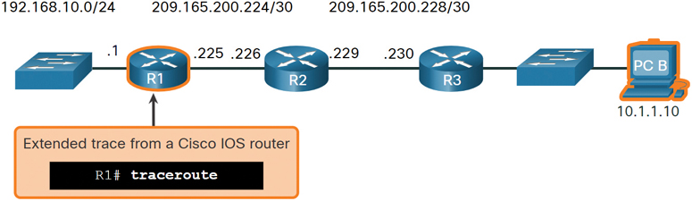
Figure 17-16 Cisco IOS Extended traceroute Command
As illustrated in Example 17-8, the source IP address of the extended traceroute command on R1 could be configured to use the R1 LAN interface IP address (that is, 192.168.10.1).
Network Baseline (17.4.5)
One of the most effective tools for monitoring and troubleshooting network performance is a network baseline. Creating an effective network performance baseline is accomplished over a period of time. Measuring performance at varying times and loads will assist in creating a better picture of overall network performance.
Example 17-8 Extended traceroute Command on R1
R1# traceroute
Protocol [ip]:
Target IP address: 10.1.1.10
Ingress traceroute [n]:
Source address: 192.168.10.1
DSCP Value [0]:
Numeric display [n]:
Timeout in seconds [3]:
Probe count [3]:
Minimum Time to Live [1]:
Maximum Time to Live [30]:
Port Number [33434]:
Loose, Strict, Record, Timestamp, Verbose[none]:
Type escape sequence to abort.
Tracing the route to 192.168.10.10
VRF info: (vrf in name/id, vrf out name/id)
  1 209.165.200.226 1 msec 1 msec 1 msec
  2 209.165.200.230 0 msec 1 msec 0 msec
  3  *
    10.1.1.10 2 msec 2 msec
R1#
The output derived from network commands contributes data to the network baseline. One method for starting a baseline is to copy and paste the results from an executed ping, traceroute, or other relevant commands into a text file. Such a text file can be timestamped with the date and saved into an archive for later retrieval and comparison with other similar files.
Among items to consider are error messages and the response times from host to host. If there is a considerable increase in response times, there may be a latency issue to address.
For example, the ping output in Example 17-9 was captured and pasted into a text file.
Example 17-9 ping on August 19, 2019, at 08:14:43
C:UsersPC-A> ping 10.1.1.10
Pinging 10.1.1.10 with 32 bytes of data:
Reply from 10.1.1.10: bytes=32 time<1ms TTL=64
Reply from 10.1.1.10: bytes=32 time<1ms TTL=64
Reply from 10.1.1.10: bytes=32 time<1ms TTL=64
Reply from 10.1.1.10: bytes=32 time<1ms TTL=64
Ping statistics for 10.1.1.10:
    Packets: Sent = 4, Received = 4, Lost = 0 (0% loss),
Approximate round trip times in milli-seconds:
    Minimum = 0ms, Maximum = 0ms, Average = 0ms
C:UsersPC-A>
Notice that the ping round-trip times are less than 1 ms.
A month later, the ping is repeated and captured, as shown in Example 17-10.
Example 17-10 ping on September 19, 2019, at 10:18:21
C:UsersPC-A> ping 10.1.1.10
Pinging 10.1.1.10 with 32 bytes of data:
Reply from 10.1.1.10: bytes=32 time=50ms TTL=64
Reply from 10.1.1.10: bytes=32 time=49ms TTL=64
Reply from 10.1.1.10: bytes=32 time=46ms TTL=64
Reply from 10.1.1.10: bytes=32 time=47ms TTL=64
Ping statistics for 10.1.1.10:
    Packets: Sent = 4, Received = 4, Lost = 0 (0% loss),
Approximate round trip times in milli-seconds:
    Minimum = 46ms, Maximum = 50ms, Average = 48ms
C:UsersPC-A>
Notice that this time the ping round-trip times are much longer, indicating a potential problem.
Corporate networks should have extensive baselines—more extensive than we can describe in this book. Professional-grade software tools are available for storing and maintaining baseline information. In this chapter, we cover a few basic techniques and discuss the purpose of baselines.
Cisco’s best practices for baseline processes can be found by searching the internet for “Baseline Process Best Practices.”
Lab—Test Network Latency with Ping and Traceroute (17.4.6)
In this lab, you will complete the following objectives:
Part 1: Use Ping to Document Network Latency
Part 2: Use Traceroute to Document Network Latency
Host and IOS Commands (17.5)
In addition to the show commands, a number of additional commands are available on hosts and network devices.
IP Configuration on a Windows Host (17.5.1)
If you have used any of the tools in the previous section to verify connectivity and found that some part of your network is not working as it should, you can use some commands to troubleshoot your devices. Host and IOS commands can help you determine if a problem is with the IP addressing of your devices, which is a common network problem.
Checking the IP addressing on host devices is a common practice in networking for verifying and troubleshooting end-to-end connectivity. In Windows 10, you can access the IP address details from the Network and Sharing Center, as shown in Figure 17-17, to quickly view four important settings: address, mask, router, and DNS.

Figure 17-17 Windows 10 Network Connection Details
However, network administrators typically view the IP addressing information on a Windows host by issuing the ipconfig command at the command line of a Windows computer, as shown in Example 17-11.
Example 17-11 Verifying the IP Configuration on a Windows Host
C:UsersPC-A> ipconfig
Windows IP Configuration
(Output omitted)
Wireless LAN adapter Wi-Fi:
   Connection-specific DNS Suffix  . :
   Link-local IPv6 Address . . . . . : fe80::a4aa:2dd1:ae2d:a75e%16
   IPv4 Address. . . . . . . . . . . : 192.168.10.10
   Subnet Mask . . . . . . . . . . . : 255.255.255.0
   Default Gateway . . . . . . . . . : 192.168.10.1
(Output omitted)
You can use the ipconfig /all command to view the MAC address, as well as a number of details regarding the Layer 3 addressing of the device, as shown in Example 17-12.
Example 17-12 Verifying Complete Addressing Information on a Windows Host
C:UsersPC-A> ipconfig /all
Windows IP Configuration
   Host Name . . . . . . . . . . . . : PC-A-00H20
   Primary Dns Suffix  . . . . . . . : cisco.com
   Node Type . . . . . . . . . . . . : Hybrid
   IP Routing Enabled. . . . . . . . : No
   WINS Proxy Enabled. . . . . . . . : No
   DNS Suffix Search List. . . . . . : cisco.com
(Output omitted)
Wireless LAN adapter Wi-Fi:
   Connection-specific DNS Suffix  . :
   Description . . . . . . . . . . . : Intel(R) Dual Band Wireless-AC 8265
   Physical Address. . . . . . . . . : F8-94-C2-E4-C5-0A
   DHCP Enabled. . . . . . . . . . . : Yes
   Autoconfiguration Enabled . . . . : Yes
   Link-local IPv6 Address . . . . . : fe80::a4aa:2dd1:ae2d:a75e%16(Preferred)
   IPv4 Address. . . . . . . . . . . : 192.168.10.10(Preferred)
   Subnet Mask . . . . . . . . . . . : 255.255.255.0
   Lease Obtained. . . . . . . . . . : August 17, 2019 1:20:17 PM
   Lease Expires . . . . . . . . . . : August 18, 2019 1:20:18 PM
   Default Gateway . . . . . . . . . : 192.168.10.1
   DHCP Server . . . . . . . . . . . : 192.168.10.1
   DHCPv6 IAID . . . . . . . . . . . : 100177090
   DHCPv6 Client DUID. . . . . . . . : 00-01-00-01-21-F3-76-75-54-E1-AD-DE-DA-9A
   DNS Servers . . . . . . . . . . . : 192.168.10.1
   NetBIOS over Tcpip. . . . . . . . : Enabled
If a host is configured as a DHCP client, the IP address configuration can be renewed by using the ipconfig /release and ipconfig /renew commands, as shown in Example 17-13.
Example 17-13 Releasing and Renewing the IP Configuration on a Windows Host
C:UsersPC-A> ipconfig /release
(Output omitted)
Wireless LAN adapter Wi-Fi:
   Connection-specific DNS Suffix  .  :
   Link-local IPv6 Address . . . . .  : fe80::a4aa:2dd1:ae2d:a75e%16
   Default Gateway . . . . . . . . .  :
(Output omitted)
C:UsersPC-A> ipconfig /renew
(Output omitted)
Wireless LAN adapter Wi-Fi:
   Connection-specific DNS Suffix  .  :
   Link-local IPv6 Address . . . . .  : fe80::a4aa:2dd1:ae2d:a75e%16
   IPv4 Address. . . . . . . . . . .  : 192.168.1.124
   Subnet Mask . . . . . . . . . . .  : 255.255.255.0
   Default Gateway . . . . . . . . .  : 192.168.1.1
(Output omitted)
C:UsersPC-A>
The DNS client service on Windows PCs also optimizes the performance of DNS name resolution by storing previously resolved names in memory. The ipconfig /displaydns command displays all the cached DNS entries on a Windows computer system, as shown in Example 17-14.
Example 17-14 Verifying the DNS Information Stored on a Windows Host
C:UsersPC-A> ipconfig /displaydns
Windows IP Configuration
(Output omitted)
    netacad.com
    ----------------------------------------
    Record Name . . . . . : netacad.com
    Record Type . . . . . : 1
    Time To Live  . . . . : 602
    Data Length . . . . . : 4
    Section . . . . . . . : Answer
    A (Host) Record . . . : 54.165.95.219
(Output omitted)
IP Configuration on a Linux Host (17.5.2)
How you verify IP settings in the GUI on a Linux machine depends on the Linux distribution (distro) and desktop interface. Figure 17-18 shows the Connection Information dialog box on the Ubuntu distro running the Gnome desktop.
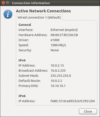
Figure 17-18 Linux Ubuntu Connection Information
On the command line, network administrators use the ifconfig command to display the status of the currently active interfaces and their IP configuration, as shown in Example 17-15.
Example 17-15 Verifying the IP Configuration on a Linux Host
[analyst@secOps ~]$ ifconfig
enp0s3     Link encap:Ethernet  HWaddr 08:00:27:b5:d6:cb
          inet addr: 10.0.2.15  Bcast:10.0.2.255  Mask: 255.255.255.0
          inet6 addr: fe80::57c6:ed95:b3c9:2951/64 Scope:Link
          UP BROADCAST RUNNING MULTICAST  MTU:1500  Metric:1
          RX packets:1332239 errors:0 dropped:0 overruns:0 frame:0
          TX packets:105910 errors:0 dropped:0 overruns:0 carrier:0
          collisions:0 txqueuelen:1000
          RX bytes:1855455014 (1.8 GB)  TX bytes:13140139 (13.1 MB)
lo: flags=73  mtu 65536
        inet 127.0.0.1  netmask 255.0.0.0
        inet6 ::1  prefixlen 128  scopeid 0x10
        loop  txqueuelen 1000  (Local Loopback)
        RX packets 0  bytes 0 (0.0 B)
        RX errors 0  dropped 0  overruns 0  frame 0
        TX packets 0  bytes 0 (0.0 B)
        TX errors 0  dropped 0 overruns 0  carrier 0  collisions 0
The Linux ip address command is used to display addresses and their properties. It can also be used to add or delete IP addresses.
Note
The output displayed may vary depending on the Linux distribution.
IP Configuration on a macOS Host (17.5.3)
In the GUI of a Mac host, open Network Preferences > Advanced to get the IP addressing information, as shown in Figure 17-19.

Figure 17-19 Configuration Information on a macOS Host
However, the ifconfig command can also be used to verify the interface IP configuration, as shown in Example 17-16.
Example 17-16 Verifying the IP Configuration on a macOS Host
MacBook-Air:~ Admin$ ifconfig en0
en0: flags=8863 mtu 1500
        ether c4:b3:01:a0:64:98
        inet6 fe80::c0f:1bf4:60b1:3adb%en0 prefixlen 64 secured scopeid 0x5
        inet 10.10.10.113 netmask 0xffffff00 broadcast 10.10.10.255
        nd6 options=201
        media: autoselect
        status: active
MacBook-Air:~ Admin$
Other useful macOS commands to verify the host IP settings include networksetup -listallnetworkservices and networksetup -getinfo <network service>. The networksetup-listallnetworkservices command is shown in Example 17-17.
Example 17-17 Verifying Other Network Configuration Information on a macOS Host
MacBook-Air:~ Admin$ networksetup -listallnetworkservices
An asterisk (*) denotes that a network service is disabled.
iPhone USB
Wi-Fi
Bluetooth PAN
Thunderbolt Bridge
MacBook-Air:~ Admin$
MacBook-Air:~ Admin$ networksetup -getinfo Wi-Fi
DHCP Configuration
IP address: 10.10.10.113
Subnet mask: 255.255.255.0
Router: 10.10.10.1
Client ID:
IPv6: Automatic
IPv6 IP address: none
IPv6 Router: none
Wi-Fi ID: c4:b3:01:a0:64:98
MacBook-Air:~ Admin$
The arp Command (17.5.4)
The arp command is executed from the Windows, Linux, or Mac command prompt. This command lists all devices currently in the ARP cache of the host, as well as each device’s IPv4 address, physical address, and the type of addressing (static/dynamic). For instance, refer to the topology in Figure 17-20.

Figure 17-20 ARP Example Topology
Example 17-18 displays the output of the arp -a command on the Windows PC-A host.
Example 17-18 The ARP Table on a Windows Host
C:UsersPC-A> arp -a
Interface: 192.168.93.175 --- 0xc
  Internet Address      Physical Address      Type
  10.0.0.2              d0-67-e5-b6-56-4b     dynamic
  10.0.0.3              78-48-59-e3-b4-01     dynamic
  10.0.0.4              00-21-b6-00-16-97     dynamic
  10.0.0.254            00-15-99-cd-38-d9     dynamic
The arp -a command displays the known IP address and MAC address binding. Notice that IP address 10.0.0.5 is not included in Example 17-18. This is because the ARP cache only displays information from devices that have been recently accessed.
To ensure that the ARP cache is populated, you can ping a device so that it has an entry in the ARP table. For instance, if PC-A pings 10.0.0.5, the ARP cache then contains an entry for that IP address.
A network administrator who wants to repopulate the cache with updated information can clear the cache by using the netsh interface ip delete arpcache command.
Note
You may need administrator access on the host to be able to use the netsh interface ip delete arpcache command.
Common show Commands Revisited (17.5.5)
In the same way that commands and utilities are used to verify a host configuration, commands can be used to verify the interfaces of intermediary devices. Cisco IOS provides commands to verify the operation of router and switch interfaces.
The Cisco IOS CLI show commands display relevant information about the configuration and operation of a device. Network technicians use show commands extensively for viewing configuration files, checking the status of device interfaces and processes, and verifying a device’s operational status. The status of nearly every process or function of a router can be displayed by using a show command.
Table 17-3 lists commonly used show commands and when to use them.
Table 17-3 Common show Commands
Command |
When It Is Useful |
show running-config |
To verify the current configuration and settings |
show interfaces |
To verify the interface status and see if there are any error messages |
show ip interface |
To verify the Layer 3 information of an interface |
show arp |
To verify the list of known hosts on the local Ethernet LANs |
show ip route |
To verify the Layer 3 routing information |
show protocols |
To verify which protocols are operational |
show version |
To verify the memory, interfaces, and licenses of the device |
Example 17-19 through 17-25 display output from each of these show commands.
Note
The output of some commands has been edited to focus on pertinent settings and to reduce content.
As shown in Example 17-19, the show running-config command verifies the current configuration and settings.
Example 17-19 The show running-config Command
R1# show running-config
(Output omitted)
!
version 15.5
service timestamps debug datetime msec
service timestamps log datetime msec
service password-encryption
!
hostname R1
!
interface GigabitEthernet0/0/0
 description Link to R2
 ip address 209.165.200.225 255.255.255.252
 negotiation auto
!
interface GigabitEthernet0/0/1
 description Link to LAN
 ip address 192.168.10.1 255.255.255.0
 negotiation auto
!
router ospf 10
 network 192.168.10.0 0.0.0.255 area 0
 network 209.165.200.224 0.0.0.3 area 0
!
banner motd ^C Authorized access only! ^C
!
line con 0
 password 7 14141B180F0B
 login
line vty 0 4
 password 7 00071A150754
 login
 transport input telnet ssh
!
end
R1#
As shown in Example 17-20, the show interfaces command verifies the interface status and displays any error messages.
Example 17-20 The show interfaces Command
R1# show interfaces
GigabitEthernet0/0/0 is up, line protocol is up
  Hardware is ISR4321-2x1GE, address is a0e0.af0d.e140 (bia a0e0.af0d.e140)
  Description: Link to R2
  Internet address is 209.165.200.225/30
  MTU 1500 bytes, BW 100000 Kbit/sec, DLY 100 usec,
     reliability 255/255, txload 1/255, rxload 1/255
  Encapsulation ARPA, loopback not set
  Keepalive not supported
  Full Duplex, 100Mbps, link type is auto, media type is RJ45
  output flow-control is off, input flow-control is off
  ARP type: ARPA, ARP Timeout 04:00:00
  Last input 00:00:01, output 00:00:21, output hang never
  Last clearing of "show interface" counters never
  Input queue: 0/375/0/0 (size/max/drops/flushes); Total output drops: 0
  Queueing strategy: fifo
  Output queue: 0/40 (size/max)
  5 minute input rate 0 bits/sec, 0 packets/sec
  5 minute output rate 0 bits/sec, 0 packets/sec
     5127 packets input, 590285 bytes, 0 no buffer
     Received 29 broadcasts (0 IP multicasts)
     0 runts, 0 giants, 0 throttles
     0 input errors, 0 CRC, 0 frame, 0 overrun, 0 ignored
     0 watchdog, 5043 multicast, 0 pause input
     1150 packets output, 153999 bytes, 0 underruns
     0 output errors, 0 collisions, 2 interface resets
     0 unknown protocol drops
     0 babbles, 0 late collision, 0 deferred
     1 lost carrier, 0 no carrier, 0 pause output
     0 output buffer failures, 0 output buffers swapped out
GigabitEthernet0/0/1 is up, line protocol is up

(Output omitted)
As shown in Example 17-21, the show ip interface command verifies the Layer 3 information of an interface.
Example 17-21 The show ip interface Command
R1# show ip interface
GigabitEthernet0/0/0 is up, line protocol is up
  Internet address is 209.165.200.225/30
  Broadcast address is 255.255.255.255
  Address determined by setup command
  MTU is 1500 bytes
  Helper address is not set
  Directed broadcast forwarding is disabled
  Multicast reserved groups joined: 224.0.0.5 224.0.0.6
  Outgoing Common access list is not set
  Outgoing access list is not set
  Inbound Common access list is not set
  Inbound  access list is not set
  Proxy ARP is enabled
  Local Proxy ARP is disabled
  Security level is default
  Split horizon is enabled
  ICMP redirects are always sent
  ICMP unreachables are always sent
  ICMP mask replies are never sent
  IP fast switching is enabled
  IP Flow switching is disabled
  IP CEF switching is enabled
  IP CEF switching turbo vector
  IP Null turbo vector
  Associated unicast routing topologies:
        Topology "base", operation state is UP
  IP multicast fast switching is enabled
  IP multicast distributed fast switching is disabled
  IP route-cache flags are Fast, CEF
  Router Discovery is disabled
  IP output packet accounting is disabled
  IP access violation accounting is disabled
  TCP/IP header compression is disabled
  RTP/IP header compression is disabled
  Probe proxy name replies are disabled
  Policy routing is disabled
  Network address translation is disabled
  BGP Policy Mapping is disabled
  Input features: MCI Check
  IPv4 WCCP Redirect outbound is disabled
  IPv4 WCCP Redirect inbound is disabled
  IPv4 WCCP Redirect exclude is disabled
GigabitEthernet0/0/1 is up, line protocol is up

(Output omitted)
As shown in Example 17-22, the show arp command 2 verifies the list of known hosts on the local Ethernet LANs.
Example 17-22 The show arp Command
R1# show arp
Protocol  Address          Age (min)  Hardware Addr   Type   Interface
Internet  192.168.10.1            -   a0e0.af0d.e141  ARPA   GigabitEthernet0/0/1
Internet  192.168.10.10          95   c07b.bcc4.a9c0  ARPA   GigabitEthernet0/0/1
Internet  209.165.200.225         -   a0e0.af0d.e140  ARPA   GigabitEthernet0/0/0
Internet  209.165.200.226       138   a03d.6fe1.9d90  ARPA   GigabitEthernet0/0/0
R1#
As shown in Example 17-23, the show ip route command verifies the Layer 3 routing information.
Example 17-23 The show ip route Command
R1# show ip route
Codes: L - local, C - connected, S - static, R - RIP, M - mobile, B - BGP
       D - EIGRP, EX - EIGRP external, O - OSPF, IA - OSPF inter area
       N1 - OSPF NSSA external type 1, N2 - OSPF NSSA external type 2
       E1 - OSPF external type 1, E2 - OSPF external type 2
       i - IS-IS, su - IS-IS summary, L1 - IS-IS level-1, L2 - IS-IS level-2
       ia - IS-IS inter area, * - candidate default, U - per-user static route
       o - ODR, P - periodic downloaded static route, H - NHRP, l - LISP
       a - application route
       + - replicated route, % - next hop override, p - overrides from PfR
Gateway of last resort is 209.165.200.226 to network 0.0.0.0
O*E2  0.0.0.0/0 [110/1] via 209.165.200.226, 02:19:50, GigabitEthernet0/0/0
      10.0.0.0/24 is subnetted, 1 subnets
O        10.1.1.0 [110/3] via 209.165.200.226, 02:05:42, GigabitEthernet0/0/0
      192.168.10.0/24 is variably subnetted, 2 subnets, 2 masks
C        192.168.10.0/24 is directly connected, GigabitEthernet0/0/1
L        192.168.10.1/32 is directly connected, GigabitEthernet0/0/1
      209.165.200.0/24 is variably subnetted, 3 subnets, 2 masks
C        209.165.200.224/30 is directly connected, GigabitEthernet0/0/0
L        209.165.200.225/32 is directly connected, GigabitEthernet0/0/0
O        209.165.200.228/30
           [110/2] via 209.165.200.226, 02:07:19, GigabitEthernet0/0/0
R1#
As shown in Example 17-24, the show protocols command verifies which protocols are operational.
Example 17-24 The show protocols Command
R1# show protocols
Global values:
  Internet Protocol routing is enabled
GigabitEthernet0/0/0 is up, line protocol is up
  Internet address is 209.165.200.225/30
GigabitEthernet0/0/1 is up, line protocol is up
  Internet address is 192.168.10.1/24
Serial0/1/0 is down, line protocol is down
Serial0/1/1 is down, line protocol is down
GigabitEthernet0 is administratively down, line protocol is down
R1#
As shown in Example 17-25, the show version command verifies the memory, interfaces, and licenses of a device.
Example 17-25 The show version Command
R1# show version
Cisco IOS XE Software, Version 03.16.08.S - Extended Support Release
Cisco IOS Software, ISR Software (X86_64_LINUX_IOSD-UNIVERSALK9-M), Version
  15.5(3)S8, RELEASE SOFTWARE (fc2)
Technical Support: http://www.cisco.com/techsupport
Copyright (c) 1986-2018 by Cisco Systems, Inc.
Compiled Wed 08-Aug-18 10:48 by mcpre

(Output omitted)

ROM: IOS-XE ROMMON
R1 uptime is 2 hours, 25 minutes
Uptime for this control processor is 2 hours, 27 minutes
System returned to ROM by reload
System image file is "bootflash:/isr4300-universalk9.03.16.08.S.155-3.S8-ext.SPA.
  bin"
Last reload reason: LocalSoft

(Output omitted)

Technology Package License Information:
-----------------------------------------------------------------
Technology     Technology-package            Technology-package
               Current       Type            Next reboot
------------------------------------------------------------------
appxk9         appxk9        RightToUse      appxk9
uck9           None          None            None
securityk9     securityk9    Permanent       securityk9
ipbase         ipbasek9      Permanent       ipbasek9
cisco ISR4321/K9 (1RU) processor with 1647778K/6147K bytes of memory.
Processor board ID FLM2044W0LT
2 Gigabit Ethernet interfaces
2 Serial interfaces
32768K bytes of non-volatile configuration memory.
4194304K bytes of physical memory.
3207167K bytes of flash memory at bootflash:.
978928K bytes of USB flash at usb0:.
Configuration register is 0x2102
R1#
The show cdp neighbors Command (17.5.6)
In addition to the commands discussed so far in this chapter, several other IOS commands are useful. Cisco Discovery Protocol (CDP) is a Cisco-proprietary protocol that runs at the data link layer. Because CDP operates at the data link layer, two or more Cisco network devices, such as routers that support different network layer protocols, can learn about each other even if Layer 3 connectivity has not been established.
When a Cisco device boots, CDP starts by default. CDP automatically discovers neighboring Cisco devices running CDP, regardless of which Layer 3 protocol or suites are running. CDP exchanges hardware and software device information with its directly connected CDP neighbors.
CDP provides the following information about each CDP neighbor device:
Device identifiers: The configured hostname of a switch, router, or other device
Address list: Up to one network layer address for each protocol supported
Port identifier: The name of the local and remote ports, in the form of an ASCII character string, such as FastEthernet 0/0
Capabilities list: Capabilities, such as whether a specific device is a Layer 2 switch or a Layer 3 switch
Platform: The hardware platform of a device (for example, a Cisco 1841 series router)
Refer to the topology in Figure 17-21 and the show cdp neighbors command output in Example 17-26.

Figure 17-21 CDP Neighbors Example Topology
Example 17-26 The show cdp neighbors Command
R3# show cdp neighbors
Capability Codes: R - Router, T - Trans Bridge, B - Source Route Bridge
                  S - Switch, H - Host, I - IGMP, r - Repeater, P - Phone,
                  D - Remote, C - CVTA, M - Two-port Mac Relay
Device ID         Local Intrfce     Holdtme    Capability  Platform  Port ID
S3                Gig 0/0/1         122               S I  WS-C2960+ Fas 0/5
Total cdp entries displayed : 1
R3#
The output in Example 17-26 shows that the R3 GigabitEthernet 0/0/1 interface is connected to the FastEthernet 0/5 interface of S3, which is a Cisco Catalyst 2960+ switch. Notice that R3 has not gathered information about S4. This is because CDP can only discover directly connected Cisco devices. S4 is not directly connected to R3 and therefore is not listed in the output.
The show cdp neighbors detail command reveals the IP address of a neighboring device. This command reveals the IP address of the neighbor regardless of whether you can ping that neighbor. This command is very helpful when two Cisco routers cannot route across their shared data link. The show cdp neighbors detail command helps determine whether one of the CDP neighbors has an IP configuration error.
As helpful as CDP is, it can also be a security risk because it can provide useful network infrastructure information to threat actors. For example, by default, many IOS versions send CDP advertisements out all enabled ports. However, best practice suggests that CDP should be enabled only on interfaces that are connecting to other infrastructure Cisco devices. CDP advertisements should be disabled on user-facing ports.
Because some IOS versions send out CDP advertisements by default, it is important to know how to disable CDP. To disable CDP globally, use the global configuration command no cdp run. To disable CDP on an interface, use the interface command no cdp enable.
The show ip interface brief Command (17.5.7)
One of the most frequently used commands is the show ip interface brief command. This command provides more abbreviated output than the show ip interface command. It provides a summary of the key information for all the network interfaces on a router.
In Example 17-27, the show ip interface brief output displays all interfaces on the router, the IP address assigned to each interface, if any, and the operational status of the interface.
Example 17-27 The show ip interface brief Command on a Router
R1# show ip interface brief
Interface             IP-Address      OK? Method Status                Protocol
GigabitEthernet0/0/0  209.165.200.225 YES manual up                    up
GigabitEthernet0/0/1  192.168.10.1    YES manual up                    up
Serial0/1/0           unassigned      NO  unset  down                  down
Serial0/1/1           unassigned      NO  unset  down                  down
GigabitEthernet0      unassigned      YES unset  administratively down down
R1#
Verify Switch Interfaces
The show ip interface brief command can be used to verify the status of the switch interfaces, as shown in Example 17-28.
Example 17-28 The show ip interface brief Command on a Switch
S1# show ip interface brief
Interface              IP-Address      OK? Method Status               Protocol
Vlanl                  192.168.254.250 YES manual up                   up
FastEthernet0/l        unassigned      YES unset  down                 down
FastEthernet0/2        unassigned      YES unset  up                   up
FastEthernet0/3        unassigned      YES unset  up                   up
The output in Example 17-28 shows that the VLAN 1 interface is assigned the IPv4 address 192.168.254.250, has been enabled, and is operational. The output also shows that the FastEthernet0/1 interface is down. This indicates that either no device is connected to the interface or the device that is connected has a network interface that is not operational. The output also shows that the FastEthernet0/2 and FastEthernet0/3 interfaces are operational. This is indicated by both the status and protocol being shown as up.
Video—The show version Command (17.5.8)

The show version command can be used to verify and troubleshoot some of the basic hardware and software components used during the boot process. Click Play to view a video from earlier in the course, which reviews an explanation of the show version command.
Refer to the online course to view this video.
Packet Tracer—Interpret show Command Output (17.5.9)

This activity is designed to reinforce the use of router show commands. In it you will examine the output of several show commands.
Troubleshooting Methodologies (17.6)
In this chapter, you have learned about some utilities and commands that you can use to help identify problem areas in a network. This is an important part of troubleshooting. There are many ways to troubleshoot a network problem. This section details a structured troubleshooting process that can help you to become a better network administrator. It also provides a few more commands to help you resolve problems. Network troubleshooting is a critical skill for any network professional.
Basic Troubleshooting Approaches (17.6.1)
Network problems can be simple or complex, and they can result from a combination of hardware, software, and connectivity issues. Technicians must be able to analyze problems and determine the cause of an error before they can resolve the network issue. This process is called troubleshooting.
A common and efficient troubleshooting methodology is based on the scientific method. Table 17-4 shows the six main steps in the troubleshooting process.
Table 17-4 Six Troubleshooting Steps
Step |
Description |
Step 1. Identify the problem. |
This is the first step in the troubleshooting process. |
Although tools can be used in this step, a conversation with the user is often very helpful. |
|
Step 2. Establish a theory of probable causes. |
After the problem is identified, try to establish a theory of probable causes. |
This step often yields more than a few probable causes to the problem. |
|
Step 3. Test the theory to determine the cause. |
Based on the probable causes, test your theories to determine which one is the cause of the problem. |
A technician often applies a quick procedure to see if it solves the problem. |
|
If a quick procedure does not correct the problem, you might need to research the problem further to establish the exact cause. |
|
Step 4. Establish a plan of action and implement the solution. |
After you have determined the exact cause of the problem, establish a plan of action to resolve the problem and implement the solution. |
Step 5. Verify the solution and implement preventive measures. |
After you have corrected the problem, verify full functionality. |
If applicable, implement preventive measures. |
|
Step 6. Document findings, actions, and outcomes. |
In the final step of the troubleshooting process, document your findings, actions, and outcomes. |
This is very important for future reference. |
To assess a problem, determine how many devices on the network are experiencing the problem. If there is a problem with one device on the network, start the troubleshooting process at that device. If there is a problem with all devices on the network, start the troubleshooting process at the device where all other devices are connected. You should develop a logical and consistent method for diagnosing network problems by eliminating one problem at a time.
Resolve or Escalate? (17.6.2)
In some situations, it might not be possible to resolve a problem immediately. A problem should be escalated when it requires a manager decision, some specific expertise, or a network access level unavailable to the troubleshooting technician.
For example, after troubleshooting, say that a technician concludes that a router module should be replaced. This problem should be escalated for manager approval. The manager may have to escalate the problem again as it may require the approval of the financial department before a new module can be purchased.
A company policy should clearly state when and how a technician should escalate a problem.
The debug Command (17.6.3)
OS processes, protocols, mechanisms, and events generate messages to communicate their status. These messages can provide valuable information when troubleshooting or verifying system operations. The IOS debug command allows an administrator to display these messages in real time for analysis. It is a very important tool for monitoring events on a Cisco IOS device.
All debug commands are entered in privileged EXEC mode. Cisco IOS allows for narrowing the output of debug to include only the relevant feature or subfeature. This is important because debugging output is assigned high priority in the CPU process, and it can render the system unusable. For this reason, use debug commands only to troubleshoot specific problems.
For example, to monitor the status of ICMP messages in a Cisco router, use debug ip icmp, as shown in Example 17-29.
Example 17-29 Using a debug Command to Monitor ICMP
R1# debug ip icmp
ICMP packet debugging is on
R1#
R1# ping 10.1.1.1
Type escape sequence to abort.
Sending 5, 100-byte ICMP Echos to 10.1.1.1, timeout is 2 seconds:
!!!!!
Success rate is 100 percent (5/5), round-trip min/avg/max = 1/1/2 ms
R1#
*Aug 20 14:18:59.605: ICMP: echo reply rcvd, src 10.1.1.1, dst
  209.165.200.225,topology BASE, dscp 0 topoid 0
*Aug 20 14:18:59.606: ICMP: echo reply rcvd, src 10.1.1.1, dst
  209.165.200.225,topology BASE, dscp 0 topoid 0
*Aug 20 14:18:59.608: ICMP: echo reply rcvd, src 10.1.1.1, dst
  209.165.200.225,topology BASE, dscp 0 topoid 0
*Aug 20 14:18:59.609: ICMP: echo reply rcvd, src 10.1.1.1, dst
  209.165.200.225,topology BASE, dscp 0 topoid 0
*Aug 20 14:18:59.611: ICMP: echo reply rcvd, src 10.1.1.1, dst
  209.165.200.225,topology BASE, dscp 0 topoid 0
R1#
To list a brief description of all the debugging command options, use the debug ? command in privileged EXEC mode at the command line.
To turn off a specific debugging feature, add the no keyword in front of the debug command:
Router# no debug ip icmp
Alternatively, you can enter the undebug form of the command in privileged EXEC mode:
Router# undebug ip icmp
To turn off all active debug commands at once, use the undebug all command:
Router# undebug all
Be cautious when using some debug command. Commands such as debug all and debug ip packet generate a substantial amount of output and can use a lot of system resources. A router could get so busy displaying debug messages that it would not have enough processing power to perform its network functions or even listen to commands to turn off debugging. For this reason, using these command options is not recommended and should be avoided.
The terminal monitor Command (17.6.4)
Connections to grant access to the IOS command-line interface can be established in two ways:
Locally: Local connections (that is, console connection) require physical access to the router or switch console port, using a rollover cable.
Remotely: Remote connections require the use of Telnet or SSH to establish a connection to an IP configured device.
Certain IOS messages are automatically displayed on a console connection but not on a remote connection. For instance, debug output is displayed by default on console connections. However, debug output is not automatically displayed on remote connections. This is because debug messages are log messages, which are prevented from being displayed on vty lines.
In Example 17-30, for instance, the user established a remote connection using Telnet from R2 to R1. The user then issued the debug ip icmp command. However, the command failed to display debug output.
Example 17-30 Demonstrating No Terminal Output for a debug Command
R2# telnet 209.165.200.225
Trying 209.165.200.225 ... Open
 Authorized access only!
User Access Verification
Password:
R1> enable
Password:
R1# debug ip icmp
ICMP packet debugging is on
R1# ping 10.1.1.1
Type escape sequence to abort.
Sending 5, 100-byte ICMP Echos to 10.1.1.1, timeout is 2 seconds:
!!!!!
Success rate is 100 percent (5/5), round-trip min/avg/max = 1/1/2 ms
R1#
To display log messages on a terminal (virtual console), use the terminal monitor privileged EXEC command. To stop logging messages on a terminal, use the terminal no monitor privileged EXEC command.
For instance, in Example 17-31, notice that the terminal monitor command has been entered, and the ping command displays the debug output.
Example 17-31 Enabling and Verifying Terminal Monitoring
R1# terminal monitor
R1# ping 10.1.1.1
Type escape sequence to abort.
Sending 5, 100-byte ICMP Echos to 10.1.1.1, timeout is 2 seconds:
!!!!!
Success rate is 100 percent (5/5), round-trip min/avg/max = 1/1/2 ms
R1#
*Aug 20 16:03:49.735: ICMP: echo reply rcvd, src 10.1.1.1, dst
  209.165.200.225,topology BASE, dscp 0 topoid 0
**Aug 20 16:03:49.737: ICMP: echo reply rcvd, src 10.1.1.1, dst
  209.165.200.225,topology BASE, dscp 0 topoid 0
**Aug 20 16:03:49.738: ICMP: echo reply rcvd, src 10.1.1.1, dst
  209.165.200.225,topology BASE, dscp 0 topoid 0
**Aug 20 16:03:49.740: ICMP: echo reply rcvd, src 10.1.1.1, dst
  209.165.200.225,topology BASE, dscp 0 topoid 0
**Aug 20 16:03:49.741: ICMP: echo reply rcvd, src 10.1.1.1, dst
  209.165.200.225,topology BASE, dscp 0 topoid 0
R1# no debug ip icmp
ICMP packet debugging is off
R1#
Note
The intent of the debug command is to capture live output for a short period of time (that is, a few seconds to a minute or so). Always disable debug when it is not required.
Check Your Understanding—Troubleshooting Methodologies (17.6.5)
Refer to the online course to complete this activity.
Troubleshooting Scenarios (17.7)
This section focuses on a variety of troubleshooting scenarios.
Duplex Operation and Mismatch Issues (17.7.1)
Many common network problems can be identified and resolved with little effort. Now that you have the tools and know the process for troubleshooting a network, this section reviews some common networking issues that you are likely to find as a network administrator.
In data communications, duplex refers to the direction of data transmission between two devices. There are two duplex communication modes:
Half-duplex: Communication is restricted to the exchange of data in one direction at a time.
Full-duplex: Communications are permitted to be sent and received simultaneously.
Figure 17-22 illustrates how each duplex method operates.
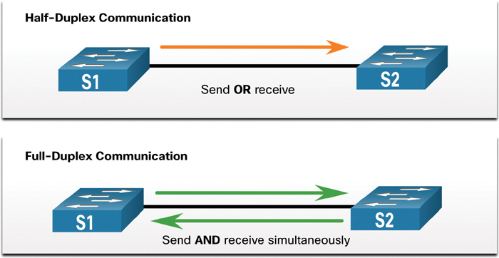
Figure 17-22 Duplex Operation
Interconnected Ethernet interfaces must operate in the same duplex mode for best communication performance and to avoid inefficiency and latency on the link.
The Ethernet autonegotiation feature facilitates configuration, minimizes problems, and maximizes link performance between two interconnecting Ethernet links. The connected devices first announce their supported capabilities and then choose the highest performance mode supported by both ends. For example, the switch and router in Figure 17-23 have successfully autonegotiated full-duplex mode.

Figure 17-23 Duplex Autonegotiation
If one of the two connected devices is operating in full-duplex and the other is operating in half-duplex, a duplex mismatch occurs. While data communication can occur through a link with a duplex mismatch, link performance is very poor.
Duplex mismatches are typically caused by misconfigured interfaces or, in rare instances, by failed autonegotiation. Duplex mismatches may be difficult to troubleshoot as the communication between devices still occurs.
IP Addressing Issues on IOS Devices (17.7.2)
IP address-related problems are likely to prevent remote network devices from communicating. Because IP addresses are hierarchical, any IP address assigned to a network device must conform to that range of addresses in that network. Wrongly assigned IP addresses create a variety of issues, including IP address conflicts and routing problems.
Two common causes of incorrect IPv4 assignment are manual assignment mistakes and DHCP-related issues.
Network administrators often have to manually assign IP addresses to devices such as servers and routers. If a mistake is made during the assignment, communications issues with the device are very likely to occur.
On an IOS device, use the show ip interface command or the show ip interface brief command to verify what IPv4 addresses are assigned to the network interfaces. For example, issuing the show ip interface brief command as shown in Example 17-32 would validate the interface status on R1.
Example 17-32 Using show ip interface brief to Verify IPv4 Addressing on a Cisco Device
R1# show ip interface brief
Interface               IP-Address       OK? Method  Status                Protocol
GigabitEthernet0/0/0    209.165.200.225  YES manual  up                    up
GigabitEthernet0/0/1    192.168.10.1     YES manual  up                    up
Serial0/1/0             unassigned       NO  unset   down                  down
Serial0/1/1             unassigned       NO  unset   down                  down
GigabitEthernet0        unassigned       YES unset   administratively down down
R1#
IP Addressing Issues on End Devices (17.7.3)
In Windows-based machines, when a device cannot contact a DHCP server, Windows automatically assigns an address belonging to the 169.254.0.0/16 range. This automatic addressing, called Automatic Private IP Addressing (APIPA), is designed to facilitate communication within the local network. Think of it as Windows saying, “I will use this address from the 169.254.0.0/16 range because I could not get any other address.”
Often, a computer with an APIPA address cannot communicate with other devices in the network because those devices most likely do not belong to the 169.254.0.0/16 network. Such a situation indicates an automatic IPv4 address assignment problem that should be fixed.
Note
Other operating systems, such Linux and macOS, do not assign an IPv4 address to the network interface if communication with a DHCP server fails.
Most end devices are configured to rely on a DHCP server for automatic IPv4 address assignment. If a device is unable to communicate with the DHCP server, the server cannot assign an IPv4 address for the specific network, and the device is unable to communicate.
To verify the IP addresses assigned to a Windows-based computer, use the ipconfig command, as shown in Example 17-33.
Example 17-33 Using ipconfig to Verify IPv4 Addressing on a Windows Host
C:UsersPC-A> ipconfig
Windows IP Configuration
(Output omitted)
Wireless LAN adapter Wi-Fi:
   Connection-specific DNS Suffix  . :
   Link-local IPv6 Address . . . . . : fe80::a4aa:2dd1:ae2d:a75e%16
   IPv4 Address. . . . . . . . . . . : 192.168.10.10
   Subnet Mask . . . . . . . . . . . : 255.255.255.0
   Default Gateway . . . . . . . . . : 192.168.10.1
(Output omitted)
Default Gateway Issues (17.7.4)
The default gateway for an end device is the closest networking device that can forward traffic to other networks. If a device has an incorrect or nonexistent default gateway address, it is unable to communicate with devices in remote networks. Because the default gateway is the path to remote networks, its address must belong to the same network as the end device.
The address of the default gateway can be manually set or obtained from a DHCP server. Much like IPv4 addressing issues, default gateway problems can be related to misconfiguration (in the case of manual assignment) or DHCP problems (if automatic assignment is in use).
To solve misconfigured default gateway issues, ensure that the device has the correct default gateway configured. If the default address was manually set but is incorrect, you can simply replace it with the proper address. If the default gateway address was automatically set, you need to ensure that the device can communicate with the DHCP server. It is also important to verify that the proper IPv4 address and subnet mask were configured on the interface of the router and that the interface is active.
To verify the default gateway on a Windows-based computer, use the ipconfig command, as shown in Example 17-34.
Example 17-34 Using ipconfig to Verify the Default Gateway on a Windows Host
C:UsersPC-A> ipconfig
Windows IP Configuration
(Output omitted)
Wireless LAN adapter Wi-Fi:
   Connection-specific DNS Suffix  . :
   Link-local IPv6 Address . . . . . : fe80::a4aa:2dd1:ae2d:a75e%16
   IPv4 Address. . . . . . . . . . . : 192.168.10.10
   Subnet Mask . . . . . . . . . . . : 255.255.255.0
   Default Gateway . . . . . . . . . : 192.168.10.1
(Output omitted)
On a router, use the show ip route command to list the routing table and verify that the default gateway, known as a default route, has been set. This route is used when the destination address of the packet does not match any other routes in its routing table.
The output in Example 17-35 verifies that R1 has a default gateway (that is, gateway of last resort) configured, and it is pointing to IP address 209.168.200.226.
In Example 17-35, the first highlighted line basically states that the gateway to any (that is, 0.0.0.0) should be sent to IP address 209.165.200.226. The second highlighted line shows how R1 learned about the default gateway. In this case, R1 received the information from another OSPF-enabled router.
Example 17-35 Using show ip route to Verify the Default Gateway on a Router
R1# show ip route | begin Gateway
Gateway of last resort is 209.165.200.226 to network 0.0.0.0
O*E2  0.0.0.0/0 [110/1] via 209.165.200.226, 02:19:50, GigabitEthernet0/0/0
      10.0.0.0/24 is subnetted, 1 subnets
O        10.1.1.0 [110/3] via 209.165.200.226, 02:05:42, GigabitEthernet0/0/0
      192.168.10.0/24 is variably subnetted, 2 subnets, 2 masks
C        192.168.10.0/24 is directly connected, GigabitEthernet0/0/1
L        192.168.10.1/32 is directly connected, GigabitEthernet0/0/1
      209.165.200.0/24 is variably subnetted, 3 subnets, 2 masks
C        209.165.200.224/30 is directly connected, GigabitEthernet0/0/0
L        209.165.200.225/32 is directly connected, GigabitEthernet0/0/0
O        209.165.200.228/30
           [110/2] via 209.165.200.226, 02:07:19, GigabitEthernet0/0/0
R1#
Troubleshooting DNS Issues (17.7.5)
Domain Name System (DNS) is an automated service that matches a website name, such as www.cisco.com, with an IP address. Although DNS resolution is not crucial to device communication, it is very important to the end user.
It is common for users to mistakenly relate the operation of an internet link to the availability of DNS. User complaints such as “the network is down” or “the internet is down” are often caused by unreachable DNS servers. While packet routing and all other network services are still operational, DNS failures often lead the user to the wrong conclusion. If a user types in a domain name such as www.cisco.com in a web browser and the DNS server is unreachable, the name will not be translated into an IP address, and the website will not display.
DNS server addresses can be manually or automatically assigned. Network administrators are often responsible for manually assigning DNS server addresses on servers and other devices, while DHCP is used to automatically assign DNS server addresses to clients.
Although it is common for companies and organizations to manage their own DNS servers, any reachable DNS server can be used to resolve names. Small office and home office (SOHO) users often rely on the DNS server maintained by their ISP for name resolution. ISP-maintained DNS servers are assigned to SOHO customers via DHCP. In addition, Google maintains a public DNS server that can be used by anyone; it is very useful for testing. The IPv4 address of Google’s public DNS server is 8.8.8.8, and 2001:4860:4860::8888 is its IPv6 DNS address.
Cisco offers OpenDNS, which provides secure DNS service by filtering phishing and some malware sites. You can change your DNS addresses to 208.67.222.222 and 208.67.220.220 in the Preferred DNS server and Alternate DNS server fields. Advanced features such as web content filtering and security are available to families and businesses.
Use the ipconfig /all command, as shown in Example 17-36, to verify which DNS server a Windows computer is using.
Example 17-36 Using ipconfig /all to Verify the DNS Server in Use on a Windows Host
C:UsersPC-A> ipconfig /all
(Output omitted)
Wireless LAN adapter Wi-Fi:
   Connection-specific DNS Suffix  .  :
   Description . . . . . . . . . . .  : Intel(R) Dual Band Wireless-AC 8265
   Physical Address. . . . . . . . .  : F8-94-C2-E4-C5-0A
   DHCP Enabled. . . . . . . . . . .  : Yes
   Autoconfiguration Enabled . . . .  : Yes
   Link-local IPv6 Address . . . . .  : fe80::a4aa:2dd1:ae2d:a75e%16(Preferred)
   IPv4 Address. . . . . . . . . . .  : 192.168.10.10(Preferred)
   Subnet Mask . . . . . . . . . . .  : 255.255.255.0
   Lease Obtained. . . . . . . . . .  : August 17, 2019 1:20:17 PM
   Lease Expires . . . . . . . . . .  : August 18, 2019 1:20:18 PM
   Default Gateway . . . . . . . . .  : 192.168.10.1
   DHCP Server . . . . . . . . . . .  : 192.168.10.1
   DHCPv6 IAID . . . . . . . . . . .  : 100177090
   DHCPv6 Client DUID. . . . . . . .  : 00-01-00-01-21-F3-76-75-54-E1-AD-DE-DA-9A
   DNS Servers . . . . . . . . . . .  : 208.67.222.222
   NetBIOS over Tcpip. . . . . . . .  : Enabled
(Output omitted)
The nslookup command is another useful DNS troubleshooting tool for PCs. With nslookup, a user can manually place DNS queries and analyze the DNS responses. The nslookup command in Example 17-37 shows the output for a query for www.cisco.com. Notice that you can also simply enter an IP address, and nslookup will resolve the name.
Note
For various reasons, it is not always possible to type an IP address in nslookup and receive the domain name. One of the most common reasons for this is that most websites run on servers that support multiple sites.
Example 17-37 Using nslookup on a Windows Host to Verify DNS Information
C:UsersPC-A> nslookup
Default Server:  Home-Net
Address:  192.168.1.1
> cisco.com
Server:  Home-Net
Address:  192.168.1.1
Non-authoritative answer:
Name:    cisco.com
Addresses:  2001:420:1101:1::185
          72.163.4.185
> 8.8.8.8
Server:  Home-Net
Address:  192.168.1.1
Name:    dns.google
Address:  8.8.8.8
>
> 208.67.222.222
Server:  Home-Net
Address:  192.168.1.1
Name:    resolver1.opendns.com
Address:  208.67.222.222
>
Lab—Troubleshoot Connectivity Issues (17.7.6)
In this lab, you will complete the following objectives:
Identify the Problem
Implement Network Changes
Verify Full Functionality
Document Findings and Configuration Changes
Packet Tracer—Troubleshoot Connectivity Issues (17.7.7)
The objective of this Packet Tracer activity is to troubleshoot and resolve connectivity issues, if possible. Otherwise, the issues should be clearly documented so they can be escalated.
Summary (17.8)
The following is a summary of the topics in the chapter and their corresponding online modules.
Devices in a Small Network
A small network typically has a single WAN connection provided by DSL, cable, or an Ethernet connection. A small network is managed by a local IT technician or by a contracted professional. Factors to consider when selecting network devices for a small network are cost, speed, types of ports/interfaces, expandability, and OS features and services. When implementing a network, create an IP addressing scheme and use it on end devices, servers and peripherals, and intermediary devices. Redundancy can be accomplished by installing duplicate equipment, but it can also be accomplished by supplying duplicate network links for critical areas. The routers and switches in a small network should be configured to support real-time traffic, such as voice and video, in an appropriate manner relative to other data traffic. In fact, a good network design implements quality of service (QoS) to classify traffic carefully according to priority.
Small Network Applications and Protocols
Two forms of software programs or processes provide access to a network: network applications and application layer services. Some end-user applications implement application layer protocols and are able to communicate directly with the lower layers of the protocol stack. Email clients and web browsers are examples of this type of application. Other programs may need the assistance of application layer services to use network resources such as file transfer or network print spooling. These are the programs that interface with the network and prepare the data for transfer. The two most common remote access solutions are Telnet and Secure Shell (SSH). SSH is a secure alternative to Telnet. Network administrators must also support common network servers and their required related network protocols, such as web servers, email servers, FTP servers, DHCP servers, and DNS servers. Businesses today are increasingly using IP telephony and streaming media to communicate with customers and business partners. These are real-time applications. The network infrastructure must therefore support VoIP, IP telephony, and other real-time applications.
Scale to Larger Networks
To scale a network, several elements are required: network documentation, device inventory, budget, and traffic analysis. It is important to know the type of traffic that is crossing the network as well as the current traffic flow. Capture traffic during peak utilization times to get a good representation of the different traffic types and perform the capture on different network segments and devices as some traffic will be local to a particular segment. Network administrators must know how network use is changing. Usage details of employee computers can be captured in a “snapshot” with tools such as the Windows Task Manager, Event Viewer, and Data Usage.
Verify Connectivity
Using the ping command is the most effective way to quickly test Layer 3 connectivity between a source IP address and a destination IP address. This command also displays various round-trip time statistics. Cisco IOS offers an “extended” mode of the ping command, which lets the user create special types of pings by adjusting parameters related to the command operation. Extended ping is entered in privileged EXEC mode by typing ping without a destination IP address. traceroute can help locate Layer 3 problem areas in a network. A trace returns a list of hops as a packet is routed through a network. It is used to identify the point along the path where a problem can be found. In Windows, the command is tracert, whereas in Cisco IOS the equivalent command is traceroute. There is also an extended traceroute command. It allows an administrator to adjust parameters related to the command operation. The output derived from network commands contributes data to the network baseline. One method for starting a baseline is to copy and paste the results from an executed ping, traceroute, or other relevant commands into a text file. Such text files can be timestamped with the date and saved into an archive for later retrieval and comparison.
Host and IOS Commands
Network administrators view IP addressing information (address, mask, router, and DNS) on a Windows host by issuing the ipconfig command. Other necessary commands are ipconfig /all, ipconfig /release and ipconfig /renew, and ipconfig /displaydns. Verifying IP settings by using the GUI on a Linux machine differs depending on the Linux distribution (distro) and desktop interface. Necessary commands are ifconfig and ip address. In the GUI of a Mac host, open Network Preferences > Advanced to get the IP addressing information. Other IP addressing commands for Mac are ifconfig, networksetup -listallnetworkservices, and networksetup -getinfo <network service>. The arp command, which is executed from the Windows, Linux, or Mac command prompt, lists all devices currently in the ARP cache of the host and includes the IPv4 address, physical address, and type of addressing (static/dynamic) for each device. The arp -a command displays the known IP address and MAC address binding. Common show commands are show running-config, show interfaces, show ip address, show arp, show ip route, show protocols, and show version. The show cdp neighbor command provides the following information about each CDP neighbor device: identifiers, address list, port identifier, capabilities list, and platform. The show cdp neighbors detail command helps determine if one of the CDP neighbors has an IP configuration error. The show ip interface brief command output displays all interfaces on the router, the IP address assigned to each interface, if any, and the operational status of the interface.
Troubleshooting Methodologies
Step 1. Identify the problem.
Step 2. Establish a theory of probable causes.
Step 3. Test the theory to determine the cause.
Step 4. Establish a plan of action and implement the solution.
Step 5. Verify the solution and implement preventive measures.
Step 6. Document findings, actions, and outcomes.
A problem should be escalated when it requires the decision of a manager, some specific expertise, or network access level unavailable to the troubleshooting technician. OS processes, protocols, mechanisms, and events generate messages to communicate their status. The IOS debug command allows an administrator to display these messages in real time for analysis. To display log messages on a terminal (virtual console), use the terminal monitor privileged EXEC command.
Troubleshooting Scenarios
There are two duplex communication modes: half-duplex and full-duplex. If one of two connected devices is operating in full-duplex and the other is operating in half-duplex, a duplex mismatch occurs. While data communication can occur through a link with a duplex mismatch, link performance is very poor.
Incorrectly assigned IP addresses create a variety of issues, including IP address conflicts and routing problems. Two common causes of incorrect IPv4 assignment are manual assignment mistakes and DHCP-related issues. Typically, an end device is configured to rely on a DHCP server for automatic IPv4 address assignment. If a device is unable to communicate with the DHCP server, then the server cannot assign an IPv4 address for the specific network, and the device is unable to communicate.
The default gateway for an end device is the closest networking device that can forward traffic to other networks. If a device has an incorrect or nonexistent default gateway address, it is unable to communicate with devices in remote networks. Because the default gateway is the path to remote networks, its address must belong to the same network as the end device.
DNS failures often lead users to conclude that the network is down. If a user types in a domain name such as www.cisco.com in a web browser, and the DNS server is unreachable, the name is not translated into an IP address, and the website does not appear.
Lab—Design and Build a Small Business Network (17.8.1)
In this lab, you will design and build a network.
Packet Tracer—Skills Integration Challenge (17.8.2)
In this Packet Tracer activity, you will use all the skills you have acquired throughout this book.
Packet Tracer—Troubleshooting Challenge (17.8.3)
In this Packet Tracer activity, you will troubleshoot and resolve a number of issues in an existing network.
Practice
The following activities provide practice with the topics introduced in this chapter. The lab is available in the companion Introduction to Networks Labs & Study Guide (CCNAv7) (ISBN 9780136634454). The Packet Tracer activity instructions are also provided in the Labs & Study Guide. The PKA files are available in the online course.
Labs
Lab 17.4.6: Test Network Latency with Ping and Traceroute
Lab 17.7.6: Troubleshoot Connectivity Issues
Lab 17.8.1: Design and Build a Small Network
Packet Tracer Activities
Packet Tracer 17.5.9: Interpret show Command Output
Packet Tracer 17.7.7: Troubleshoot Connectivity Issues
Packet Tracer 17.8.2: Skills Integration Challenge
Packet Tracer 17.8.3: Troubleshooting Challenge
Check Your Understanding Questions
Complete all the review questions listed here to test your understanding of the topics and concepts in this chapter. The appendix “Answers to ‘Check Your Understanding’ Questions” lists the answers.
1. Which network design consideration would be more important to a large corporation than to a small business?
Internet router
firewall
low port density switch
redundancy
2. A newly hired network technician is given the task of ordering new hardware for a small business with a large growth forecast. Which primary factor should the technician be concerned with when choosing the new devices?
devices with a fixed number and type of interfaces
devices that have support for network monitoring
redundant devices
devices with support for modularity
3. What type of traffic would most likely have the highest priority through a network?
FTP
instant messaging
voice
SNMP
4. A network technician is investigating network connectivity from a PC to a remote host with the address 10.1.1.5. Which command, when issued on a Windows PC, displays the path to the remote host?
trace 10.1.1.5
traceroute 10.1.1.5
tracert 10.1.1.5
ping 10.1.1.5
5. A user is unable to reach the website when typing http://www.cisco.com in a web browser. However, she can reach the same site by typing http://72.163.4.185. What is the issue?
default gateway
DHCP
DNS
TCP/IP protocol stack
6. Where are Cisco IOS debug output messages sent by default?
memory buffers
vty lines
syslog server
console line
7. Which element of scaling a network involves identifying the physical and logical topologies?
traffic analysis
network documentation
device inventory
cost analysis
8. What mechanism can be implemented in a small network to help minimize network latency for real-time streaming applications?
QoS
PoE
AAA
ICMP
9. Which process failed if a computer cannot access the internet and received the IPv4 address 169.254.142.5?
IP
DNS
DHCP
HTTP
10. A small company has only one router as the exit point to its ISP. Which solution could be adopted to maintain connectivity if the router itself, or its connection to the ISP, fails?
Activate another router interface that is connected to the ISP so the traffic can flow through it.
Have a second router that is connected to another ISP.
Purchase a second least-cost link from another ISP to connect to this router.
Add more interfaces to the router that is connected to the internal network.
11. When should an administrator establish a network baseline?
when the traffic is at peak in the network
when there is a sudden drop in traffic
at the lowest point of traffic in the network
at regular intervals over a period of time
12. Which two traffic types require delay-sensitive delivery? (Choose two.)
email
web
FTP
voice
video
13. A network technician suspects that a particular network connection between two Cisco switches is experiencing a duplex mismatch. Which command would the technician use to see the Layer 1 and Layer 2 details of a switch port?
show interfaces
show running-config
show ip interface brief
show mac address-table
14. Which statement is true about CDP on a Cisco device?
The show cdp neighbor detail command reveals the IP address of a neighbor only if there is Layer 3 connectivity.
To disable CDP globally, the no cdp enable command must be used in interface configuration mode.
CDP can be disabled globally or on a specific interface.
Because it runs at the data link layer, CDP can only be implemented in switches.
15. What factor should be considered in the design of a small network when devices are being chosen?
cost of devices
redundancy
traffic analysis
ISP