Chapter 10
Basic Router Configuration
Objectives
Upon completion of this chapter, you will be able to answer the following questions:
How do you configure initial settings on a Cisco IOS router?
How do you configure two active interfaces on a Cisco IOS router?
How do you configure devices to use the default gateway?
Introduction (10.0)
Have you ever run a relay race? The first person runs the first leg of the race and hands off the baton to the next runner, who continues forward in the second leg of the race and hands off the baton to the third runner, and so on. If the first runner does not know where to find the second runner, or if the first runner drops the baton before handing it off, then that relay team will most certainly lose the race.
Packet routing is similar to a relay. As you know, routing tables are created and used by routers to forward packets from their local networks on to other networks. But a router cannot create a routing table or forward any packets until it has been configured. If you plan to become a network administrator, you definitely must know how to do this. The good news? It is easy! This chapter includes Syntax Checker activities so that you can practice your configuration commands and see the output. There are also some Packet Tracer activities to get you started. Let’s go!
Configure Initial Router Settings (10.1)
This section presents the basic configuration needed for all IOS routers.
Basic Router Configuration Steps (10.1.1)
The following tasks should be completed to configure the initial settings on a router:

Step 1. Configure the device name:
Router(config)# hostname hostname
Step 2. Secure privileged EXEC mode:
Router(config)# enable secret password
Step 3. Secure user EXEC mode:
Router(config)# line console 0
Router(config-line)# password password
Router(config-line)# login
Step 4. Secure remote Telnet/SSH access:
Router(config-line)# line vty 0 4
Router(config-line)# password password
Router(config-line)# login
Router(config-line)# transport input {ssh | telnet}
Step 5. Secure all passwords in the config file:
Router(config-line)# exit
Router(config)# service password-encryption
Step 6. Provide a legal notification banner:
Router(config)# banner motd delimiter message delimiter
Step 7. Save the configuration:
Router(config)# end
Router# copy running-config startup-config
Basic Router Configuration Example (10.1.2)
This section provides an example, using the topology in Figure 10-1. In this example, you will see how to configure router R1 with initial settings.

Figure 10-1 Basic Router Configuration Reference Topology
To configure the device name for R1, use the commands in Example 10-1.
Example 10-1 Configuring a Device Name
Router> enable
Router# configure terminal
Enter configuration commands, one per line.
End with CNTL/Z.
Router(config)# hostname R1
R1(config)#
Note
Notice in Example 10-1 that the router prompt now displays hostname.
All router access should be secured. Privileged EXEC mode provides a user with complete access to a device and its configuration. Therefore, it is the most important mode to secure.
The commands in Example 10-2 secure privileged EXEC mode and user EXEC mode, enable Telnet and SSH remote access, and encrypt all plaintext (that is, user EXEC and vty line) passwords.
Example 10-2 Securing Access to a Router
R1(config)# enable secret class
R1(config)#
R1(config)# line console 0
R1(config-line)# password cisco
R1(config-line)# login
R1(config-line)# exit
R1(config)#
R1(config)# line vty 0 4
R1(config-line)# password cisco
R1(config-line)# login
R1(config-line)# transport input ssh telnet
R1(config-line)# exit
R1(config)#
R1(config)# service password-encryption
R1(config)#
It is a good idea to provide a legal notification that warns users that the device should be accessed only by permitted users. Legal notification is configured as shown in Example 10-3.
Example 10-3 Configuring a Banner Warning
R1(config)# banner motd #
Enter TEXT message. End with a new line and the #
***********************************************
WARNING: Unauthorized access is prohibited!
***********************************************
#
R1(config)#
If the commands shown so far are all entered on a router that accidentally loses power, all this configuration is lost. For this reason, it is important to save the configuration when changes are implemented. The command shown in Example 10-4 saves the configuration to NVRAM.
Example 10-4 Saving the Running Configuration
R1# copy running-config startup-config
Destination filename [startup-config]?
Building configuration...
[OK]
R1#
Syntax Checker—Configure Initial Router Settings (10.1.3)

Use this Syntax Checker activity to practice configuring the initial settings on a router:
Configure the device name.
Secure the privileged EXEC mode.
Secure and enable remote SSH and Telnet access.
Secure all plaintext passwords.
Provide legal notification.
Refer to the online course to complete this activity.
Packet Tracer—Configure Initial Router Settings (10.1.4)

In this activity, you will perform basic router configurations. You will secure access to the CLI and console port using encrypted and plaintext passwords. You will also configure messages for users logging in to the router. These banners also warn unauthorized users that access is prohibited. Finally, you will verify and save your running configuration.
Configure Interfaces (10.2)
This section introduces the basic router interface configuration.
Configure Router Interfaces (10.2.1)
When your routers have basic configurations, the next step is to configure their interfaces. This is necessary because routers are not reachable by end devices until the interfaces are configured. There are many different types of interfaces available on Cisco routers. For example, the Cisco ISR 4321 router is equipped with two Gigabit Ethernet interfaces:
GigabitEthernet 0/0/0 (G0/0/0)
GigabitEthernet 0/0/1 (G0/0/1)
Configuring a router interface is similar to configuring a management SVI on a switch. Specifically, it involves issuing the following commands:
Router(config)# interface type-and-number
Router(config-if)# description description-text
Router(config-if)# ip address ipv4-address subnet-mask
Router(config-if)# ipv6 address ipv6-address/prefix-length
Router(config-if)# no shutdown
Note
When a router interface is enabled, information messages should be displayed to confirm the enabled link.
Although the description command is not required to enable an interface, using it is a good practice. This command can be helpful in troubleshooting on production networks because it enables you to provide information about the type of network connected. For example, for an interface that connects to an ISP or a service carrier, you can use the description command to enter the third-party connection and contact information.
Note
description-text is limited to 240 characters.
Using the no shutdown command activates the interface and is similar to powering on the interface. The interface must also be connected to another device, such as a switch or a router, for the physical layer to be active.
Note
On inter-router connections where there is no Ethernet switch, both interconnecting interfaces must be configured and enabled.
Configure Router Interfaces Example (10.2.2)
Example 10-5 shows how to enable the directly connected interfaces of R1 in Figure 10-1.
Example 10-5 Configuring the Router Interfaces with Dual Stack Addressing
R1> enable
R1# configure terminal
Enter configuration commands, one per line.
End with CNTL/Z.
R1(config)# interface gigabitEthernet 0/0/0
R1(config-if)# description Link to LAN
R1(config-if)# ip address 192.168.10.1 255.255.255.0
R1(config-if)# ipv6 address 2001:db8:acad:10::1/64
R1(config-if)# no shutdown
R1(config-if)# exit
R1(config)#
*Aug  1 01:43:53.435: %LINK-3-UPDOWN: Interface GigabitEthernet0/0/0, changed state
  to down
*Aug  1 01:43:56.447: %LINK-3-UPDOWN: Interface GigabitEthernet0/0/0, changed state
  to up
*Aug  1 01:43:57.447: %LINEPROTO-5-UPDOWN: Line protocol on Interface
  GigabitEthernet0/0/0, changed state to up
R1(config)#
R1(config)#
R1(config)# interface gigabitEthernet 0/0/1
R1(config-if)# description Link to R2
R1(config-if)# ip address 209.165.200.225 255.255.255.252
R1(config-if)# ipv6 address 2001:db8:feed:224::1/64
R1(config-if)# no shutdown
R1(config-if)# exit
R1(config)#
*Aug  1 01:46:29.170: %LINK-3-UPDOWN: Interface GigabitEthernet0/0/1, changed state
  to down
*Aug  1 01:46:32.171: %LINK-3-UPDOWN: Interface GigabitEthernet0/0/1, changed state
  to up
*Aug  1 01:46:33.171: %LINEPROTO-5-UPDOWN: Line protocol on Interface
  GigabitEthernet0/0/1, changed state to up
R1(config)#
Note
Notice the informational messages that says G0/0/0 and G0/0/1 are enabled.
Verify Interface Configuration (10.2.3)
Several commands can be used to verify interface configuration. The most useful of them are the show ip interface brief and show ipv6 interface brief commands, as shown in Example 10-6.
Example 10-6 Verifying the Interface Configuration
R1# show ip interface brief
Interface             IP-Address      OK? Method Status                Protocol
GigabitEthernet0/0/0  192.168.10.1    YES manual up                    up
GigabitEthernet0/0/1  209.165.200.225 YES manual up                    up
Vlan1                 unassigned      YES unset  administratively down down
R1# show ipv6 interface brief
GigabitEthernet0/0/0       [up/up]
    FE80::201:C9FF:FE89:4501
    2001:DB8:ACAD:10::1
GigabitEthernet0/0/1       [up/up]
    FE80::201:C9FF:FE89:4502
    2001:DB8:FEED:224::1
Vlan1                      [administratively down/down]
    unassigned
R1#
Configuration Verification Commands (10.2.4)
Table 10-1 describes the show commands that are most commonly used to verify interface configuration.
Table 10-1 Verification Commands
Commands |
Output Description |
show ip interface brief show ipv6 interface brief |
Displays all interfaces, their IP addresses, and their current status. The configured and connected interfaces should indicate up under Status and up under Protocol. Anything else indicates a problem with either the configuration or the cabling. |
show ip route show ipv6 route |
Displays the contents of the IP routing tables stored in RAM. |
show interfaces |
Displays statistics for all interfaces on the device. However, this command displays only the IPv4 addressing information. |
show ip interfaces |
Displays the IPv4 statistics for all interfaces on a router. |
show ipv6 interface |
Displays the IPv6 statistics for all interfaces on a router. |
Examples 10-7 through 10-13 show the command output for these configuration verification commands.
Example 10-7 The show ip interface brief Command
R1# show ip interface brief
Interface             IP-Address      OK? Method Status                Protocol
GigabitEthernet0/0/0  192.168.10.1    YES manual up                    up
GigabitEthernet0/0/1  209.165.200.225 YES manual up                    up
Vlan1                 unassigned      YES unset  administratively down down
R1#
Example 10-8 The show ipv6 interface brief Command
R1# show ipv6 interface brief
GigabitEthernet0/0/0       [up/up]
    FE80::201:C9FF:FE89:4501
    2001:DB8:ACAD:10::1
GigabitEthernet0/0/1       [up/up]
    FE80::201:C9FF:FE89:4502
    2001:DB8:FEED:224::1
Vlan1                      [administratively down/down]
    unassigned
R1#
Example 10-9 The show ip route Command
R1# show ip route
Codes:  L - local, C - connected, S - static, R - RIP, M - mobile, B - BGP
       D - EIGRP, EX - EIGRP external, O - OSPF, IA - OSPF inter area
       N1 - OSPF NSSA external type 1, N2 - OSPF NSSA external type 2
       E1 - OSPF external type 1, E2 - OSPF external type 2
       i - IS-IS, su - IS-IS summary, L1 - IS-IS level-1, L2 - IS-IS level-2
       ia - IS-IS inter area, * - candidate default, U - per-user static route
       o - ODR, P - periodic downloaded static route, H - NHRP, l - LISP
       a - application route
       + - replicated route, % - next hop override, p - overrides from PfR
Gateway of last resort is not set
      192.168.10.0/24 is variably subnetted, 2 subnets, 2 masks
C        192.168.10.0/24 is directly connected, GigabitEthernet0/0/0
L        192.168.10.1/32 is directly connected, GigabitEthernet0/0/0
      209.165.200.0/24 is variably subnetted, 2 subnets, 2 masks
C        209.165.200.224/30 is directly connected, GigabitEthernet0/0/1
L        209.165.200.225/32 is directly connected, GigabitEthernet0/0/1
R1#
Example 10-10 The show ipv6 route Command
R1# show ipv6 route
IPv6 Routing Table - default - 5 entries
Codes:  C - Connected, L - Local, S - Static, U - Per-user Static route
        B - BGP, R - RIP, H - NHRP, I1 - ISIS L1
        I2 - ISIS L2, IA - ISIS interarea, IS - ISIS summary, D - EIGRP
        EX - EIGRP external, ND - ND Default, NDp - ND Prefix, DCE - Destination
        NDr - Redirect, RL - RPL, O - OSPF Intra, OI - OSPF Inter
        OE1 - OSPF ext 1, OE2 - OSPF ext 2, ON1 - OSPF NSSA ext 1
        ON2 - OSPF NSSA ext 2, a - Application
C   2001:DB8:ACAD:10::/64 [0/0]
     via GigabitEthernet0/0/0, directly connected
L   2001:DB8:ACAD:10::1/128 [0/0]
     via GigabitEthernet0/0/0, receive
C   2001:DB8:FEED:224::/64 [0/0]
     via GigabitEthernet0/0/1, directly connected
L   2001:DB8:FEED:224::1/128 [0/0]
     via GigabitEthernet0/0/1, receive
L   FF00::/8 [0/0]
     via Null0, receive
R1#
Example 10-11 The show interfaces Command
R1# show interfaces gig0/0/0
GigabitEthernet0/0/0 is up, line protocol is up
  Hardware is ISR4321-2x1GE, address is a0e0.af0d.e140 (bia a0e0.af0d.e140)
  Description: Link to LAN
  Internet address is 192.168.10.1/24
  MTU 1500 bytes, BW 100000 Kbit/sec, DLY 100 usec,
     reliability 255/255, txload 1/255, rxload 1/255
  Encapsulation ARPA, loopback not set
  Keepalive not supported
  Full Duplex, 100Mbps, link type is auto, media type is RJ45
  output flow-control is off, input flow-control is off
  ARP type: ARPA, ARP Timeout 04:00:00
  Last input 00:00:01, output 00:00:35, output hang never
  Last clearing of "show interface" counters never
  Input queue: 0/375/0/0 (size/max/drops/flushes); Total output drops: 0
  Queueing strategy: fifo
  Output queue: 0/40 (size/max)
  5 minute input rate 0 bits/sec, 0 packets/sec
  5 minute output rate 0 bits/sec, 0 packets/sec
     1180 packets input, 109486 bytes, 0 no buffer
     Received 84 broadcasts (0 IP multicasts)
     0 runts, 0 giants, 0 throttles
     0 input errors, 0 CRC, 0 frame, 0 overrun, 0 ignored
     0 watchdog, 1096 multicast, 0 pause input
     65 packets output, 22292 bytes, 0 underruns
     0 output errors, 0 collisions, 2 interface resets
     11 unknown protocol drops
     0 babbles, 0 late collision, 0 deferred
     1 lost carrier, 0 no carrier, 0 pause output
     0 output buffer failures, 0 output buffers swapped out
R1#
Example 10-12 The show ip interface Command
R1# show ip interface g0/0/0
GigabitEthernet0/0/0 is up, line protocol is up
  Internet address is 192.168.10.1/24
  Broadcast address is 255.255.255.255
  Address determined by setup command
  MTU is 1500 bytes
  Helper address is not set
  Directed broadcast forwarding is disabled
  Outgoing Common access list is not set
  Outgoing access list is not set
  Inbound Common access list is not set
  Inbound  access list is not set
  Proxy ARP is enabled
  Local Proxy ARP is disabled
  Security level is default
  Split horizon is enabled
  ICMP redirects are always sent
  ICMP unreachables are always sent
  ICMP mask replies are never sent
  IP fast switching is enabled
  IP Flow switching is disabled
  IP CEF switching is enabled
  IP CEF switching turbo vector
  IP Null turbo vector
  Associated unicast routing topologies:
        Topology "base", operation state is UP
  IP multicast fast switching is enabled
  IP multicast distributed fast switching is disabled
  IP route-cache flags are Fast, CEF
  Router Discovery is disabled
  IP output packet accounting is disabled
  IP access violation accounting is disabled
  TCP/IP header compression is disabled
  RTP/IP header compression is disabled
  Probe proxy name replies are disabled
  Policy routing is disabled
  Network address translation is disabled
  BGP Policy Mapping is disabled
  Input features: MCI Check
  IPv4 WCCP Redirect outbound is disabled
  IPv4 WCCP Redirect inbound is disabled
  IPv4 WCCP Redirect exclude is disabled
R1#
Example 10-13 The show ipv6 interface Command
R1# show ipv6 interface g0/0/0
GigabitEthernet0/0/0 is up, line protocol is up
  IPv6 is enabled, link-local address is FE80::868A:8DFF:FE44:49B0
  No Virtual link-local address(es):
  Description: Link to LAN
  Global unicast address(es):
    2001:DB8:ACAD:10::1, subnet is 2001:DB8:ACAD:10::/64
  Joined group address(es):
    FF02::1
    FF02::1:FF00:1
    FF02::1:FF44:49B0
  MTU is 1500 bytes
  ICMP error messages limited to one every 100 milliseconds
  ICMP redirects are enabled
  ICMP unreachables are sent
  ND DAD is enabled, number of DAD attempts: 1
  ND reachable time is 30000 milliseconds (using 30000)
  ND NS retransmit interval is 1000 milliseconds
R1#
Syntax Checker—Configure Interfaces (10.2.5)
Use this Syntax Checker activity to practice configuring the GigabitEthernet 0/0 interface on a router:
Describe the link as Link to LAN.
Configure the IPv4 address as 192.168.10.1 with the subnet mask 255.255.255.0.
Configure the IPv6 address as 2001:db8:acad:10::1 with the /64 prefix length.
Activate the interface.
Refer to the online course to complete this activity.
Configure the Default Gateway (10.3)
To send a packet outside the local network, a device needs to know where to forward the packet. For an end device, this is generally called the default gateway. This section introduces the concept and use of the default gateway.
Default Gateway on a Host (10.3.1)
If a local network has only one router, that router is the gateway router, and all hosts and switches on the network must be configured with this information. If a local network has multiple routers, one of them must be designated as the default gateway router. This section explains how to configure the default gateway on hosts and switches.
For an end device to communicate over a network, it must be configured with the correct IP address information, including the default gateway address. The default gateway is used only when the host wants to send a packet to a device on another network. The default gateway address is generally the router interface address attached to the local network of the host. The IP address of the host device and the router interface address must be in the same network.
For example, say that an IPv4 network topology consists of a router interconnecting two separate LANs. G0/0/0 is connected to network 192.168.10.0, while G0/0/1 is connected to network 192.168.11.0. Each host device is configured with the appropriate default gateway address.
In Figure 10-2, if PC1 sends a packet to PC2, the default gateway is not used. Instead, PC1 addresses the packet with the IPv4 address of PC2 and forwards the packet directly to PC2 through the switch.

Figure 10-2 No Default Gateway Needed
What if PC1 sent a packet to PC3? PC1 would address the packet with the IPv4 address of PC3 but would forward the packet to its default gateway, which is the G0/0/0 interface of R1. The router accepts the packet and accesses its routing table to determine that G0/0/1 is the appropriate exit interface based on the destination address. R1 then forwards the packet out the appropriate interface to reach PC3, as shown in Figure 10-3.

Figure 10-3 Default Gateway Is Required
The same process would occur on an IPv6 network, although this is not shown in Figures 10-2 and 10-3. Devices would use the IPv6 address of the local router as their default gateway.
Default Gateway on a Switch (10.3.2)
A switch that interconnects client computers is typically a Layer 2 device. A Layer 2 switch does not require an IP address to function properly. However, IP settings can be configured on a switch to give an administrator remote access to the switch.
To connect to and manage a switch over a local IP network, that switch must have a switch virtual interface (SVI) configured. The SVI is configured with an IPv4 address and subnet mask on the local LAN. The switch must also have a default gateway address configured to remotely manage the switch from another network.
The default gateway address is typically configured on all devices that will communicate beyond their local network.
To configure an IPv4 default gateway on a switch, use the ip default-gateway ip-address global configuration command, where ip-address is the IPv4 address of the local router interface connected to the switch.
Figure 10-4 shows an administrator establishing a remote connection to switch S1 on another network and executing the show running-config command.
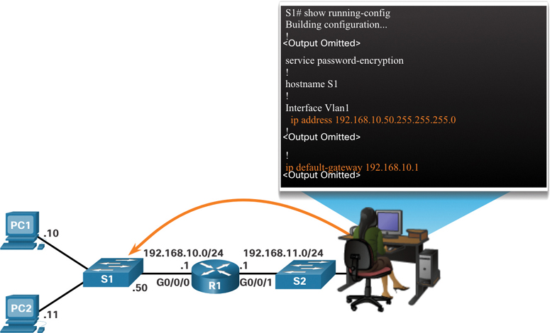
Figure 10-4 Remotely Accessing a Switch
In Figure 10-4, the administrator host would use its default gateway to send the packet to the G0/0/1 interface of R1. R1 would forward the packet to S1 out its G0/0/0 interface. Because the packet source IPv4 address is from another network, S1 would require a default gateway to forward the packet to the G0/0/0 interface of R1. Therefore, S1 must be configured with a default gateway to be able to reply and establish an SSH connection with the administrative host.
Note
Packets originating from host computers connected to the switch must already have the default gateway address configured on their host computer operating systems.
A workgroup switch can also be configured with an IPv6 address on an SVI. However, the switch does not require the IPv6 address of the default gateway to be configured manually. The switch automatically receives its default gateway from the ICMPv6 Router Advertisement message from the router.
Syntax Checker—Configure the Default Gateway (10.3.3)
Use this Syntax Checker activity to practice configuring the default gateway of a Layer 2 switch.
Refer to the online course to complete this activity.
Packet Tracer—Connect a Router to a LAN (10.3.4)
In this activity, you will use various show commands to display the current state of a router. You will then use the addressing table to configure router Ethernet interfaces. Finally, you will use commands to verify and test your configurations.
Packet Tracer—Troubleshoot Default Gateway Issues (10.3.5)
For a device to communicate across multiple networks, it must be configured with an IP address, a subnet mask, and a default gateway. The default gateway is used when the host wants to send a packet to a device on another network. The default gateway address is generally the router interface address attached to the local network to which the host is connected. In this activity, you will finish documenting the network. You will then verify the network documentation by testing end-to-end connectivity and troubleshooting issues. The troubleshooting method you will use consists of the following steps:
Step 1. Verify the network documentation and use tests to isolate problems.
Step 2. Determine an appropriate solution for a given problem.
Step 3. Implement the solution.
Step 4. Test to verify that the problem is resolved.
Step 5. Document the solution.
Summary (10.4)
The following is a summary of the topics in the chapter and their corresponding online modules.
Configure Initial Router Settings
The following tasks should be completed to configure the initial settings on a router:
Step 1. Configure the device name.
Step 2. Secure privileged EXEC mode.
Step 3. Secure user EXEC mode.
Step 4. Secure remote Telnet/SSH access.
Step 5. Secure all passwords in the config file.
Step 6. Provide a legal notification banner.
Step 7. Save the configuration.
Configure Interfaces
For routers to be reachable, the router interfaces must be configured. The Cisco ISR 4321 router is equipped with two Gigabit Ethernet interfaces: GigabitEthernet 0/0/0 (G0/0/0) and GigabitEthernet 0/0/1 (G0/0/1). Configuring a router interface is very similar to configuring a management SVI on a switch. Using the no shutdown command activates the interface. The interface must also be connected to another device, such as a switch or a router, for the physical layer to be active. Several commands can be used to verify interface configuration, including show ip interface brief, show ipv6 interface brief, show ip route, show ipv6 route, show interfaces, show ip interface, and show ipv6 interface.
Configure the Default Gateway
For an end device to communicate over the network, it must be configured with the correct IP address information, including the default gateway address. The default gateway address is generally the router interface address for the router that is attached to the local network of the host. The IP address of the host device and the router interface address must be in the same network. To connect to and manage a switch over a local IP network, it must have a switch virtual interface (SVI) configured. The SVI is configured with an IPv4 address and subnet mask on the local LAN. The switch must also have a default gateway address configured to remotely manage the switch from another network. To configure an IPv4 default gateway on a switch, use the ip default-gateway ip-address global configuration command. Use the IPv4 address of the local router interface that is connected to the switch.
Video—Network Device Differences: Part 1 (10.4.1)

Video—Network Device Differences: Part 2 (10.4.2)
Packet Tracer—Basic Device Configuration (10.4.3)
Your network manager is impressed with your performance in your job as a LAN technician. She would like you to now demonstrate your ability to configure a router connecting two LANs. Your tasks include configuring basic settings on a router and a switch using Cisco IOS. You will then verify your configurations as well as the configurations on existing devices by testing end-to-end connectivity.
Lab—Build a Switch and Router Network (10.4.4)
In this lab, you will complete the following objectives:
Part 1: Set Up the Topology and Initialize Devices
Part 2: Configure Devices and Verify Connectivity
Part 3: Display Device Information
Practice
The following activities provide practice with the topics introduced in this chapter. The lab is available in the companion Introduction to Networks Labs & Study Guide (CCNAv7) (ISBN 9780136634454). The Packet Tracer activity instructions are also provided in the Labs & Study Guide. The PKA files are available in the online course.
Lab
Lab 10.4.4: Build a Switch and Router Network
Packet Tracer Activities
Packet Tracer 10.1.4: Configure Initial Router Settings
Packet Tracer 10.3.4: Connect a Router to a LAN
Packet Tracer 10.3.5: Troubleshoot Default Gateway Issues
Packet Tracer 10.4.3: Basic Device Configuration
Check Your Understanding Questions
Complete all the review questions listed here to test your understanding of the topics and concepts in this chapter. The appendix “Answers to ‘Check Your Understanding’ Questions” lists the answers.
1. A router boots without any preconfigured commands. What is the reason for this?
The IOS image is corrupt.
Cisco IOS is missing from flash memory.
The configuration file is missing from NVRAM.
The POST process has detected hardware failure.
2. Which command is used to encrypt all passwords in a router configuration file?
Router_A(config)# enable secret <password>
Router_A(config)# service password-encryption
Router_A(config)# enable password <password>
Router_A(config)# encrypt password
3. Company policy requires you to use the most secure method to safeguard access to the privileged EXEC and configuration mode on the routers. The privileged EXEC password is trustknow1. Which of the following router commands achieves the goal of providing the highest level of security?
secret password trustknow1
enable password trustknow1
service password-encryption
enable secret trustknow1
4. What will be the command prompt from the router after the command router(config)# hostname portsmouth is entered?
portsmouth#
portsmouth(config)#
invalid input detected
hostname portsmouth#
? command not recognized
Router(config)#
5. An administrator is configuring a new router to permit out-of-band management access. Which set of commands will allow the required login using the password cisco?
Router(config)# line vty 0 4
Router(config-line) password manage
Router(config-line) exit
Router(config)# enable password cisco
Router(config)# line vty 0 4
Router(config-line) password cisco
Router(config-line) login
Router(config)# line console 0
Router(config-line) password cisco
Router(config-line) login
Router(config)# line console 0
Router(config-line) password cisco
Router(config-line) exit
Router(config)# service password-encryption
6. Which command can be used on a Cisco router to display all interfaces, the IPv4 address assigned, and the current status?
show ip interface brief
ping
show ip route
show interface fa0/1
7. Which CLI mode allows users to access all device commands, such as those used for configuration, management, and troubleshooting?
user EXEC mode
privileged EXEC mode
global configuration mode
interface configuration mode
8. What is the purpose of the startup configuration file on a Cisco router?
It facilitates the basic operation of the hardware components of a device.
It contains the commands that are used to initially configure a router on startup.
It contains the configuration commands that the router IOS is currently using.
It provides a limited backup version of IOS, in case the router cannot load the full-featured IOS.
9. Which characteristic describes the default gateway of a host computer?
the logical address of the router interface on the same network as the host computer
the physical address of the switch interface connected to the host computer
the physical address of the router interface on the same network as the host computer
the logical address assigned to the switch interface connected to the router
10. What is the purpose of the banner motd command?
It configures a message that identifies printed documents to LAN users.
Routers use it to communicate the status of their links with one another.
It provides an easy way of communicating with any user attached to a router’s LAN.
It provides a way to make announcements to those who log in to a router.
11. A technician is configuring a router to allow for all forms of management access. As part of each different type of access, the technician is trying to type the command login. Which configuration mode should be used to do this task?
user executive mode
global configuration mode
console line and vty line configuration modes
privileged EXEC mode
12. What is stored in the NVRAM of a Cisco router?
Cisco IOS
the running configuration
the bootup instructions
the startup configuration
13. Which statement regarding the service password-encryption command is true?
It is configured in privileged EXEC mode.
It encrypts only line mode passwords.
When the service password-encryption command is entered, all plaintext passwords are encrypted.
To see the passwords encrypted by the service password-encryption command in plaintext, issue the no service password-encryption command.