Chapter 15. Public Safety
The primary objectives of public safety organizations are to keep citizens, communities, and public spaces safe with faster response, improved operational efficiency, and reduced costs. Public safety and emergency response challenges are growing in complexity, and expectations are rising, with increasing demands for critical communications across a growing spectrum of voice, data, and video. In a crisis situation, every second counts. Potentially life-threatening situations change in a heartbeat, and decisions must be made in seconds.
Even though the Internet of Things is a fairly recent concept, it is already having a profound impact on public safety, where the demand for real-time information and situational awareness is ever present. IoT is a network of physical objects that can sense and communicate data. The technology enables users to take action based on intelligent data. In the case of public safety, there are, of course, smart objects, and this chapter provides some examples. However, the main concern of public safety is to be able to make fast use of data. IoT helps improve communications between people. IoT also helps public safety agents by preprocessing collected data, making emergency responders’ actions more effective.
Public safety is a broad area that includes fire and emergency responders, law enforcement and security forces (in public places and also specific locations, such as schools), coast guard and defense, custom and border protection, and many other fields involving the general public and the need to ensure safety or protection. Covering all aspects of public safety could fill an entire book. However, most public safety organizations have similar needs and benefit from improved operations through the adoption of IoT-driven technologies in the same way. This chapter focuses on IoT’s impact on typical cases of public safety needs: law enforcement, firefighting, emergency medical services (EMS), and school buses. In particular, this chapter includes the following sections:
![]() Overview of Public Safety: This section examines the different use cases for connected public safety, including the different objects, vehicles, and services that interact to allow for an efficient emergency response.
Overview of Public Safety: This section examines the different use cases for connected public safety, including the different objects, vehicles, and services that interact to allow for an efficient emergency response.
![]() An IoT Blueprint for Public Safety: This section explains the concept of mission continuum and lists the various elements needed to ensure the public safety mission.
An IoT Blueprint for Public Safety: This section explains the concept of mission continuum and lists the various elements needed to ensure the public safety mission.
![]() Emergency Response IoT Architecture: This section details the IoT and communication architectures needed for various emergency response vehicles, including the command center and mobile field vehicles.
Emergency Response IoT Architecture: This section details the IoT and communication architectures needed for various emergency response vehicles, including the command center and mobile field vehicles.
![]() IoT Public Safety Information Processing: This section provides an overview of how big data and information processing improve emergency response efficiency.
IoT Public Safety Information Processing: This section provides an overview of how big data and information processing improve emergency response efficiency.
![]() School Bus Safety: This section expands public safety applications to school buses to show how connected public vehicles can improve public services and safety.
School Bus Safety: This section expands public safety applications to school buses to show how connected public vehicles can improve public services and safety.
The information in this chapter can be extended to other IoT public safety use cases.
Overview of Public Safety
A common theme across public safety is the need to collect, analyze, and distribute information to enable individuals, workgroups, supervisors, and executives to carry out the missions of their respective agencies. These organizations depend on cross-agency collaboration among various groups of people, commonly referred to as the chain of command, to support public needs. This is true for both routine and emergency response events. Regardless of the event type, the safety of the public and the agency personnel themselves depend on the reliability, confidentiality, and integrity of their communications.
IoT is opening new possibilities for connecting agencies and enhancing situational awareness and response capabilities across the mission environment, helping provide the following:
![]() Real-time situational awareness
Real-time situational awareness
![]() Intra-agency communication and collaboration (for example, voice, data, video)
Intra-agency communication and collaboration (for example, voice, data, video)
![]() Data analytics and information sharing
Data analytics and information sharing
![]() Increased community engagement and stakeholder outreach
Increased community engagement and stakeholder outreach
Public Safety Objects and Exchanges
Public safety in the twenty-first century requires real-time interactions between citizens, field personnel, law enforcement, intelligent sensors, and intelligent analytics systems. As a result, a variety of IoT solutions are applicable to public safety cases. Intelligent sensors and alarms allow agencies to capture data and create a backhaul link between sensors and data collection points. Analytics tools process data and events at the tactical edge or in the cloud and provide a visual presentation of data and events for in-depth analysis and decision making. New applications for smart objects in relation to public safety appear every day, to the point that some authors create new categories of IoT, such as the Internet of First Responder Things (IoFST), or the Internet of Live-Saving Things (IoLST). The authors of this book believe that it is prudent to simply use the term IoT and examine the applications of IoT for public safety with the awareness that these applications broadly include three types of smart objects:
![]() Objects carried by first responders: These objects can be specialized sensors such as first responder vital sign recorders and transmitters and environmental sensors that collect information about temperature, presence of chemicals, and any other parameter likely to help the first responder assess hazards for immediate action or post-event analysis. They can also be general objects such as body cameras (recording locally or providing live feed to a central coordination and command station), or even smart phones. Data collected from these objects may also be processed locally or in the cloud (for example, gunshot-triggered alarm, image processing and analysis).
Objects carried by first responders: These objects can be specialized sensors such as first responder vital sign recorders and transmitters and environmental sensors that collect information about temperature, presence of chemicals, and any other parameter likely to help the first responder assess hazards for immediate action or post-event analysis. They can also be general objects such as body cameras (recording locally or providing live feed to a central coordination and command station), or even smart phones. Data collected from these objects may also be processed locally or in the cloud (for example, gunshot-triggered alarm, image processing and analysis).
![]() Objects that help the emergency services callers or victims: This general category includes a large variety of health devices, from basic panic buttons (connected to emergency responder call-in systems) to advanced health sensors (for example, health monitors that can trigger alarms and automated calls to emergency responders through a cell phone with detailed information about the detected issue).
Objects that help the emergency services callers or victims: This general category includes a large variety of health devices, from basic panic buttons (connected to emergency responder call-in systems) to advanced health sensors (for example, health monitors that can trigger alarms and automated calls to emergency responders through a cell phone with detailed information about the detected issue).
![]() Objects present in the environment: These are the smart objects described in the other chapters of this book that are likely to be present in public environments. (Refer to Chapter 12, “Smart and Connected Cities,” for detailed examples.) These sensors improve public safety by monitoring the environment (for example, street cameras, street light controls, environmental and smoke sensors, traffic location and density). Their data can be accessed by individual emergency responders, or it can be used to feed an emergency response agency to improve situational awareness or response efficiency.
Objects present in the environment: These are the smart objects described in the other chapters of this book that are likely to be present in public environments. (Refer to Chapter 12, “Smart and Connected Cities,” for detailed examples.) These sensors improve public safety by monitoring the environment (for example, street cameras, street light controls, environmental and smoke sensors, traffic location and density). Their data can be accessed by individual emergency responders, or it can be used to feed an emergency response agency to improve situational awareness or response efficiency.
Beyond smart objects, real-time voice and video helps responders exchange information faster and more reliably within a given agency. Human to human communication does not seem to be an IoT application. However, another impact of IoT on public safety is the increasing requirement to collect, store, and process rich voice, video, and data information in real time or for post-event analysis. IoT solutions are needed to collect and process data at the edge (fog computing), while only forwarding to the cloud in real time a subset of the collected and processed data, especially in locations and situations where the amount of data exceeds the uplink capabilities. A larger or complete data set can be forwarded to a centralized storage and processing facility when emergency responders access a fast connection. Here again, merely uploading everything is not sufficient. The amount of information available is already overwhelming, and IoT is driving the need for advanced tools and analytics (for example, big data, machine learning) to ensure that events and patterns are identified for timely and accurate response. When a response is needed, IoT is an integral part of public safety’s ability to coordinate resources to protect and aid the public, repel and contain threats, and recover from injury and destruction.
The success of an individual public safety agency is highly dependent on its ability to partner with other agencies and share information. The most common need for sharing information is for the coordination of field resources. This coordination can take many forms, including direct voice, video, and data communications. IoT plays a large role, with automatic sharing of real-time location, distributed and automated situation reports, and action plans. A well-known example in the United States is the ability for the public to request assistance via a 911 telephone call for police, fire, and EMS support. Many 911 answering systems use IoT technologies to allow the operator to collect information about the caller and forward it to nearby responders with the caller’s real-time location and other incident information. Advanced analytics and situational awareness tools allow the operator and responders to see real-time observations and history of prior incidents.
For a police response, agencies need to exchange information such as criminal history, person-of-interest reports, and biometric data, which can generate queries across many different data sources. With one touch, field officers can also indicate whether the scene is safe or whether an officer needs immediate help. This information can be fed in real time to other agencies.
Similar examples exist for firefighter and EMS responders sharing data elements such as building and construction plans, hazardous material characteristics, medical history and prescription drug information, and consulting with remote subject matter experts and medical practitioners. For all these applications, the “things” involved are a combination of smart objects and standard data processed automatically and shared among systems.
Another example involves school buses, in which a transportation director can immediately view an altercation on a bus, assess the situation, and take appropriate action, such as providing important context or live data about the incident, including live video feed, to law enforcement officers.
Different agencies can also benefit from sharing information outside an emergency response context. For example, many agencies need access to data from departments of motor vehicles or law enforcement agencies and criminal departments, to collect information about driving or criminal history. Many agencies may also be involved in collecting or providing information about transportation, utilities, schools, or any other field of interest to the general public, such as road hazards, weather conditions, calendar events and schedules, and availability of power and water.
These examples demonstrate how IoT smart objects, intelligent analytics, and information sharing are rapidly changing the way public safety agencies operate.
Public and Private Partnership for Public Safety IoT
The partnership of information sharing extends beyond public safety to including many other government organizations. Public safety is actually built on an integral relationship between government agencies, nongovernment organizations (NGOs), and private individuals. This bond is commonly known as a public–private partnership. As the name implies, an NGO is any entity imaginable, excluding government agencies. Both NGOs and private individuals interact with and depend on public safety agencies to support the public in many different settings, from streets and highways, office building and campuses, shopping malls and local businesses, to parks and recreational areas.
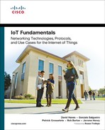
The public–private partnership shown in Figure 15-1 is an ecosystem. This means that the success of the partnership depends on both sides participating. A large part of this ecosystem is the ability to be connected with each other through information sharing. In the example of 911 being called, information is shared across the public–private partnership. This kind of sharing is evolving to include rich information exchange between public safety agencies, NGOs, and private organizations. For example, banks, grocery stores, and shopping malls rely on the protection and support of law enforcement when a crime is committed and may be able to provide live access to floor plans or security camera feeds. A large campus or factory relies on fire and EMS to protect the people and property of the NGO when an event occurs such as an active shooter, fire, illness or injury, or chemical spill. During these incidents, the school or factory security team may send information about personnel location or facility equipment to emergency responders. In the case of a school bus, the ability for parents, transportation, and school administrators to know where every bus is and who is on each bus is becoming commonplace. Another growing area of information is social media, and the possibilities to collect information about current events from individuals, NGOs, and government agencies are growing without limits.

IoT is a common theme for the use cases mentioned previously. An important observation is that the “things” are not just traditional sensors, such as optical, acoustic, pressure, fluid velocity, humidity, thermal, proximity, position, chemical, and magnetic sensors. In addition, in the public–private partnership, there are many other sensor types to consider. For instance, every individual with a smart phone is a sensor. Every NGO with its various buildings and types of businesses is generating usable information from alarm systems, cameras, smoke and presence detectors, and other various sensors. Even government agencies, their vehicles, and their personnel are adding to the wealth of the IoT through things such as smart parking meters, intelligent street lighting, next-generation transportation systems, and connected vehicles. As the IoT grows, the impact of information exchange on public safety and the public–private partnership will expand exponentially. As a result of this expanding partnership, many new innovations and use cases will appear, leveraging new data sources and sensor types, and driving the need to better store, analyze, and share information.
Public Safety Adoption of Technology and the IoT
Public safety has a history of embracing technology to support its mission. In the last half of nineteenth century, inventors such as Samuel Morse, Alexander Graham Bell, Thomas Edison, and Guglielmo Marconi invented new capabilities such as Morse code, the telegraph, the telephone, the radio, and the wireless transmission and reception of information through electromagnetic waves. By 1870, US police departments were using telephones. By the 1880s, call boxes appeared in major cities to allow the public to communicate with law enforcement. Today, the use of telephony and 911 emergency dialing to reach the nearest public safety answering point (PSAP) are common in the United States and introduced to children at the elementary school level.
In addition to telephony, radio has become an integral part of public safety. In the 1920s, police departments in Detroit, Michigan, and Bayonne, New Jersey, were experimenting with the technology, shortly after its general availability. By 1934, there were 194 municipal police systems and 58 state police radio stations serving more than 5000 radio-equipped cars. As portability of these radios became practical due to the invention of the transistor, public safety continued the adoption process. By the late 1980s, it was commonplace for every police officer to have both a vehicle-mounted land mobile radio (LMR) and a handheld portable radio. These LMR devices are almost always run on a government-owned and -operated private infrastructure that is built to public safety–grade standards for mission-critical communications.
As computers and data networks became available in the 1990s, public safety agencies began to also adopt these technologies. The ability to communicate using a mobile data terminal (MDT) or notebook computer along with a wireless data network offered major improvements in efficiency and situational awareness. A vehicle-mounted computer enables applications such as computer-aided dispatch (CAD), record management systems (RMS) access, license plate recognition (LPR), in-car video recording, and automated vehicle location (AVL).
These computers were initially connected to the department’s LMR data system, if available, with rates of up to 19.2 Kbps. Another option was to use commercial cellular services, with 1G or 2G cellular data. Today, 3G and 4G cellular services are commonplace and provide high-speed data connectivity between police, fire, EMS, school buses, and other vehicles. A major difference to consider between LMR voice and commercial cellular is that the LMR voice is built to mission-critical standards for availability and is private. The commercial cellular service is built on lower standards of availability and is not dedicated to public safety. However, changes are afoot, as discussed later in this chapter.
The trend for public safety to be early adopters of new technology is visible through the examples provided in this chapter. IoT will continue to accelerate this adoption trend. For example, in some countries, airport authorities already associate a person’s identity (passport data) to their picture (collected through security cameras at check-in counters) and a picture of their suitcase. As a person lands in another city, this data set is combined with shape and face recognition and displayed on the customs agent’s monitor as the person approaches the counter. Many law enforcement agencies use drones to monitor crowds. Onboard cameras can include data processing ability to detect crowd density and unusual movements in order to alert officers when needed, based on their relative location to the detected unusual movement.
An IoT Blueprint for Public Safety
A consequence of the rapid technology adoption and the multiplicity of data sources and processing logics is that IoT for public services cannot be limited to a strict set of use cases. Therefore, designing for IoT in the public safety space implies grouping objects and data types into actionable categories. Each use case and each environment may have a unique architecture. Above all these architectures, IoT for public safety needs a general framework. The IoT blueprint shown in Figure 15-2 provides a framework for the public safety enterprise. This framework is extensible to describe an IoT framework for almost any public safety agency, large or small. By using this blueprint as a guide, you can correlate and align new objects, applications of IoT, or requirements with the overall design.

Mission Continuum
At the top of the blueprint, six types of communication locations and devices ensure the mission continuum:
![]() Remote offices and fixed sites: These are fixed locations, such as a police precinct, a fire station, a vehicle depot, a school building, or an administrative building that supports the mission. This is where traditional networking solutions for routing, switching, unified collaboration, security, and applications are found. These networks transport IT and OT data.
Remote offices and fixed sites: These are fixed locations, such as a police precinct, a fire station, a vehicle depot, a school building, or an administrative building that supports the mission. This is where traditional networking solutions for routing, switching, unified collaboration, security, and applications are found. These networks transport IT and OT data.
![]() Mobile command center and emergency communications sites: These are temporary locations that need to be deployable, sometimes rapidly, to provide support for incident command, specialized teams, or similar functions integral to the public safety mission. IT and OT communication for these sites can be supported by kit-based or specially designed vehicle-mounted solutions for connectivity and operation. These sites may locally process data collected from the field and/or interact with the rest of the continuum to allow for a collective situational awareness.
Mobile command center and emergency communications sites: These are temporary locations that need to be deployable, sometimes rapidly, to provide support for incident command, specialized teams, or similar functions integral to the public safety mission. IT and OT communication for these sites can be supported by kit-based or specially designed vehicle-mounted solutions for connectivity and operation. These sites may locally process data collected from the field and/or interact with the rest of the continuum to allow for a collective situational awareness.
![]() Land, air, and sea mobile vehicles: These mobile vehicle platforms require connectivity in motion. Examples are cars, trucks, buses, boats, and aircraft that support the public safety mission. These vehicles are typically equipped with multiple sensors and smart objects, such as cameras, tablets, and specialized devices. Technologies for these vehicles are designed to deal with harsh environments in which temperature, shock and vibration, and humidity can range widely. These locations also apply special attention to size, weight, and power (SWaP) requirements, which can be highly constrained.
Land, air, and sea mobile vehicles: These mobile vehicle platforms require connectivity in motion. Examples are cars, trucks, buses, boats, and aircraft that support the public safety mission. These vehicles are typically equipped with multiple sensors and smart objects, such as cameras, tablets, and specialized devices. Technologies for these vehicles are designed to deal with harsh environments in which temperature, shock and vibration, and humidity can range widely. These locations also apply special attention to size, weight, and power (SWaP) requirements, which can be highly constrained.
![]() Mobile agents and wearable communications: These locations are the field agents themselves, or their immediate environment, typically forming a personal area network (PAN). Communication solutions for these locations are handheld or wearable solutions. The previously mentioned constraints for minimized SWaP requirements are increased here to avoid burdening the individual who carries the equipment.
Mobile agents and wearable communications: These locations are the field agents themselves, or their immediate environment, typically forming a personal area network (PAN). Communication solutions for these locations are handheld or wearable solutions. The previously mentioned constraints for minimized SWaP requirements are increased here to avoid burdening the individual who carries the equipment.
![]() Citizen-to-authority services and collaboration: This is the interface where public safety and the public collaborate through a citizen-to-authority exchange. A common exchange is 911 emergency dialing and texting. Many other examples exist and are changing, allowing this exchange to be more robust, supporting rich media voice, video, and data in real-time interactions.
Citizen-to-authority services and collaboration: This is the interface where public safety and the public collaborate through a citizen-to-authority exchange. A common exchange is 911 emergency dialing and texting. Many other examples exist and are changing, allowing this exchange to be more robust, supporting rich media voice, video, and data in real-time interactions.
![]() Sensors: These are devices and things that collect information for the public safety mission. The possibilities in this category are expanding. The sensors can be static or mobile, located in the environment external to the public safety mission team, or integrated with the team equipment. The result is a sensor grid capable of collecting information that can be combined with applications, reporting, and analytics to drive situational awareness.
Sensors: These are devices and things that collect information for the public safety mission. The possibilities in this category are expanding. The sensors can be static or mobile, located in the environment external to the public safety mission team, or integrated with the team equipment. The result is a sensor grid capable of collecting information that can be combined with applications, reporting, and analytics to drive situational awareness.
Mission Fabric
Within the public safety enterprise, the mission continuum and the various platforms are interconnected by the mission fabric. The mission fabric is a dynamic and flexible concept that enables fixed and mobile platforms to remain connected. It provides a uniform seamless method of enabling the various people, processes, and things to share a common set of security policies and to access applications and resources, and it is agnostic to the physical layer transport:
![]() Security policies are important and may vary depending on the physical or logical environment of each platform. For example, in a fixed site, the physical security of these locations should be well defined and should reduce the risk of unauthorized physical access and exposure. The requirements for security policies change across the mission continuum. External influences and access increase significantly from left to right across Figure 15-2. This is because the platforms operate within the community and in some cases operate completely unattended (as in the case of remote sensors).
Security policies are important and may vary depending on the physical or logical environment of each platform. For example, in a fixed site, the physical security of these locations should be well defined and should reduce the risk of unauthorized physical access and exposure. The requirements for security policies change across the mission continuum. External influences and access increase significantly from left to right across Figure 15-2. This is because the platforms operate within the community and in some cases operate completely unattended (as in the case of remote sensors).
![]() Access to applications and resources should also be seamless across the continuum, allowing personnel anywhere in the mission to perform their duties. This ability may change as bandwidth and network availability change, but it should not exclude or prevent a uniform and continuous ability to collaborate through voice, video, and data applications.
Access to applications and resources should also be seamless across the continuum, allowing personnel anywhere in the mission to perform their duties. This ability may change as bandwidth and network availability change, but it should not exclude or prevent a uniform and continuous ability to collaborate through voice, video, and data applications.
![]() Any physical layer transport should be compatible with the mission fabric to ensure that no matter where the mission must operate, connectivity is available. This means that any modern wired or wireless technology can be supported: Ethernet, serial, SONET and DWDM fiber optics, MPLS, Wi-Fi, commercial or private cellular, point-to-point and multipoint microwave, mobile ad hoc networking, and satellite.
Any physical layer transport should be compatible with the mission fabric to ensure that no matter where the mission must operate, connectivity is available. This means that any modern wired or wireless technology can be supported: Ethernet, serial, SONET and DWDM fiber optics, MPLS, Wi-Fi, commercial or private cellular, point-to-point and multipoint microwave, mobile ad hoc networking, and satellite.
The mission fabric is the internetworking of connectivity that ties the mission continuum together into the public safety enterprise. The mission fabric must provide a seamless integration that is independent of the location characteristics (fixed or mobile platform). The mission fabric also ensures that access to resources in the cloud is uniform and agnostic to cloud type (public, private, or hybrid). In any of these configurations, the applications should have the same level of accessibility to the end users. Similarly, tools such as data collection, reporting, and analytics tools should be extensible across the public safety enterprise. For example, a team of fire safety officials should have the ability to collaborate and share critical information to their job role, regardless of where they are—in a fixed infrastructure site, at an incident command post, in a mobile response vehicle, or on foot. Similarly, as this team is interacting with sensors or the public, the ability to communicate should be seen as a seamless interconnection of all elements, without barriers, and providing appropriate means of security and policy enforcement uniformly across the fabric.
Inter-agency Collaboration
The top half of the IoT blueprint for public safety is related to internal agency and citizen-to-authority collaboration. The lower half of the blueprint addresses inter-agency interaction. This follows the concepts mentioned earlier about the public–private partnership. Many countries have various public safety agencies, such as PSAPs (public safety answering points, where emergency calls are answered), EOCs (emergency operations centers, where representatives from one or more agencies meet to coordinate their response to emergencies), fusion centers (typically intelligence centers that collect, analyze, and disseminate information to local agencies), and LMRS (land mobile radio services, which manage mission-critical voice communications across one or more local agencies). These critical elements of the public safety infrastructure are a common point of coordination and collaboration between public and private organizations. In many cases, staffing for these organizations can be shared between public servants (police, fire, EMS) and third-party personnel with other specialized skills. Having a robust interconnect for collaboration means that timely, accurate, and meaningful information can be exchanged to more precisely and efficiently direct field resources.
A common misunderstanding exists about information sharing and collaboration among public safety agencies. In many cases, the difficulties in sharing information may be a limitation of technology, but they are often instead a limitation related to the diversity of each agency’s mission and policies. For example, following the September 11, 2001 terrorist attacks, information spread that radio interoperability was a potential contributor to first responder casualties. Police units could not communicate with fire units directly by radio, ambulances could not talk with police units directly by radio, and so on. While technology could have been improved to allow first responders to communicate better, a less emphasized fact is that police, fire, and EMS personnel do not operate in the same manner and do not speak in the same operational language. Each of these organizations is trained differently, and therefore their techniques, tactics, and procedures are very different. Some post-event initial reports indicated that if these agencies could have communicated directly, lives might have been saved. In fact, later reports indicated the opposite. Connecting 100 police officers and 100 firefighters together on the same voice channel would simply have impeded their overall performance because they would not have all used the same conversational protocols. A potentially better model would be to enable a robust set of tools for voice and video collaboration, asset location tracking, and situational awareness available to middle-level supervisors and incident command staff who can speak more than one operational protocol and provide better cross-agency coordination. As IoT solutions become more pervasive in public safety, they need to be tailored to complement the agencies’ missions, particularly in terms of their existing conversation protocols, methods of operation, and tactical procedures.
Another notable observation about how public safety is changing is related to the mobile vehicle. Most public safety agencies consider the vehicle an extension of the agency’s office space. However, the systems and capabilities in these vehicles have been implemented disparately over time. Unlike a remote office, which has equipment that shares infrastructure and services, each of these systems operates like a remote access client, resulting in a divergence of the vehicle technology and increased security risks. For example, in most police cars today, the CAD/RMS-enabled laptop may have a cellular modem. The in-car video recorder may have a Wi-Fi radio and cellular modem, too. The LPR system may have a Wi-Fi radio. The AVL tracking system may work through the laptop or through the LMR mounted in the car, or it may be independent and have its own cellular connection. The result is a multiplicative effect on operational cost and difficulty to centrally and uniformly manage and secure these systems. This situation is not isolated to police vehicles and exists in fire, EMS, and school buses. A converged framework and architecture will allow operational cost reductions, increase availability and redundancy across all systems, and support a consistent security practice.
This IoT for public safety general blueprint can then be applied to the various agencies and their various operational models. Referring to the blueprint can help ensure that each individual solution and architecture fits into the larger model. This inclusion will facilitate inter-solution and inter-architecture communication and information sharing.
Going through each possible public safety agency and deployment model would require multiple chapters. Instead, the remainder of this chapter focuses on several key examples: police, firefighters, EMS, and schools using IoT solutions. The same logic and constructs are extensible to many other public safety agency environments and use cases.
Emergency Response IoT Architecture
Police, firefighters, and EMS are very different organizations. However, they have a common need from an IoT standpoint. IoT enables emergency responders to be more responsive in fulfilling their mission: protect and preserve life, property, and evidence. IoT also helps protect emergency response providers. Emergency responders (police officers, firefighters, and EMS personnel) operate in a very peculiar environment. Unlike workers in most other professions, emergency responders operate in unpredictable environments. It is expected that while protecting the public, they may incur personal risks. They also know that they cannot work independently. They must collaborate with other responders, their chain of command, and the public to perform their duty successfully. The emergency response solutions in this chapter look at a variety of IoT capabilities available to support public agency missions.
Most IoT architectures discussed in other chapters of this book are organized in a vertical fashion, from street level to the applications at the core. The case of the emergency response IoT architecture is slightly different because it is organized around mobile or static command or emergency centers. These centers need to establish communication downstream to field personnel and collect data from various sensors (from the sensors directly, from fog computing systems that may have partially processed the collected data, or from cloud applications that may provide data that has been further processed). Connectivity is therefore the first concern of this topology, and it drives the architecture of the various elements that interconnect with the command center.
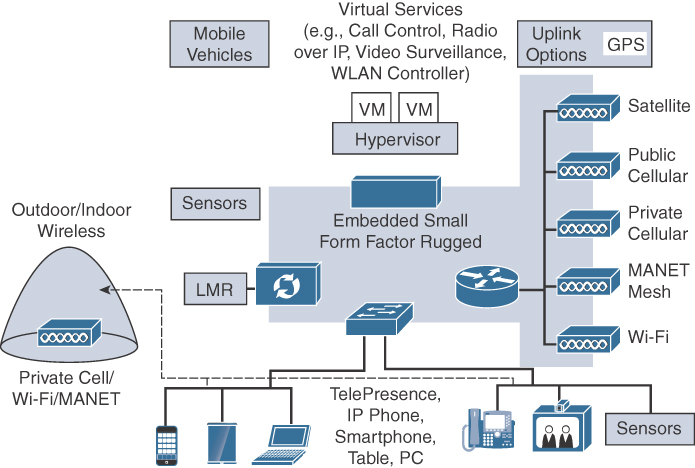
Figure 15-3 shows the various possible emergency response mobile platforms and how they are connected to the cloud via a mobility services portal. There are three common types of mobile platforms in this environment: the mobile agent of course, but also the mobile command center and the mobile vehicle.
Mobile Command Center
The mobile command center is an extension of the fixed office. The mobile command center serves as a communication hub during emergency situations, such as bomb threats, demonstrations, fires, or natural disasters, and it can also be used to conduct strategy meetings and other tactical operations. It is deployed close to the location of the emergency or on the site itself to help evaluate the emergency and also facilitate physical interaction with the local stakeholders. As a result, the requirements of the mobile command center are the same as those of a static office.
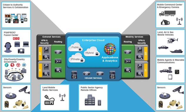
Figure 15-4 shows a typical mobile command center architecture. It is designed to provide a mobile office environment similar to the environment found in the agency’s fixed office locations. The primary difference is that the command center can operate completely independently of the enterprise or be a fully capable remote office. Most mobile command centers operate in two possible states. In the first state, they move to an area of interest, and their communication systems are very limited as they move. Once onsite, they run through a brief setup process that may include activating communications systems, deploying a mast with antennas and sensors, and extending compartments that create more internal work space. The command center is then in the second state, and fully operational. When the mission is completed, this process is reversed to allow the vehicle to move. This method of operation is referred to as communication “on-the-pause” because the vehicle must stop before becoming operational.
Network and Security Services
The mobile command center typically has sufficient space to support traditional IT equipment, including 19-inch rack mounting space. This makes it possible to use many standard products for routing, switching, wireless control, security, and compute services. Where the command center differs from the standard remote office is that all of its connectivity to the cloud is generally wireless.
The mobile vehicle architecture is based on the concept that any uplink technology should be a useful tool in reaching the enterprise cloud. This means that almost any wired or wireless technology is acceptable. For example, a wired Ethernet connection could be provided from a local source of Internet connectivity. As Figure 15-4 shows, there are many wireless options available. These can be configured through policies to support a variety of configurations such as active/standby and active/active load sharing. The ability to automatically fail over from one link technology to another is an inherent feature of this architecture and should be mandated in the chosen solution. Tools like IP service level agreements (IP SLAs), link tracking, Bidirectional Forwarding Detection (BFD), and routing protocols that can identify conditions and change the current operating configuration in real time should be selected to guarantee an always-on uplink while optimizing and balancing bandwidth and cost based on the mission requirements. Active/active load sharing can also be accomplished in a variety of ways, such as using Policy Based Routing (PBR), Performance Routing (PfR), and Gateway Load Balancing Protocol (GLBP). The result is a flexible set of tools that can allow almost any combination of wireless or wired uplink paths to be used in a highly scalable model.
The decision to use one or more wireless uplinks is usually based on local reliability, cost, performance, and availability. Satellite and 4G cellular are the most commonly used options. However, satellite connections can be expensive and can also result in large round-trip delays of 600 ms or more. When available, cellular is often preferred to satellite, because of lower cost and latency for an equivalent bandwidth. In most urban environments and their vicinity, 4G LTE cellular service is available and can provide good performance at a reasonable price, from 1 to 30 Mbps, with round-trip delays of 30 to 80 ms.
Some public safety agencies are using a unique wireless technology called MANET (mobile ad hoc network). MANET radios provide a self-forming peer-to-peer capability. When two or more MANET radios can reach each other, they can establish a high-speed Layer 2 link. These radios also allow meshing of nodes that support intermediate node hopping. This means if two nodes are too far apart but one or more intermediate nodes are available, the nodes can work together to dynamically form a multi-hop end-to-end connection. MANETs are self-forming and self-healing. Their range is flexible, as they can change frequencies to adapt to the range and link conditions (30 MHz to 5 GHz). Some of the nodes may be connected to the Internet over a fast connection (Wi-Fi or Ethernet, for example) and share their connection with the other remote nodes. MANET radios are gaining popularity in military and government use cases, and the price per radio is coming down to a point where public safety is starting to adopt the technology. As a result, the architecture in Figure 15-4 shows MANET radios being used for both uplink and client access applications.
Private cellular service is a growing concept in public safety. Many countries are pursuing major initiatives to deploy national public safety broadband networks using 4G LTE technology. These networks operate in a dedicated band, separate from the traditional service provider systems. This system ensures that public safety agencies can communicate, regardless of the condition of public commercial cellular services. In the architecture in Figure 15-4, the mobile command center could access a private cellular system as a client and use the service as an uplink.
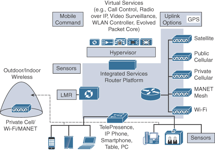
As a part of the public safety enterprise, a mobile command center must provide secure communications and support data privacy similar to that of the agency’s remote offices. Because the mobile command center uses similar equipment to that in the remote offices, the same security policies and features can be implemented on both sides. Security in this case can be considered in two areas: physical and network security. Physical security can be addressed much as in an agency’s remote office, using access control, alarm, and video surveillance systems. A variety of physical security solutions provide standard physical access readers and door actuators, as shown in Figure 15-5. Physical access control can also include a wide variety of asset control tags, identity management solutions, and alarm panels. IP video cameras are well suited to collect video streams from around a vehicle, record the content for review and playback, and distribute video to incident area personnel.
Network security for a mobile command center should meet or exceed the policies and procedures used in agency remote offices. In the mobile command center architecture, the router is the common integration point between the vehicle and the outside world of connectivity. The router must therefore offer advanced security services (for example, advanced encryption, firewall services, threat protection, VPN) to protect data as it traverses the wireless uplinks to the enterprise. It may also be required to protect local Internet access connectivity.
Securing open Ethernet ports and wireless access is an important consideration for a mobile command center. In a mobile platform, this is especially important because the exposure of IT infrastructure to personnel outside the public safety agency is a given. Figure 15-6 provides a sample use case. A mobile command center does not have the same physical security protections as a fixed office. Any individual in range of the command center can detect the Wi-Fi network and attempt to eavesdrop or hijack or disrupt communications. A common deployment model uses a WLAN controller-based architecture, where the AP is in the command center, but the WLAN controller stays in the static office. The AP connects to the WLAN controller over the WAN uplink. User authentication occurs through the central WLAN controller and a RADIUS server. Any port on the switch in the command center is also protected with 802.1x authentication. If an access request cannot be authenticated, policies on the local switch or Wi-Fi access point can prevent access completely or limit access until authentication can be provided. This approach ensures that access to wired and wireless connections is managed uniformly and mitigates threats based on physical access to the vehicle.

While access points in the vehicle are configured to provide local service, the centralized management approach offers greater security and consistency (with the central team managing all deployed wireless systems and the local team focusing on the mission). This ensures that a common set of security policies and access designs are available across the public safety enterprise. It can also reduce end-user training requirements if the Wi-Fi infrastructure in the mobile command center is consistent with that of the fixed office environment.
A mobile command center can support authorized agency personnel and others at an incident. Many times when a command vehicle appears on the scene of an incident, it can provide assistance to other partnering agencies and the public, particularly for those who need Internet access. Leveraging the solution discussed previously, both wired and wireless connectivity can be provided to external agency personnel and to the public, using a guest network. These connections can be directed immediately to a local Internet connection or can be passed through the wide area uplink to the enterprise cloud for handling. Security features such as web filtering, virus scanning, and similar services can be applied in either configuration.
The WAN link is a common bottleneck in this type of deployment. Three key features are critical to successful operation, particularly if satellite services are used:
![]() Latency: A well-known issue with using IP applications over satellite is that when network latency exceeds 500 ms roundtrip, the TCP window size in a network flow shrinks to adapt to the latency of the network. Unfortunately, even a single satellite hop introduces a minimum delay of 550 to 600 ms of roundtrip latency. Most satellite modem providers try to address this issue by implementing a performance enhancement proxy (PEP) or similar service to dynamically inspect and change the TCP window size in network flows. Without a PEP, the available bandwidth of any satellite connection goes greatly unused, and limits the end user to very poor performance. When a PEP is available, performance is greatly improved and extremely easy to notice.
Latency: A well-known issue with using IP applications over satellite is that when network latency exceeds 500 ms roundtrip, the TCP window size in a network flow shrinks to adapt to the latency of the network. Unfortunately, even a single satellite hop introduces a minimum delay of 550 to 600 ms of roundtrip latency. Most satellite modem providers try to address this issue by implementing a performance enhancement proxy (PEP) or similar service to dynamically inspect and change the TCP window size in network flows. Without a PEP, the available bandwidth of any satellite connection goes greatly unused, and limits the end user to very poor performance. When a PEP is available, performance is greatly improved and extremely easy to notice.
![]() Encryption: However, in order to address security requirements, the router is often configured to encrypt the network traffic before it reaches the satellite modem. This prevents PEP services inside the modem from seeing the TCP traffic. In that case, a local service can be installed behind the router to provide PEP capability and compression over the WAN link, as shown in Figure 15-7.
Encryption: However, in order to address security requirements, the router is often configured to encrypt the network traffic before it reaches the satellite modem. This prevents PEP services inside the modem from seeing the TCP traffic. In that case, a local service can be installed behind the router to provide PEP capability and compression over the WAN link, as shown in Figure 15-7.

![]() Appliance or Virtual Machine: The local PEP service can be a standalone appliance, a virtual machine, or a module embedded in the router. This approach can dramatically improve performance of the WAN uplinks to allow near 100% link utilization and high compression ratios (100:1) can be achieved.
Appliance or Virtual Machine: The local PEP service can be a standalone appliance, a virtual machine, or a module embedded in the router. This approach can dramatically improve performance of the WAN uplinks to allow near 100% link utilization and high compression ratios (100:1) can be achieved.
Compute and Applications Services
A mobile command center needs to be agile and capable of supporting the dynamic nature of the mission. The compute and application services need to work interactively and seamlessly with the enterprise and incident area resources. These services also need to be self-sufficient in times when the enterprise cloud is unavailable and the mobile command center is the only available representation of an agency’s command structure in an incident. These are referred to as dependent and independent modes of operation. To support both dependent and independent operations, the mobile command center should have local compute capabilities with the ability to host virtual machines and applications. Hosting applications is possible through a dedicated server or through an embedded capability in the router, both of which are designed to support application virtualization.
The effectiveness of a mobile command center is heavily dependent on its IT and OT capabilities. Traditional IT capabilities for voice, video conferencing, and data sharing provide a foundation for the command center. OT-specific applications such as CAD, RMS, COP, fleet management, and similar tools add to this foundation and address use cases for public safety.
Local control for IT voice and video calling is at the core of collaboration. It allows a mobile command center to operate with or without a connection to the enterprise cloud. When the command center can access the enterprise cloud, services such as on-net voice and video calling can ensure security and reduce cost of operations. In independent mode, voice over IP (VoIP) services can be established between the command center and a voice service provider via an Internet connection directly. As long as at least one of the command center’s uplinks can reach the Internet, voice services can be established. This approach can be the primary method of direct inward and outbound dialing, or it can be a backup approach. Using an adaptable solution provides many flexible features. For example, a staff member can take an open workspace in the command center, log into the phone on the desk, and begin making and receiving phone calls with his or her own phone number. In this case, the desk phone uses extension mobility to assume the proper personality for the end user, allowing the person to be reached wherever he or she is located. The user can log off the phone when he or she is done so that it is available for the next user. Instant messaging, presence, and voice and video dialing from computers, smart phones, and tablets is also provided through a personal communications client application. In an operational environment where desk space and access to a physical telephone or video endpoint may be limited, having such a flexible communication tool can increase availability of personnel and reduce complexity in an incident.
Push-to-talk voice is an OT staple for public safety agencies. A mobile command center relies on access to its LMR systems to effectively interact with field personnel. A basic approach is to mount portable handheld or traditional vehicle-mounted mobile radios in the command center. This can be done at each desk or in a cabinet with remote control heads with speakers and microphones. This approach is common but has issues. In a busy environment, having many speakers blaring can raise the noise floor and can be distracting, reducing the effectiveness of the operation. Also, deciding which radios to install at each desk can be challenging because the functional role of each desk position may change based on the mission. Installing too many LMR devices or the wrong kinds can be an expensive and wasteful mistake. Using an advanced radio control system, as shown in Figure 15-8, to centrally manage the radios in a command center and dynamically distribute access to users is a scalable and flexible approach. It allows any user to access any radio in the vehicle by using a mobile client installed on an Android or Apple smart phone or tablet. Such a system can also integrate with existing radio infrastructure over IP connectivity to the enterprise. This is important because it can minimize the number of radios required onboard. It can also increase accessibility of the command center, including any local public safety resources available to that agency and any other partnering agencies.

IT teleconferencing, video conferencing, and web and white board collaboration are tools most people, including public safety, use to collaborate today. Software solutions providing this service are common in a mobile command center.
Public safety agency–specific OT applications can also be hosted and/or accessed via a mobile command center. These CAD, RMS, LMR dispatch, PSAP call management, and EOC management tools can be used during a deployment. Another application that is beginning to appear in these vehicles is called a common operating picture (COP), shown in Figure 15-9. Unlike a CAD tool, a COP is designed to display real-time tactical operations with various assets, such as people, vehicles, drones, and sensors. Most COP tools integrate with rich media such as video feeds and can direct other users of the COP to view something of interest. COPs can also support telestration—the ability to draw freehand or use polygons on a map, an image, or even a video display. A team leader can use a COP, for example, to direct field forces toward an objective. An important aspect of COP tools is that everyone across the mission sees a common picture; previous situational awareness tools allowed only the supervisor or commander to see the entire picture. Having this flexibility in a mobile command center can allow the platform to assume a variety of roles, based on the incident, such as a PSAP recovery solution, incident command post, joint operations and coordination center, or special task force mission.

Mobile Vehicles: Land, Air, and Sea
The public safety mobile vehicle architecture, shown in Figure 15-10, describes a variety of mobile platforms used in public safety. This architecture is similar to the mobile command center from the previous section but with several important distinctions. The most important distinction is that the mobile command center architecture is based on the concept of communications on the pause, or when the vehicle is parked. A mobile command center also can operate autonomously from the enterprise network and cloud services. The land, air, and sea mobile vehicles architecture is designed for communications on the move and also acts as an extension of the public safety enterprise; therefore, it is typically dependent on enterprise services such as applications. These platforms do not use wired uplink communications. They depend on wireless uplinks and peer connections as the vehicles are in motion on land, in the air, and afloat.
Another important distinction is the physical and environmental characteristics of mobile vehicles. Physically, the IoT solutions inside these vehicles are required to be self-contained, or at least provide a minimum equipment footprint. These vehicles are designed for mission objectives. For example, a fire truck or EMS vehicle has many compartments for specialized equipment. The space allocated for communications, sensors, or data processing units has to be as small as possible. Environmentally, these vehicles operate at high and low temperatures, experience shock and vibration, and are exposed to humidity, moisture, and dust. While general-purpose equipment can be used in these vehicles, the environmental conditions can greatly reduce the life of electronic equipment. Some specialized vehicles, such as aircraft or marine vessels, may mandate equipment certified for airworthiness or for use in harsh conditions. To address issues of physical and environmental requirements, public safety agencies define size, weight, and power (SWaP) specifications for onboard equipment. They also require industrial-, public safety–, or military-grade–hardening.
Network and Security Services
The land, air, and sea vehicles require routing, switching, wireless, security, and compute capabilities that can meet SWaP and hardening specifications. This network equipment needs to allow for an extended operating temperature range and many operate without internal cooling fans. The equipment must be designed to run on DC power, with wide upper and lower limits. It needs increased humidity tolerance, and some equipment is also hardened for shock and vibration. It also needs to be small and is sometimes integrated directly into the vehicle body.
The need for uplink radio flexibility and diversity in these vehicles is the same as in the mobile command center. However, the ability to carry many radios or large antennas, such as a satellite dish, may not be feasible. This limitation focuses the uplink to a more restricted set of communication media. The size, purpose, and deployment model (including the range and deployment environment) of the vehicle commonly dictates the choice of the uplink technology.
The vehicle itself may be connected to the surrounding IoT architecture through technologies like DSRC. (DSRC is covered in detail in Chapter 13, “Transportation.”) This technology enables the vehicle to get privileged access through traffic and also exchange information about the travel path or other vehicles. For example, sensors are more and more often installed at rail crossing locations. As trains travel between crossings, traffic data can be fed into the OBU through LTE. Multiple IoT systems can be leveraged to achieve this goal. Trains can communicate their position in real time to a central control system (LTE, satellite, or wired networks along the track). This information can then be exported (with APIs) to an emergency response navigation database in the cloud. Relevant parts of this information can then be pushed to each emergency vehicle, based on its travel path. At the same time, trains can signal their approach to rail crossing sensors. These sensors can relay this information to approaching vehicles (DSRC or other). For an emergency services vehicle, the result is that the onboard navigation system can factor in the speed of the emergency vehicle and the rail crossing availability to dynamically reroute the vehicle if necessary, avoiding wasting time at a closed railway crossing.
Similarly, a first responder vehicle can communicate over lower ISM frequencies (for example, 433 MHz) or DSRC with smart traffic lights to make sure to always get “green” on the way to an emergency location. This control is typically decentralized (the vehicle communicates directly with the traffic lights as it approaches; the command center does not need to coordinate the lights). While the vehicle is on its way, the headquarters team may be able to connect to the data available from around the scene of the emergency, as detailed earlier in this chapter. Then, as the vehicle approaches the location of the emergency, a subset of this data is fed into the vehicle compute system. The response team can thereby access useful data relevant to the mission, such as the number of floors of a building, floorplan, number of occupants, location of nearby fire hydrants, crime history of the location or nearby locations, data from nearby environmental sensors (for example, presence of smoke, hazardous gas). During the emergency response, smart objects can facilitate the efficiency of the response. For example, when EMS vehicles are involved, tablets are used to input a basic diagnosis, helping receiving hospitals to be ready with the right equipment and the right teams.
Physical security is also challenging for these vehicles. If a vehicle or vessel is sufficiently large, it may need to use physical security solutions like those in a mobile command center. Otherwise, physical security may be limited to the trunk of a car or an equipment locker. Video surveillance in these vehicles depends on the vehicle type and its duty. For example, police vehicles are commonly equipped with dash cameras, and many have detention area cameras and microphones. In-car video recorders place a special requirement on the vehicle architecture to avoid uploading locally recorded video over metered services such as 4G cellular. Most agencies prefer that the video be uploaded when the vehicle is in close proximity to a Wi-Fi access point at a police station or similar facility. This means the vehicle router must be application-aware and permit video upload only when Wi-Fi is available.
Network security features for mobile vehicles are mostly the same as those of a mobile command center, such as robust AES 256-bit encryption, stateful firewall inspection, and VPNs. Advanced threat protection services may be limited by the performance capability of the smaller routing platforms. In cases where threat protection is a concern, adding compute resources in the vehicle may be the best approach.
Uplink compression and optimization are critical for mobile vehicles using constrained wireless uplinks, such as cellular and satellite services. However, most land vehicles do not use satellite for uplink, unless they routinely operate outside cellular coverage. Aircraft and some larger or long-distance offshore marine vessels typically have satellite requirements.
Compute and Applications Services
Land, air, and sea vehicles have different compute and application services needs than does a mobile command center. The mobile vehicles are more focused on the execution of a specific, and typically short-term, mission. A major portion of the mission is to work collaboratively with the enterprise, which means communications and applications need to be shared. There are times, though, when the focus shifts to a specific incident. In this case, it is understood that collaboration is reduced and applications are subject to availability within the incident area. The result is that most mobile vehicles carry a minimum set of applications locally—mostly client capabilities—and depend on the enterprise or the command center for hosting the applications. A good example of this logic is the push-to-talk voice service.
Vehicle-mounted mobile and handheld portable LMR devices have been a long-standing primary method of public safety communication. These devices use the communication infrastructure to talk over long distances. The infrastructure includes base stations, interconnections, and a central switching capability much like the enterprise cloud model provides. Emergency personnel also communicate locally with one another in a peer-to-peer fashion, referred to as line-of-sight, talk-around, or simplex mode. This communication is independent from the larger communication infrastructure. However, the infrastructure enables collaboration with the broader agency. In an incident, most agencies train their personnel to work in simplex mode, or at least on a tactical talk group. The primary reason for this model is efficiency. The talk-around mode eliminates any dependency on the infrastructure and limits the scope to the agents available in the immediate vicinity of the emergency scene. This model focuses communications on the incident area activities and avoids straining wide area infrastructure resources, which are always constrained in an LMR system. This model also avoids distracting the rest of the agency with local operational conversations. Communication with the agency is still possible but is limited to specific requests.
IoT has changed the push-to-talk public safety voice environment. In the 2000s, push-to-talk voice and IP were combined to provide Radio over IP (RoIP). Wireless network availability has led public safety to adopt RoIP. A key influencer is the increasing coverage and availability of commercial 4G LTE services, which now provide high-density coverage in more metro, urban, and even rural areas. Private dedicated cellular programs, such as FirstNet are also evolving to provide mission-critical–grade cellular for public safety. The applications for RoIP are also evolving, extending to soft clients and paging.
Before RoIP and networks like FirstNet can fully replace LMR, a variety of limitations must be overcome. One issue that relates to IoT is enabling both dependent and independent modes of operation for cellular communications. 3rd Generation Partnership Project (3GPP), the standards body responsible for LTE and the future cellular technologies, is working on solutions to allow cellular smart phones and similar devices to operate in an infrastructure-independent mode (that is, talk-around mode). Other issues include battery life, signaling, and application interaction.
Collaboration tools such as voice and video conferencing, instant messaging, presence, and web collaboration require access to the enterprise cloud to allow for collaboration beyond the incident area. If the applications are hosted in the enterprise cloud, collaboration is not possible without a viable uplink connection. This situation is similar to the LMR infrastructure mode for wide-area push-to-talk voice.
Public safety–specific tools like CAD, RMS, and COP are an important area of discussion for mobile vehicles, as they address mission-specific requirements of the agency. CAD and RMS, which have been around since the 1990s, help manage workflows and field personnel. They also enable field agents to run queries and reporting. These applications are client/server based, which means they have access to limited compute capability in the vehicle and depend on the uplink connection and enterprise cloud for application access and data repositories. To avoid issues with slow or intermittent connectivity, legacy CAD and RMS applications required the use of session persistence software to maintain the application connection. This software also provided VPN services to secure the applications. Next-generation CAD and RMS applications are designed for the mobile workforce; they do not suffer session persistence issues, and they support embedded security to minimize the dependency on VPN software.
A COP is a next-generation application for public safety that provides a real-time view into an incident area environment. It can function in client/server mode, where one or more servers collect multicast events from clients around the network and distribute them to all other clients. It can also operate in an incident area mode, in which case it is independent of the larger enterprise. This latter case may be a result of limited network connectivity or by design, to control the scope of collaboration and information sharing. This incident area mode maps well to the mobile vehicle architecture. Recall that a vehicle can use a variety of uplinks and peer-to-peer MANET radios. This design allows the router to dynamically manage the links and allows the COP to function in either client/server or peer-to-peer mode.
The compute resources embedded inside the vehicle platform are sized according to the application’s requirements. Many of the applications already discussed for the vehicle platform are typically run on a laptop, smart phone, tablet, or similar client compute device. In some new deployment models, the client computer has limited performance and simply provides remote keyboard, video, and mouse (KVM) functions or lightweight virtual desktop capabilities. This approach limits the configuration and administrative burden of the client computer in the vehicle, and moves the processing to the enterprise cloud.
In-car video management has been available for public safety and other fleet vehicles for some time. In many cases, these solutions are independent from other equipment on the vehicle. By embedding a video management system in the in-vehicle platform, the system can be centrally managed and operated as part of the overall enterprise. Telematics is another example of this integration concept; it provides the ability to monitor and control the vehicle from the enterprise. One use case is connecting to the vehicle’s onboard diagnostics (OBD) interface. An OBD interface is available in all modern vehicles. Tapping into the OBD interface allows vehicle operational characteristics to be collected and reported, including identifying maintenance needs, driving patterns, and brake status. The vehicle systems (for example, door locks) can also be controlled remotely. Emergency lights, siren, weapons locker, and other features of the vehicle can also be monitored. In the past, sensor events and events monitored via the OBD interface were streamed back to the enterprise in real time. Information could be delayed or lost in poor coverage areas. Today, the vehicle platform includes fog computing agents and lightweight microservices that run within the vehicle. The fog agents can collect, store, process, and synthesize data and then stream either the raw or synthesized data back to the enterprise. Data can also be shared with incident area peers. The fog agent is particularly useful when the vehicle is in a poor coverage area. The agent can detect the network conditions and hold the data until connectivity is restored.
IoT provides many useful and important benefits to public safety and emergency response. The mobile command center and land, air, and sea mobile vehicle platforms are built on a common reference design. The factors that influence these platforms are related to their operational, physical, and environment requirements. The operational requirements help identify the level of capability available. The capabilities change depending on whether the vehicle is connected to or disconnected from the enterprise network and depending on whether the responders are functioning in a wide area or incident area capacity. Physical requirements relate to the SWaP footprint of the equipment and to its integration into the vehicle. Environmental requirements identify the operational thresholds for hardening. As these solutions are applied to a specific public safety agency, options for network, security, compute, and application services need to be considered to meet each agency’s specific needs.
IoT Public Safety Information Processing
IoT is a network of physical objects that can sense and communicate data. Processing this data is a key part of IoT, as detailed in Chapter 7, “Data and Analytics for IoT.” In the case of public safety, specific smart objects facilitate the emergency response. For example, smoke detectors and fire alarms are well-known objects. With IoT, these objects can be connected to the Internet and trigger an alarm to the closest fire department. Similarly, these sensors can communicate with one another. Such communication allows a fire alarm to be triggered with a specific sound or ring pattern if a neighboring house or building is on fire, allowing proactive measures to be taken.
In schools, universities, and crime-sensitive neighborhoods, gunshot detectors are often deployed. These sensors process sounds to search for the specific pattern of a gunshot sound. If this pattern is detected, an alarm is automatically sent to the closest police station through a wired or wireless communications link. The reduction in the incident detection time in turn reduces the overall response time.
Video processing is now a common application in public safety. New machine learning algorithms increase facial recognition success rates, and processing images from crime scenes has become a common IoT application. Real-time video is also commonly used to allow for remote specialists’ assistance in multiple emergency scenarios, including those involving accidents, specific hazardous materials, and automatic crowd movement pattern analysis. Video is also used for public safety cases that are not related to emergency situations to improve efficiency and reduce risks related to transportation. For example, video arraignment and remote court appearance applications have become common, limiting the cost and risk of transporting convicts. Remote language interpretation is also assisting emergency workers when interacting with citizens speaking a different language.
Big data is also being leveraged in public safety. For example, crime data can be analyzed in detail to provide a prospective view on crime potentiality. Big data systems cannot predict the future. However, these tools can analyze past crime characteristics and map criminal behavior patterns to infer the probability of future criminal activity. Figure 15-11 shows an example.
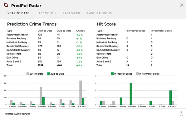
Police forces can use this information to deploy the right number of officers in the right locations to prevent crimes from occurring.
The same logic is used by many other public safety agencies. For example, fire department headquarters use machine learning to cross-analyze data and predict fires. Information can include obvious elements such as fire history or building material. Proactive action can then be taken to avoid fires before fire conditions arise.
School Bus Safety
Public safety spans beyond emergency services and includes any field where the general public and their safety is at stake. Today, IoT is being applied to school buses to provide new capabilities and insights to transportation directors, parents, principals, and students. A large portion of the architecture directly involves the safety of the students. In addition, buses now provide services for the onboard students to be connected and work on homework assignments. In essence, the school bus becomes an extension of the network that exists on the school campus. Figure 15-12 shows a high-level diagram of the architecture and the services offered.

Bus Location and Student Onboarding/Offboarding
One large problem that parents and school personnel face every day is knowing where a bus is located and whether a student is on the bus. This can become an even larger problem in school districts that are spread over large geographic areas and have a bus depot where students must change buses. A school transportation director’s day is often not completed until every student is accounted for and all the buses have returned to the bus yards. In many situations, a parent, expecting his or her child to be at home, calls the transportation office looking for a student. Without the aid of IoT, transportation office personnel have to make phone or radio calls to determine whether a student is on the bus. In many cases, the bus driver may not know for sure (perhaps it is a substitute driver who doesn’t know all the students). There’s a good chance that the student never boarded the bus that day (maybe the student stayed at school for after-school learning or activities), or perhaps the student disembarked the bus at a friend’s house. With the assistance of IoT, the transportation director can know, in real time, the exact location of a bus, which students are on the bus, and where students exited or entered the bus. Now, when a parent calls looking for his or her child, the transportation director can say, “Your child exited the bus at the corner of Smith and Jones Streets at 3:30 p.m.” Or, perhaps the transportation director can say, “Your child did not get on the bus today.”
Simply knowing where buses are located can be of great help to transportation directors. It is especially useful when a school activity bus has traveled a long distance from the school. In the event of a safety-related incident, the transportation director can know exactly where to direct emergency responders. The transportation director can also know approximately when to expect a bus to reach a given location (perhaps the bus yard) and can be alerted if the bus has traveled outside a previously defined boundary; this is called geo-fencing. Figure 15-13 shows an example of geo-fencing in which the area overlaid in red represents the locations where a bus might be found during a normal day. If the bus travels outside this area, school personnel are alerted.
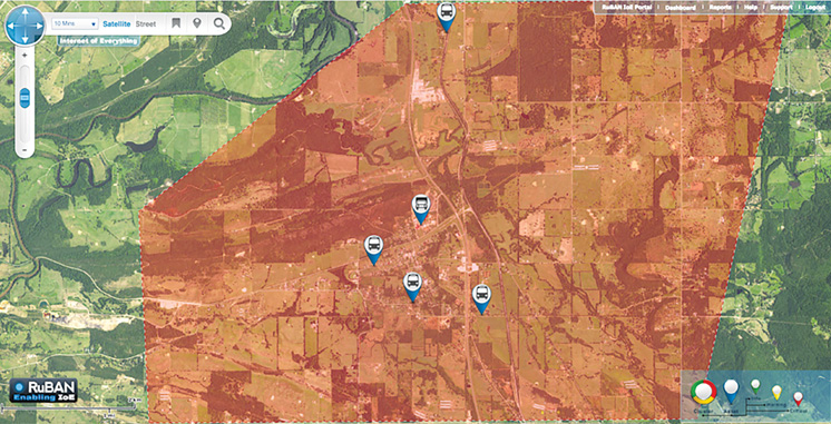
Driver Behavior Reporting
Another advantage of having location and telematics information is to monitor bus driver behavior. For instance, if a bus driver exceeds a safe speed, the transportation director can be alerted. This alert can occur in real time or can be recorded in a database. At one deployment, a concerned parent called the school and reported that he had been driving behind an activity bus a few days prior, and the bus had been driving at an unsafe speed. School personnel were able to review the entire history of the bus route and found that the bus was, indeed, traveling too fast. In addition, school personnel were able to review historical video footage from the bus to determine if, perhaps, there was some type of distraction on the bus that could explain the excessive speed. Figure 15-14 shows an example of the GPS replay function.

Figure 15-15 shows another example of driver behavior reporting. This type of report is useful for determining if a given driver consistently doesn’t spend enough time at a bus stop for boarding students to be safely seated or if a given driver achieves unacceptable fuel mileage, perhaps due to spending an excessive amount of time idling during a route. This type of reporting can result in safer driving as well as economic savings.
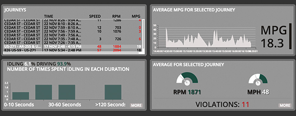
Diagnostic Reporting
In many cases, an issue is reported on the OBD port long before any obvious symptoms (such as low fuel mileage or a check engine light) are apparent. By harvesting this data from the bus, maintenance personnel can be alerted to potential issues, automatically, without having to physically travel to and inspect the bus.
Video Surveillance
One of the most widely used features of the school bus safety solution is video surveillance. Video surveillance can be used to monitor student safety on the bus and also to record what happens outside the bus in the event of an accident or a driver illegally passing a stopped school bus. A common case is a parent calling a school to report that her child witnessed bullying behavior, a fight, or a weapon on the bus. School personnel can watch forensic video from the day/time in question to determine what actually occurred. The video is also available for live viewing by school personnel. So, if a bus driver radios to the transportation director that students are fighting on the bus, the transportation director can view the live video and determine an appropriate course of action (for example, request emergency personnel). Figure 15-16 and Figure 15-17 show examples of live and recorded video viewing.

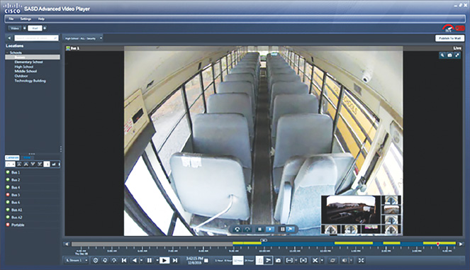
In many countries, drivers are not allowed to pass a stopped school bus, as children may be walking around the bus or crossing the road without paying careful attention to possible traffic. For example, in 2014, the state of North Carolina found that about 3000 drivers per day passed a stopped school bus.1 This creates an obvious safety concern for students. It is very difficult to identify and prosecute offenders, and thus it is difficult to create an effective deterrent. For instance, in 2014, even though the offense happened thousands of times per day, only 1300 cases went to court in the entire year in North Carolina, and only 29% of those drivers were found guilty. One way to improve this situation is to install an external camera (or cameras) to catch drivers that pass the stopped school bus. Video clips that capture identifying characteristics of the offending vehicle can be provided to law enforcement personnel. The speed of the bus, turn signal, and brake application data can also be overlaid on the video for accident investigation purposes. In a common deployment, due to the high bandwidth required for high-quality video capable of capturing license plate numbers, the video is stored locally on the bus camera and then uploaded over Wi-Fi when the bus is back in the bus yard.
Student Wi-Fi
Some students are on a bus for over two hours per day, which can be valuable studying time. Wi-Fi can be provided to allow students to do homework on the bus or to simply occupy them to help prevent behavioral issues. It is common for all student Wi-Fi traffic to travel back to the school network, where the school system’s Internet access policy and filtering can be applied. An access point is deployed on the bus, and a small router relays the queries to a cellular data connection. In some cases, a small compute and storage system can cache frequently accessed resources, such as the school website and teacher assignment pages.
Push-to-Talk Communication
Voice communication between school personnel and bus drivers is becoming a common use case. Soft mobile clients allow a smart phone to perform push-to-talk voice communications. In the school bus application, the school can either provide smart phone or tablet devices to the bus drivers or can request that the bus drivers install an application on personal devices. In either case, the device attaches to the Wi-Fi network in the bus, thus avoiding the need to use cellular data on the smart phone device.
School Bus Safety Network Architecture
Figure 15-18 shows a high-level network diagram of the architecture for a connected school bus. This diagram maps the use cases and services discussed in the previous sections to an actual deployment.
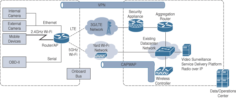
In this architecture, all services are hosted in the data/operations center. A Wi-Fi network in the bus yard is created using ruggedized, outdoor access points. The same wireless LAN controller that manages the school’s traditional Wi-Fi network can manage these access points as well.
Data from the bus to the data/operations center travels over 5 GHz Wi-Fi if it is available—for example, if the bus is on campus in the bus yard. If Wi-Fi is not available, data travels, encrypted, over a commercial carrier’s cellular network.
Onboard the bus, a router handles all edge network connectivity functions, as well as a fog computing function. It offers 2.4 GHz Wi-Fi onboard the bus (as an access point) and allows for connection to the bus yard’s Wi-Fi as a workgroup bridge (WGB), using the 5 GHz band. The router also provides cellular connectivity and includes Ethernet ports for connecting cameras and other devices. The router also performs data encryption over cellular between the bus and the operations center.
Video cameras inside and outside the bus stream video to a media server located in the data/operations center. In some deployments, the video does not transmit over LTE all the time but is stored locally on the camera and then offloaded over Wi-Fi when the bus returns to the bus yard.
Diagnostic data from the bus is provided by the bus’s onboard diagnostic port. A small software client runs inside the router to interpret the data and send relevant information to the server in the data/operations center.
Summary
While public safety covers a very broad spectrum as it relates to the IoT, a common thread forms the foundation for almost all use cases, from first responders, fire fighters, police, and school buses. In all cases, data is being gathered from sensors, transmitted over a secure network, processed and analyzed, visualized, and shared in real time (or near real time). One common requirement is the ability to process data locally and define zones where data needs to be shared among members of a field response group. At the same time, part of the data also needs to be relayed to a central command center to facilitate the overall interaction between different emergency response services. Voice and video collaboration are core tools to enable rich communication and information sharing between emergency responders. They give involved parties increased situational awareness, which helps lead to a faster, more coordinated, and safer response.
At the same time, multiple sensors are improving awareness and response efficiency. Interaction with sensors carried by emergency responders, embedded in their vehicles or integrated into the surrounding environments, extend the emergency responders’ awareness and also allow response teams to respond to emergencies at a larger scale, improving their response times through traffic light control, collecting faster and better information through access to emergency area environmental sensors, and reacting faster through the support of machine-learned movement patterns identified in a crowd.
Reference
1. C. Browder, In North Carolina, Few Drivers Found Guilty of Passing School Buses, August 24, 2015, www.wral.com/in-nc-few-drivers-found-guilty-of-passing-school-buses/14851534/.