Chapter 4. Connecting Smart Objects
IoT devices and sensors must be connected to the network for their data to be utilized. In addition to the wide range of sensors, actuators, and smart objects that make up IoT, there are also a number of different protocols used to connect them. This chapter takes a look at the characteristics and communications criteria that are important for the technologies that smart objects employ for their connectivity, along with a deeper dive into some of the major technologies being deployed today.
Two main sections divide this chapter. The first main section, “Communications Criteria,” describes the characteristics and attributes you should consider when selecting and dealing with connecting smart objects. The various technologies used for connecting sensors can differ greatly depending on the criteria used to analyze them. The following subsections look closely at these criteria:
![]() Range: This section examines the importance of signal propagation and distance.
Range: This section examines the importance of signal propagation and distance.
![]() Frequency Bands: This section describes licensed and unlicensed spectrum, including sub-GHz frequencies.
Frequency Bands: This section describes licensed and unlicensed spectrum, including sub-GHz frequencies.
![]() Power Consumption: This section discusses the considerations required for devices connected to a stable power source compared to those that are battery powered.
Power Consumption: This section discusses the considerations required for devices connected to a stable power source compared to those that are battery powered.
![]() Topology: This section highlights the various layouts that may be supported for connecting multiple smart objects.
Topology: This section highlights the various layouts that may be supported for connecting multiple smart objects.
![]() Constrained Devices: This section details the limitations of certain smart objects from a connectivity perspective.
Constrained Devices: This section details the limitations of certain smart objects from a connectivity perspective.
![]() Constrained-Node Networks: This section highlights the challenges that are often encountered with networks connecting smart objects.
Constrained-Node Networks: This section highlights the challenges that are often encountered with networks connecting smart objects.
The second main section of this chapter, “IoT Access Technologies,” provides an in-depth look at some of the technologies that are considered when connecting smart objects. Currently, the number of technologies connecting smart objects is quite extensive, but you should expect consolidation, with certain protocols eventually winning out over others in the various IoT market segments. This section intentionally limits the discussion of technologies for connecting sensors to the ones that seem to be most promising going forward in the IoT marketplace. Other technologies are mentioned in context when applicable. The following subsections cover technologies for connecting smart objects:
![]() IEEE 802.15.4: This section highlights IEEE 802.15.4, an older but foundational wireless protocol for connecting smart objects.
IEEE 802.15.4: This section highlights IEEE 802.15.4, an older but foundational wireless protocol for connecting smart objects.
![]() IEEE 802.15.4g and IEEE 802.15.4e: This section discusses improvements to 802.15.4 that are targeted to utilities and smart cities deployments.
IEEE 802.15.4g and IEEE 802.15.4e: This section discusses improvements to 802.15.4 that are targeted to utilities and smart cities deployments.
![]() IEEE 1901.2a: This section discusses IEEE 1901.2a, which is a technology for connecting smart objects over power lines.
IEEE 1901.2a: This section discusses IEEE 1901.2a, which is a technology for connecting smart objects over power lines.
![]() IEEE 802.11ah: This section discusses IEEE 802.11ah, a technology built on the well-known 802.11 Wi-Fi standards that is specifically for smart objects.
IEEE 802.11ah: This section discusses IEEE 802.11ah, a technology built on the well-known 802.11 Wi-Fi standards that is specifically for smart objects.
![]() LoRaWAN: This section discusses LoRaWAN, a scalable technology designed for longer distances with low power requirements in the unlicensed spectrum.
LoRaWAN: This section discusses LoRaWAN, a scalable technology designed for longer distances with low power requirements in the unlicensed spectrum.
![]() NB-IoT and Other LTE Variations: This section discusses NB-IoT and other LTE variations, which are often the choice of mobile service providers looking to connect smart objects over longer distances in the licensed spectrum.
NB-IoT and Other LTE Variations: This section discusses NB-IoT and other LTE variations, which are often the choice of mobile service providers looking to connect smart objects over longer distances in the licensed spectrum.
This chapter covers quite a few fundamental IoT technologies and is critical for truly understanding how smart objects handle data transport to and from the network. We encourage you to pay special attention to the protocols and technologies discussed here because they are applied and referenced in many of the other chapters of this book.
Communications Criteria
In the world of connecting “things,” a large number of wired and wireless access technologies are available or under development. Before reviewing some of these access technologies, it is important to talk about the criteria to use in evaluating them for various use cases and system solutions.
Wireless communication is prevalent in the world of smart object connectivity, mainly because it eases deployment and allows smart objects to be mobile, changing location without losing connectivity. The following sections take this into account as they discuss various criteria. In addition, wired connectivity considerations are mentioned when applicable.
Range
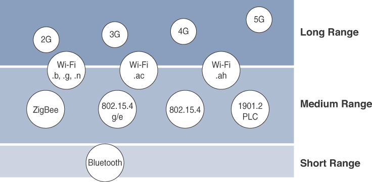
How far does the signal need to be propagated? That is, what will be the area of coverage for a selected wireless technology? Should indoor versus outdoor deployments be differentiated? Very often, these are the first questions asked when discussing wired and wireless access technologies. The simplest approach to answering these types of questions is to categorize these technologies as shown in Figure 4-1, breaking them down into the following ranges:
Note
Figure 4-1 focuses on the IoT technologies discussed in this chapter. To avoid adding too much confusion by talking about all of the multitude of IoT technologies in the market today, this chapter discusses only the ones that appear to have the strongest foothold.
![]() Short range: The classical wired example is a serial cable. Wireless short-range technologies are often considered as an alternative to a serial cable, supporting tens of meters of maximum distance between two devices. Examples of short-range wireless technologies are IEEE 802.15.1 Bluetooth and IEEE 802.15.7 Visible Light Communications (VLC). These short-range communication methods are found in only a minority of IoT installations. In some cases, they are not mature enough for production deployment. For more information on these IEEE examples, see http://standards.ieee.org/about/get/802/802.15.html.
Short range: The classical wired example is a serial cable. Wireless short-range technologies are often considered as an alternative to a serial cable, supporting tens of meters of maximum distance between two devices. Examples of short-range wireless technologies are IEEE 802.15.1 Bluetooth and IEEE 802.15.7 Visible Light Communications (VLC). These short-range communication methods are found in only a minority of IoT installations. In some cases, they are not mature enough for production deployment. For more information on these IEEE examples, see http://standards.ieee.org/about/get/802/802.15.html.
![]() Medium range: This range is the main category of IoT access technologies. In the range of tens to hundreds of meters, many specifications and implementations are available. The maximum distance is generally less than 1 mile between two devices, although RF technologies do not have real maximum distances defined, as long as the radio signal is transmitted and received in the scope of the applicable specification. Examples of medium-range wireless technologies include IEEE 802.11 Wi-Fi, IEEE 802.15.4, and 802.15.4g WPAN. Wired technologies such as IEEE 802.3 Ethernet and IEEE 1901.2 Narrowband Power Line Communications (PLC) may also be classified as medium range, depending on their physical media characteristics. (All the medium-range protocols just mentioned are covered in more detail later in this chapter.)
Medium range: This range is the main category of IoT access technologies. In the range of tens to hundreds of meters, many specifications and implementations are available. The maximum distance is generally less than 1 mile between two devices, although RF technologies do not have real maximum distances defined, as long as the radio signal is transmitted and received in the scope of the applicable specification. Examples of medium-range wireless technologies include IEEE 802.11 Wi-Fi, IEEE 802.15.4, and 802.15.4g WPAN. Wired technologies such as IEEE 802.3 Ethernet and IEEE 1901.2 Narrowband Power Line Communications (PLC) may also be classified as medium range, depending on their physical media characteristics. (All the medium-range protocols just mentioned are covered in more detail later in this chapter.)
![]() Long range: Distances greater than 1 mile between two devices require long-range technologies. Wireless examples are cellular (2G, 3G, 4G) and some applications of outdoor IEEE 802.11 Wi-Fi and Low-Power Wide-Area (LPWA) technologies. LPWA communications have the ability to communicate over a large area without consuming much power. These technologies are therefore ideal for battery-powered IoT sensors. (LPWA and the other examples just mentioned are discussed in more detail later in this chapter.) Found mainly in industrial networks, IEEE 802.3 over optical fiber and IEEE 1901 Broadband Power Line Communications are classified as long range but are not really considered IoT access technologies. For more information on these standards, see http://standards.ieee.org/about/get/802/802.3.htmlandhttps://standards.ieee.org/findstds/standard/1901-2010.html.
Long range: Distances greater than 1 mile between two devices require long-range technologies. Wireless examples are cellular (2G, 3G, 4G) and some applications of outdoor IEEE 802.11 Wi-Fi and Low-Power Wide-Area (LPWA) technologies. LPWA communications have the ability to communicate over a large area without consuming much power. These technologies are therefore ideal for battery-powered IoT sensors. (LPWA and the other examples just mentioned are discussed in more detail later in this chapter.) Found mainly in industrial networks, IEEE 802.3 over optical fiber and IEEE 1901 Broadband Power Line Communications are classified as long range but are not really considered IoT access technologies. For more information on these standards, see http://standards.ieee.org/about/get/802/802.3.htmlandhttps://standards.ieee.org/findstds/standard/1901-2010.html.
For wireless deployments, the maximum coverage, as expressed in specifications or product descriptions, is often derived from optimal estimated conditions. In the real world, you should perform proper radio planning using the appropriate tools, followed by a field radio survey to better understand the actual conditions over a given area. You also need to consider environmental factors, such as interference and noise, and specific product characteristics such as antenna design and transmit power. Finally, you should be aware of potential landscape and topology changes in the field, such as new buildings, that may interfere with signal transmission.
Frequency Bands
Radio spectrum is regulated by countries and/or organizations, such as the International Telecommunication Union (ITU) and the Federal Communications Commission (FCC). These groups define the regulations and transmission requirements for various frequency bands. For example, portions of the spectrum are allocated to types of telecommunications such as radio, television, military, and so on.
Around the world, the spectrum for various communications uses is often viewed as a critical resource. For example, you can see the value of these frequencies by examining the cost that mobile operators pay for licenses in the cellular spectrum.
Focusing on IoT access technologies, the frequency bands leveraged by wireless communications are split between licensed and unlicensed bands. Licensed spectrum is generally applicable to IoT long-range access technologies and allocated to communications infrastructures deployed by services providers, public services (for example, first responders, military), broadcasters, and utilities.
An important consideration for IoT access infrastructures that wish to utilize licensed spectrum is that users must subscribe to services when connecting their IoT devices. This adds more complexity to a deployment involving large numbers of sensors and other IoT devices, but in exchange for the subscription fee, the network operator can guarantee the exclusivity of the frequency usage over the target area and can therefore sell a better guarantee of service.
Improvements have been made in handling the complexity that is inherent when deploying large numbers of devices in the licensed spectrum. Thanks to the development of IoT platforms, such as the Cisco Jasper Control Center, automating the provisioning, deployment, and management of large numbers of devices has become much easier. Examples of licensed spectrum commonly used for IoT access are cellular, WiMAX, and Narrowband IoT (NB-IoT) technologies.
Note
Exceptions exist in the licensed spectrum. For example, the Digital Enhanced Cordless Telecommunications (DECT) wireless technology operates in licensed bands centered on 1.9 GHz, but no royalty fees apply. Therefore, DECT Ultra Low Energy (ULE) is defined as an IoT wireless communication standard in the licensed spectrum, but it does not require a service provider.
The ITU has also defined unlicensed spectrum for the industrial, scientific, and medical (ISM) portions of the radio bands. These frequencies are used in many communications technologies for short-range devices (SRDs). Unlicensed means that no guarantees or protections are offered in the ISM bands for device communications. For IoT access, these are the most well-known ISM bands:
![]() 2.4 GHz band as used by IEEE 802.11b/g/n Wi-Fi
2.4 GHz band as used by IEEE 802.11b/g/n Wi-Fi
![]() IEEE 802.15.1 Bluetooth
IEEE 802.15.1 Bluetooth
![]() IEEE 802.15.4 WPAN
IEEE 802.15.4 WPAN
Note
The low range of IEEE 802.15.1 Bluetooth limits its usefulness in most IoT deployments.
An unlicensed band, such as those in the ISM range of frequencies, is not unregulated. National and regional regulations exist for each of the allocated frequency bands (much as with the licensed bands). These regulations mandate device compliance on parameters such as transmit power, duty cycle and dwell time, channel bandwidth, and channel hopping.
Unlicensed spectrum is usually simpler to deploy than licensed because it does not require a service provider. However, it can suffer from more interference because other devices may be competing for the same frequency in a specific area. This becomes a key element in decisions for IoT deployments. Should an IoT infrastructure utilize unlicensed spectrum available for private networks or licensed frequencies that are dependent on a service provider? Various LPWA technologies are taking on a greater importance when it comes to answering this question. In addition to meeting low power requirements, LPWA communications are able to cover long distances that in the past required the licensed bands offered by service providers for cellular devices.
Some communications within the ISM bands operate in the sub-GHz range. Sub-GHz bands are used by protocols such as IEEE 802.15.4, 802.15.4g, and 802.11ah, and LPWA technologies such as LoRa and Sigfox. (All these technologies are discussed in more detail later in this chapter.)
The frequency of transmission directly impacts how a signal propagates and its practical maximum range. (Range and its importance to IoT access are discussed earlier in this chapter.) Either for indoor or outdoor deployments, the sub-GHz frequency bands allow greater distances between devices. These bands have a better ability than the 2.4 GHz ISM band to penetrate building infrastructures or go around obstacles, while keeping the transmit power within regulation.
The disadvantage of sub-GHz frequency bands is their lower rate of data delivery compared to higher frequencies. However, most IoT sensors do not need to send data at high rates. Therefore, the lower transmission speeds of sub-GHz technologies are usually not a concern for IoT sensor deployments.
For example, in most European countries, the 169 MHz band is often considered best suited for wireless water and gas metering applications. This is due to its good deep building basement signal penetration. In addition, the low data rate of this frequency matches the low volume of data that needs to be transmitted.
Several sub-GHz ranges have been defined in the ISM band. The most well-known ranges are centered on 169 MHz, 433 MHz, 868 MHz, and 915 MHz. However, most IoT access technologies tend to focus on the two sub-GHz frequency regions around 868 MHz and 915 MHz. These main bands are commonly found throughout the world and are applicable to nearly all countries.
Note
Countries may also specify other unlicensed bands. For example, China has provisioned the 779–787 MHz spectrum as documented in the LoRaWAN 1.0 specifications and IEEE 802.15.4g standard.
The European Conference of Postal and Telecommunications Administrations (CEPT), in the European Radiocommunications Committee (ERC) Recommendation 70-03, defines the 868 MHz frequency band. CEPT was established in 1959 as a coordinating body for European state telecommunications and postal organizations. European countries generally apply Recommendation 70-03 to their national telecommunications regulations, but the 868 MHz definition is also applicable to regions and countries outside Europe. For example, India, the Middle East, Africa, and Russia have adopted the CEPT definitions, some of them making minor revisions. Recommendation 70-03 mostly characterizes the use of the 863–870 MHz band, the allowed transmit power, or EIRP (effective isotropic radiated power), and duty cycle (that is, the percentage of time a device can be active in transmission). EIRP is the amount of power that an antenna would emit to produce the peak power density observed in the direction of maximum antenna gain. The 868 MHz band is applicable to IoT access technologies such as IEEE 802.15.4 and 802.15.4g, 802.11ah, and LoRaWAN. (These protocols are covered later in this chapter.)
In the latest version of ERC Recommendation 70-03 (from May 2015), CEPT introduced the new frequency band 870–876 MHz. This band is relevant to IoT wireless access solutions. However, its adoption in local country regulations is still an ongoing process. This new band is referenced in the IEEE 802.15.4v draft and the Wi-SUN 1.0 regional PHY layer parameters. (Wi-SUN 1.0 is discussed later in this chapter.)
Centered on 915 MHz, the 902–928 MHz frequency band is the main unlicensed sub-GHz band available in North America, and it conforms to FCC regulations (FCC-Part-15.247). Countries around the world that do not align on the CEPT ERC 70-03 recommendation generally endorse the use of the 902–928 MHz range or a subset of it in their national regulations. For example, Brazilian regulator ANATEL defines the use of 902–907.5 and 915–928 MHz ranges (ANATEL506), the Japanese regulator ARIB provisions the 920–928 MHz range (ARIB-T108), and in Australia, ACMA provides recommendations for the 915–928 MHz range. As mentioned previously, even though these bands are unlicensed, they are regulated. The regulators document parameters, such as channel bandwidth, channel hopping, transmit power or EIRP, and dwell time.
In summary, you should take into account the frequencies and corresponding regulations of a country when implementing or deploying IoT smart objects. Smart objects running over unlicensed bands can be easily optimized in terms of hardware supporting the two main worldwide sub-GHz frequencies, 868 MHz and 915 MHz. However, parameters such as transmit power, antennas, and EIRP must be properly designed to follow the settings required by each country’s regulations.
Power Consumption
While the definition of IoT device is very broad, there is a clear delineation between powered nodes and battery-powered nodes. A powered node has a direct connection to a power source, and communications are usually not limited by power consumption criteria. However, ease of deployment of powered nodes is limited by the availability of a power source, which makes mobility more complex.
Battery-powered nodes bring much more flexibility to IoT devices. These nodes are often classified by the required lifetimes of their batteries. Does a node need 10 to 15 years of battery life, such as on water or gas meters? Or is a 5- to 7-year battery life sufficient for devices such as smart parking sensors? Their batteries can be changed or the devices replaced when a street gets resurfaced. For devices under regular maintenance, a battery life of 2 to 3 years is an option.
IoT wireless access technologies must address the needs of low power consumption and connectivity for battery-powered nodes. This has led to the evolution of a new wireless environment known as Low-Power Wide-Area (LPWA). Obviously, it is possible to run just about any wireless technology on batteries. However, in reality, no operational deployment will be acceptable if hundreds of batteries must be changed every month.
Wired IoT access technologies consisting of powered nodes are not exempt from power optimization. In the case of deployment of smart meters over PLC, the radio interface on meters can’t consume 5 to 10 watts of power, or this will add up to a 20-million-meter deployment consuming 100 to 200 megawatts of energy for communications.
Topology
Among the access technologies available for connecting IoT devices, three main topology schemes are dominant: star, mesh, and peer-to-peer. For long-range and short-range technologies, a star topology is prevalent, as seen with cellular, LPWA, and Bluetooth networks. Star topologies utilize a single central base station or controller to allow communications with endpoints.
For medium-range technologies, a star, peer-to-peer, or mesh topology is common, as shown in Figure 4-2. Peer-to-peer topologies allow any device to communicate with any other device as long as they are in range of each other. Obviously, peer-to-peer topologies rely on multiple full-function devices. Peer-to-peer topologies enable more complex formations, such as a mesh networking topology.
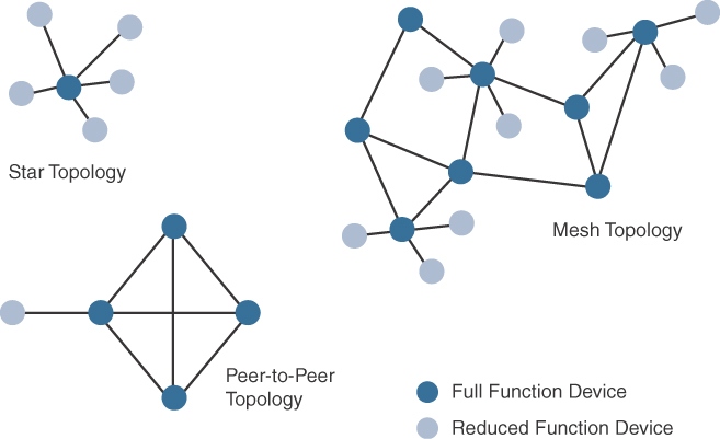
For example, indoor Wi-Fi deployments are mostly a set of nodes forming a star topology around their access points (APs). Meanwhile, outdoor Wi-Fi may consist of a mesh topology for the backbone of APs, with nodes connecting to the APs in a star topology. Similarly, IEEE 802.15.4 and 802.15.4g and even wired IEEE 1901.2a PLC are generally deployed as a mesh topology. A mesh topology helps cope with low transmit power, searching to reach a greater overall distance, and coverage by having intermediate nodes relaying traffic for other nodes.
Mesh topology requires the implementation of a Layer 2 forwarding protocol known as mesh-under or a Layer 3 forwarding protocol referred to as mesh-over on each intermediate node. (See Chapter 5, “IP as the IoT Network Layer,” for more information.) As discussed previously in Chapter 2, “IoT Network Architecture and Design,” an intermediate node or full-function device (FFD) is simply a node that interconnects other nodes. A node that doesn’t interconnect or relay the traffic of other nodes is known as a leaf node, or reduced-function device (RFD). (More information on full-function and reduced-function devices is also presented later in this chapter.)
While well adapted to powered nodes, mesh topology requires a properly optimized implementation for battery-powered nodes. Battery-powered nodes are often placed in a “sleep mode” to preserve battery life when not transmitting. In the case of mesh topology, either the battery-powered nodes act as leaf nodes or as a “last resource path” to relay traffic when used as intermediate nodes. Otherwise, battery lifetime is greatly shortened. For battery-powered nodes, the topology type and the role of the node in the topology (for example, being an intermediate or leaf node) are significant factors for a successful implementation.
Constrained Devices
The Internet Engineering Task Force (IETF) acknowledges in RFC 7228 that different categories of IoT devices are deployed. While categorizing the class of IoT nodes is a perilous exercise, with computing, memory, storage, power, and networking continuously evolving and improving, RFC 7228 gives some definitions of constrained nodes. These definitions help differentiate constrained nodes from unconstrained nodes, such as servers, desktop or laptop computers, and powerful mobile devices such as smart phones.
Constrained nodes have limited resources that impact their networking feature set and capabilities. Therefore, some classes of IoT nodes do not implement an IP stack. According to RFC 7228, constrained nodes can be broken down into the classes defined in Table 4-1.

Constrained-Node Networks
While several of the IoT access technologies, such as Wi-Fi and cellular, are applicable to laptops, smart phones, and some IoT devices, some IoT access technologies are more suited to specifically connect constrained nodes. Typical examples are IEEE 802.15.4 and 802.15.4g RF, IEEE 1901.2a PLC, LPWA, and IEEE 802.11ah access technologies. (These technologies are discussed in more detail later in this chapter.)
Constrained-node networks are often referred to as low-power and lossy networks (LLNs). (See Chapter 5 for more details on LLNs.) Low-power in the context of LLNs refers to the fact that nodes must cope with the requirements from powered and battery-powered constrained nodes. Lossy networks indicates that network performance may suffer from interference and variability due to harsh radio environments. Layer 1 and Layer 2 protocols that can be used for constrained-node networks must be evaluated in the context of the following characteristics for use-case applicability: data rate and throughput, latency and determinism, and overhead and payload.
Data Rate and Throughput
The data rates available from IoT access technologies range from 100 bps with protocols such as Sigfox to tens of megabits per second with technologies such as LTE and IEEE 802.11ac. (Sigfox, LTE, and IEEE 802.11ac are discussed later in this chapter.) However, the actual throughput is less—sometimes much less—than the data rate. Therefore, understanding the bandwidth requirements of a particular technology, its applicability to given use cases, the capacity planning rules, and the expected real throughput are important for proper network design and successful production deployment.
Technologies not particularly designed for IoT, such as cellular and Wi-Fi, match up well to IoT applications with high bandwidth requirements. For example, nodes involved with video analytics have a need for high data rates. These nodes are found in retail, airport, and smart cities environments for detecting events and driving actions. Because these types of IoT endpoints are not constrained in terms of computing or network bandwidth, the design guidelines tend to focus on application requirements, such as latency and determinism. (Latency and determinism is discussed in more detail later in this chapter.)
Short-range technologies can also provide medium to high data rates that have enough throughput to connect a few endpoints. For example, Bluetooth sensors that are now appearing on connected wearables fall into this category. In this case, the solutions focus more on footprint and battery lifetime than on data rate.
The IoT access technologies developed for constrained nodes are optimized for low power consumption, but they are also limited in terms of data rate, which depends on the selected frequency band, and throughput.
With the data rate ranging from 100 bps to less than 1 Mbps, you may think back to the years when bandwidth was a scarce resource. You often needed some expertise to understand how to design such networks. Today this sort of expertise is helpful for LPWA networks, which are designed with a certain number of messages per day or per endpoint rather than just having a pure bandwidth usage limit in place. In addition, in an access mesh topology, an application’s behavior, such as frequency polling, impacts the design because all devices share the constrained bandwidth capacity.
A discussion of data rate and bandwidth in LLNs must include a look at real throughput, or “goodput,” as seen by the application. While it may not be important for constrained nodes that send only one message a day, real throughput is often very important for constrained devices implementing an IP stack. In this case, throughput is a lower percentage of the data rate, even if the node gets the full constrained network at a given time.
For example, let’s consider an IEEE 802.15.4g subnetwork implementing 2FSK modulation at 150 kbps for the 915 MHz frequency band. (The IEEE 802.15.4g protocol is covered in more detail later in this chapter.) To cover the border case of distance and radio signal quality, Forward Error Correction (FEC) will be turned on, which lowers the data rate from 150 kbps to 75 kbps. If you now add in the protocol stack overhead, the two-way communication handling, and the variable data payload size, you end up with a maximum throughput of 30 to 40 kbps. This must be considered as the best value because the number of devices simultaneously communicating along with the topology and control plane overhead will also impact the throughput.
Another characteristic of IoT devices is that a majority of them initiate the communication. Upstream traffic toward an application server is usually more common than downstream traffic from the application server. Understanding this behavior also helps when deploying an IoT access technology, such as cellular, that is asymmetrical because the upstream bandwidth must be considered a key parameter for profiling the network capacity.
Latency and Determinism
Much like throughput requirements, latency expectations of IoT applications should be known when selecting an access technology. This is particularly true for wireless networks, where packet loss and retransmissions due to interference, collisions, and noise are normal behaviors.
On constrained networks, latency may range from a few milliseconds to seconds, and applications and protocol stacks must cope with these wide-ranging values. For example, UDP at the transport layer is strongly recommended for IP endpoints communicating over LLNs. In the case of mesh topologies, if communications are needed between two devices inside the mesh, the forwarding path may call for some routing optimization, which is available using the IPv6 RPL protocol. (For more information on RPL, see Chapter 5.)
Note
When latency is a strong concern, emergent access technologies such as Deterministic Ethernet or the Time-Slotted Channel Hopping (TSCH) mode of IEEE 802.15.4e should be considered. However, some of these solutions are not fully mature for production deployment. (For more information on TSCH, see Chapter 5. The 802.15.4e protocol is discussed later in this chapter.)
Overhead and Payload
When considering constrained access network technologies, it is important to review the MAC payload size characteristics required by applications. In addition, you should be aware of any requirements for IP. The minimum IPv6 MTU size is expected to be 1280 bytes. Therefore, the fragmentation of the IPv6 payload has to be taken into account by link layer access protocols with smaller MTUs.
Note
The use of IP on IoT devices is an open topic of discussion. As mentioned earlier in this chapter, the IETF acknowledges the fact that different classes of IoT devices exist. For the more constrained classes of devices, like Class 0 and Class 1 devices, it is usually not possible or optimal to implement a complete IP stack implementation.
For technologies that fall under the LLN definition but are able to transport IP, such as IEEE 802.15.4 and 802.15.4g, IEEE 1901.2, and IEEE 802.11ah, Layer 1 or Layer 2 fragmentation capabilities and/or IP optimization is important. (The protocols IEEE 802.14 and 802.15.4g, IEEE 1901.2, and IEEE 802.11ah are covered later in this chapter.) For example, the payload size for IEEE 802.15.4 is 127 bytes and requires an IPv6 payload with a minimum MTU of 1280 bytes to be fragmented. (For more information on the fragmentation of IPv6, see Chapter 5.) On the other hand, IEEE 802.15.4g enables payloads up to 2048 bytes, easing the support of the IPv6 minimum MTU of 1280 bytes.
Most LPWA technologies offer small payload sizes. These small payload sizes are defined to cope with the low data rate and time over the air or duty cycle requirements of IoT nodes and sensors. For example, payloads may be as little as 19 bytes using LoRaWAN technology or up to 250 bytes, depending on the adaptive data rate (ADR). While this doesn’t preclude the use of an IPv6/6LoWPAN payload, as seen on some endpoint implementations, these types of protocols are better suited to Class 0 and 1 nodes, as defined in RFC 7228. (LoRaWAN and ADR are discussed in more detail later in this chapter. RFC 7228 and the node classes it defines are covered earlier in this chapter.)
In conclusion, the communication criteria just covered are fundamental to understanding IoT access technologies, their characteristics, and when they are most applicable. These criteria include range, frequency bands, power consumption, network topology, the presence of constrained devices and/or networks, and data throughput.
From a network engineer perspective, you must make sure an architecture is developed with the proper abstraction for a particular access technology. This is especially true for constrained network nodes, where quite often your choices of protocols and solutions can be limited. The next section reviews the main IoT access technologies dedicated to constrained networks.
IoT Access Technologies
The previous section describes criteria that help you in evaluating IoT constrained network technologies for proper design and operations. This section provides an overview of the main IoT access technologies. The technologies highlighted here are the ones that are seen as having market and/or mind share. Therefore, you should have a basic familiarity with them as they are fundamental to many IoT conversations.
Note
Remember that there are many more IoT technologies in the market today than we can discuss here. This chapter focuses on the ones that appear to have the strongest foothold.
For each of the IoT access technologies discussed in this chapter, a common information set is being provided. Particularly, the following topics are addressed for each IoT access technology:
![]() Standardization and alliances: The standards bodies that maintain the protocols for a technology
Standardization and alliances: The standards bodies that maintain the protocols for a technology
![]() Physical layer: The wired or wireless methods and relevant frequencies
Physical layer: The wired or wireless methods and relevant frequencies
![]() MAC layer: Considerations at the Media Access Control (MAC) layer, which bridges the physical layer with data link control
MAC layer: Considerations at the Media Access Control (MAC) layer, which bridges the physical layer with data link control
![]() Topology: The topologies supported by the technology
Topology: The topologies supported by the technology
![]() Security: Security aspects of the technology
Security: Security aspects of the technology
![]() Competitive technologies: Other technologies that are similar and may be suitable alternatives to the given technology
Competitive technologies: Other technologies that are similar and may be suitable alternatives to the given technology
While having a familiarity with these protocols and their capabilities is recommended, you may find that much of the information about these technologies is better used as reference material. When you encounter these protocols, you can use this chapter as a handy overview and quick summary of the important details.
IEEE 802.15.4
IEEE 802.15.4 is a wireless access technology for low-cost and low-data-rate devices that are powered or run on batteries. In addition to being low cost and offering a reasonable battery life, this access technology enables easy installation using a compact protocol stack while remaining both simple and flexible. Several network communication stacks, including deterministic ones, and profiles leverage this technology to address a wide range of IoT use cases in both the consumer and business markets. IEEE 802.15.4 is commonly found in the following types of deployments:
![]() Home and building automation
Home and building automation
![]() Automotive networks
Automotive networks
![]() Industrial wireless sensor networks
Industrial wireless sensor networks
![]() Interactive toys and remote controls
Interactive toys and remote controls
Criticisms of IEEE 802.15.4 often focus on its MAC reliability, unbounded latency, and susceptibility to interference and multipath fading. The negatives around reliability and latency often have to do with the Collision Sense Multiple Access/Collision Avoidance (CSMA/CA) algorithm. CSMA/CA is an access method in which a device “listens” to make sure no other devices are transmitting before starting its own transmission. If another device is transmitting, a wait time (which is usually random) occurs before “listening” occurs again. Interference and multipath fading occur with IEEE 802.15.4 because it lacks a frequency-hopping technique. Later variants of 802.15.4 from the IEEE start to address these issues. (See the section “IEEE 802.15.4e and 802.15.4g,” later in this chapter, for more information.)
Note
Most forms of radio communications are affected by multipath fading to varying degrees. Multipath fading refers to multiple copies of the signal hitting the receiver at different points in time because of different signal paths and reflections. The ability to change frequencies can mitigate the effects of multipath fading.
Standardization and Alliances
IEEE 802.15.4 or IEEE 802.15 Task Group 4 defines low-data-rate PHY and MAC layer specifications for wireless personal area networks (WPAN). This standard has evolved over the years and is a well-known solution for low-complexity wireless devices with low data rates that need many months or even years of battery life. For more detailed information on IEEE 802.15.4, visit www.ieee802.org/15/pub/TG4.html.
Since 2003, the IEEE has published several iterations of the IEEE 802.15.4 specification, each labeled with the publication’s year. For example, IEEE 802.15.4-2003 was published in 2003, 802.15.4-2006 was released in 2006, and 802.15.4-2011 and 802.15.4-2015 were issued in 2011 and 2015, respectively. Newer releases typically supersede older ones, integrate addendums, and add features or clarifications to previous versions.
While there is no alliance or promotion body for IEEE 802.15.4 per se, the IEEE 802.15.4 PHY and MAC layers are the foundations for several networking protocol stacks. These protocol stacks make use of 802.15.4 at the physical and link layer levels, but the upper layers are different. These protocol stacks are promoted separately through various organizations and often commercialized. Some of the most well-known protocol stacks based on 802.15.4 are highlighted in Table 4-2.


Because of its relatively long history compared to the others, ZigBee is one of the most well-known protocols listed in Table 4-2. In addition, ZigBee has continued to evolve over time as evidenced by the release of Zigbee IP and is representative of how IEEE 802.15.4 can be leveraged at the PHY and MAC layers, independent of the protocol layers above. For these reasons, both Zigbee and Zigbee IP are discussed in more detail in the following sections.
ZigBee
Based on the idea of ZigBee-style networks in the late 1990s, the first ZigBee specification was ratified in 2004, shortly after the release of the IEEE 802.15.4 specification the previous year. While not released as a typical standard, like an RFC, ZigBee still had industry support from more than 100 companies upon its initial publication. This industry support has grown to more than 400 companies that are members of the ZigBee Alliance. Similar to the Wi-Fi Alliance, the Zigbee Alliance is an industry group formed to certify interoperability between vendors and it is committed to driving and evolving ZigBee as an IoT solution for interconnecting smart objects.
ZigBee solutions are aimed at smart objects and sensors that have low bandwidth and low power needs. Furthermore, products that are ZigBee compliant and certified by the ZigBee Alliance should interoperate even though different vendors may manufacture them.
The Zigbee specification has undergone several revisions. In the 2006 revision, sets of commands and message types were introduced, and increased in number in the 2007 (called Zigbee pro) iteration, to achieve different functions for a device, such as metering, temperature, or lighting control. These sets of commands and message types are called clusters. Ultimately, these clusters from different functional domains or libraries form the building blocks of Zigbee application profiles. Vendors implementing pre-defined Zigbee application profiles like Home Automation or Smart Energy can ensure interoperability between their products.
The main areas where ZigBee is the most well-known include automation for commercial, retail, and home applications and smart energy. In the industrial and commercial automation space, ZigBee-based devices can handle various functions, from measuring temperature and humidity to tracking assets. For home automation, ZigBee can control lighting, thermostats, and security functions. ZigBee Smart Energy brings together a variety of interoperable products, such as smart meters, that can monitor and control the use and delivery of utilities, such as electricity and water. These ZigBee products are controlled by the utility provider and can help coordinate usage between homes and businesses and the utility provider itself to provide more efficient operations.
The traditional ZigBee stack is illustrated in Figure 4-3. As mentioned previously, ZigBee utilizes the IEEE 802.15.4 standard at the lower PHY and MAC layers. (The 802.15.4 PHY and MAC layers are covered in detail later in this chapter.) ZigBee specifies the network and security layer and application support layer that sit on top of the lower layers.
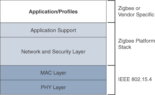
The ZigBee network and security layer provides mechanisms for network startup, configuration, routing, and securing communications. This includes calculating routing paths in what is often a changing topology, discovering neighbors, and managing the routing tables as devices join for the first time. The network layer is also responsible for forming the appropriate topology, which is often a mesh but could be a star or tree as well. From a security perspective, ZigBee utilizes 802.15.4 for security at the MAC layer, using the Advanced Encryption Standard (AES) with a 128-bit key and also provides security at the network and application layers.
Note
ZigBee uses Ad hoc On-Demand Distance Vector (AODV) routing across a mesh network. Interestingly, this routing algorithm does not send a message until a route is needed. Assuming that the next hop for a route is not in its routing table, a network node broadcasts a request for a routing connection. This causes a burst of routing-related traffic, but after a comparison of various responses, the path with the lowest number of hops is determined for the connection. This process is quite different from standard enterprise routing protocols, which usually learn the entire network topology in some manner and then store a consolidated but complete routing table.
The application support layer in Figure 4-3 interfaces the lower portion of the stack dealing with the networking of ZigBee devices with the higher-layer applications. ZigBee predefines many application profiles for certain industries, and vendors can optionally create their own custom ones at this layer. As mentioned previously, Home Automation and Smart Energy are two examples of popular application profiles.
ZigBee is one of the most well-known protocols built on an IEEE 802.15.4 foundation. On top of the 802.15.4 PHY and MAC layers, ZigBee specifies its own network and security layer and application profiles. While this structure has provided a fair degree of interoperability for vendors with membership in the ZigBee Alliance, it has not provided interoperability with other IoT solutions. However, this has started to change with the release of ZigBee IP, which is discussed next.
ZigBee IP
With the introduction of ZigBee IP, the support of IEEE 802.15.4 continues, but the IP and TCP/UDP protocols and various other open standards are now supported at the network and transport layers. The ZigBee-specific layers are now found only at the top of the protocol stack for the applications.
ZigBee IP was created to embrace the open standards coming from the IETF’s work on LLNs, such as IPv6, 6LoWPAN, and RPL. (These IETF standards are discussed in Chapter 5.) They provide for low-bandwidth, low-power, and cost-effective communications when connecting smart objects.
ZigBee IP is a critical part of the Smart Energy (SE) Profile 2.0 specification from the ZigBee Alliance. SE 2.0 is aimed at smart metering and residential energy management systems. In fact, ZigBee IP was designed specifically for SE 2.0 but it is not limited to this use case. Any other applications that need a standards-based IoT stack can utilize Zigbee IP. The ZigBee IP stack is shown in Figure 4-4.

Unlike traditional ZigBee, discussed in the previous section, ZigBee IP supports 6LoWPAN as an adaptation layer. (The 6LoWPAN protocol is covered in Chapter 5.) The 6LoWPAN mesh addressing header is not required as ZigBee IP utilizes the mesh-over or route-over method for forwarding packets. ZigBee IP requires the support of 6LoWPAN’s fragmentation and header compression schemes.
At the network layer, all ZigBee IP nodes support IPv6, ICMPv6, and 6LoWPAN Neighbor Discovery (ND), and utilize RPL for the routing of packets across the mesh network. IPv6 and RPL are discussed in more detail in Chapter 5. Both TCP and UDP are also supported, to provide both connection-oriented and connectionless service.
As you can see, ZigBee IP is a compelling protocol stack offering because it is based on current IoT standards at every layer under the application layer. This opens up opportunities for ZigBee IP to integrate and interoperate on just about any 802.15.4 network with other solutions built on these open IoT standards. The following sections take a deeper dive into 802.15.4 and its PHY and MAC layers.
Physical Layer
The 802.15.4 standard supports an extensive number of PHY options that range from 2.4 GHz to sub-GHz frequencies in ISM bands. (ISM bands are discussed earlier in this chapter.) The original IEEE 802.15.4-2003 standard specified only three PHY options based on direct sequence spread spectrum (DSSS) modulation. DSSS is a modulation technique in which a signal is intentionally spread in the frequency domain, resulting in greater bandwidth. The original physical layer transmission options were as follows:
![]() 2.4 GHz, 16 channels, with a data rate of 250 kbps
2.4 GHz, 16 channels, with a data rate of 250 kbps
![]() 915 MHz, 10 channels, with a data rate of 40 kbps
915 MHz, 10 channels, with a data rate of 40 kbps
![]() 868 MHz, 1 channel, with a data rate of 20 kbps
868 MHz, 1 channel, with a data rate of 20 kbps
You should note that only the 2.4 GHz band operates worldwide. The 915 MHz band operates mainly in North and South America, and the 868 MHz frequencies are used in Europe, the Middle East, and Africa. IEEE 802.15.4-2006, 802.15.4-2011, and IEEE 802.15.4-2015 introduced additional PHY communication options, including the following:
![]() OQPSK PHY: This is DSSS PHY, employing offset quadrature phase-shift keying (OQPSK) modulation. OQPSK is a modulation technique that uses four unique bit values that are signaled by phase changes. An offset function that is present during phase shifts allows data to be transmitted more reliably.
OQPSK PHY: This is DSSS PHY, employing offset quadrature phase-shift keying (OQPSK) modulation. OQPSK is a modulation technique that uses four unique bit values that are signaled by phase changes. An offset function that is present during phase shifts allows data to be transmitted more reliably.
![]() BPSK PHY: This is DSSS PHY, employing binary phase-shift keying (BPSK) modulation. BPSK specifies two unique phase shifts as its data encoding scheme.
BPSK PHY: This is DSSS PHY, employing binary phase-shift keying (BPSK) modulation. BPSK specifies two unique phase shifts as its data encoding scheme.
![]() ASK PHY: This is parallel sequence spread spectrum (PSSS) PHY, employing amplitude shift keying (ASK) and BPSK modulation. PSSS is an advanced encoding scheme that offers increased range, throughput, data rates, and signal integrity compared to DSSS. ASK uses amplitude shifts instead of phase shifts to signal different bit values.
ASK PHY: This is parallel sequence spread spectrum (PSSS) PHY, employing amplitude shift keying (ASK) and BPSK modulation. PSSS is an advanced encoding scheme that offers increased range, throughput, data rates, and signal integrity compared to DSSS. ASK uses amplitude shifts instead of phase shifts to signal different bit values.
These improvements increase the maximum data rate for both 868 MHz and 915 MHz to 100 kbps and 250 kbps, respectively. The 868 MHz support was enhanced to 3 channels, while other IEEE 802.15.4 study groups produced addendums for new frequency bands. For example, the IEEE 802.15.4c study group created the bands 314–316 MHz, 430–434 MHz, and 779–787 MHz for use in China.
Figure 4-5 shows the frame for the 802.15.4 physical layer. The synchronization header for this frame is composed of the Preamble and the Start of Frame Delimiter fields. The Preamble field is a 32-bit 4-byte (for parallel construction) pattern that identifies the start of the frame and is used to synchronize the data transmission. The Start of Frame Delimiter field informs the receiver that frame contents start immediately after this byte.
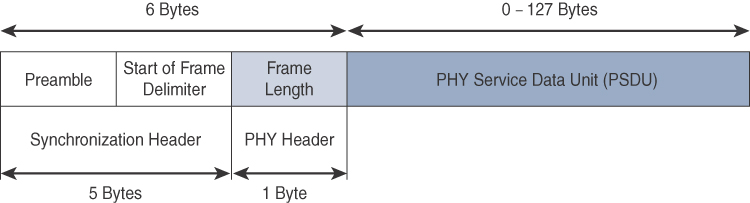
The PHY Header portion of the PHY frame shown in Figure 4-5 is simply a frame length value. It lets the receiver know how much total data to expect in the PHY service data unit (PSDU) portion of the 802.4.15 PHY. The PSDU is the data field or payload.
Note
The maximum size of the IEEE 802.15.4 PSDU is 127 bytes. This size is significantly smaller than the lowest MTU setting of other upper-layer protocols, such as IPv6, which has a minimum MTU setting of 1280 bytes. Therefore, fragmentation of the IPv6 packet must occur at the data link layer for larger IPv6 packets to be carried over IEEE 802.15.4 frames. (See Chapter 5 for more details.)
The various versions and addendums to 802.15.4 over the years through various working groups can make it somewhat difficult to follow. Therefore, you should pay attention to which versions of 802.15.4 particular devices support. Products and solutions must refer to the proper IEEE 802.15.4 specification, frequency band, modulation, and data rate when providing details on their physical layer implementation.
MAC Layer
The IEEE 802.15.4 MAC layer manages access to the PHY channel by defining how devices in the same area will share the frequencies allocated. At this layer, the scheduling and routing of data frames are also coordinated. The 802.15.4 MAC layer performs the following tasks:
![]() Network beaconing for devices acting as coordinators (New devices use beacons to join an 802.15.4 network)
Network beaconing for devices acting as coordinators (New devices use beacons to join an 802.15.4 network)
![]() PAN association and disassociation by a device
PAN association and disassociation by a device
![]() Device security
Device security
![]() Reliable link communications between two peer MAC entities
Reliable link communications between two peer MAC entities
The MAC layer achieves these tasks by using various predefined frame types. In fact, four types of MAC frames are specified in 802.15.4:
![]() Data frame: Handles all transfers of data
Data frame: Handles all transfers of data
![]() Beacon frame: Used in the transmission of beacons from a PAN coordinator
Beacon frame: Used in the transmission of beacons from a PAN coordinator
![]() Acknowledgement frame: Confirms the successful reception of a frame
Acknowledgement frame: Confirms the successful reception of a frame
![]() MAC command frame: Responsible for control communication between devices
MAC command frame: Responsible for control communication between devices
Each of these four 802.15.4 MAC frame types follows the frame format shown in Figure 4-6. In Figure 4-6, notice that the MAC frame is carried as the PHY payload. The 802.15.4 MAC frame can be broken down into the MAC Header, MAC Payload, and MAC Footer fields.

The MAC Header field is composed of the Frame Control, Sequence Number and the Addressing fields. The Frame Control field defines attributes such as frame type, addressing modes, and other control flags. The Sequence Number field indicates the sequence identifier for the frame. The Addressing field specifies the Source and Destination PAN Identifier fields as well as the Source and Destination Address fields.
Note
Within the Frame Control portion of the 802.15.4 header is the Security Enabled field. When this field is set to a value of 0, the frame format matches Figure 4-6. Beginning with the 802.15.4-2006 specification, when this field is set to a value of 1, an Auxiliary Security Header field is added to the 802.15.4 frame, as shown later, in Figure 4-8.
The MAC Payload field varies by individual frame type. For example, beacon frames have specific fields and payloads related to beacons, while MAC command frames have different fields present. The MAC Footer field is nothing more than a frame check sequence (FCS). An FCS is a calculation based on the data in the frame that is used by the receiving side to confirm the integrity of the data in the frame.
IEEE 802.15.4 requires all devices to support a unique 64-bit extended MAC address, based on EUI-64. However, because the maximum payload is 127 bytes, 802.15.4 also defines how a 16-bit “short address” is assigned to devices. This short address is local to the PAN and substantially reduces the frame overhead compared to a 64-bit extended MAC address. However, you should be aware that the use of this short address might be limited to specific upper-layer protocol stacks.
Topology
IEEE 802.15.4–based networks can be built as star, peer-to-peer, or mesh topologies. Mesh networks tie together many nodes. This allows nodes that would be out of range if trying to communicate directly to leverage intermediary nodes to transfer communications.
Please note that every 802.15.4 PAN should be set up with a unique ID. All the nodes in the same 802.15.4 network should use the same PAN ID. Figure 4-7 shows an example of an 802.15.4 mesh network with a PAN ID of 1.
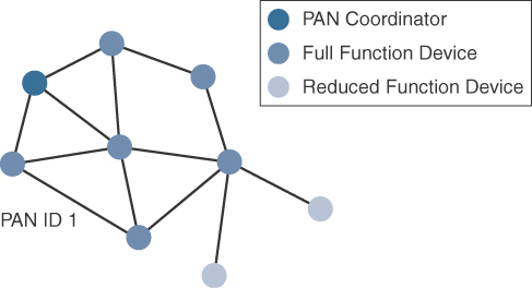
As mentioned earlier in this chapter, full-function devices (FFDs) and reduced-function devices (RFDs) are defined in IEEE 802.15.4. A minimum of one FFD acting as a PAN coordinator is required to deliver services that allow other devices to associate and form a cell or PAN. Notice in Figure 4-7 that a single PAN coordinator is identified for PAN ID 1. FFD devices can communicate with any other devices, whereas RFD devices can communicate only with FFD devices.
The IEEE 802.15.4 specification does not define a path selection within the MAC layer for a mesh topology. This function can be done at Layer 2 and is known as mesh-under. Generally, this is based on a proprietary solution. Alternatively, the routing function can occur at Layer 3, using a routing protocol, such as the IPv6 Routing Protocol for Low Power and Lossy Networks (RPL). This is referred to as mesh-over. (To learn more about mesh-under, mesh-over, and RPL, see Chapter 5.)
Security
The IEEE 802.15.4 specification uses Advanced Encryption Standard (AES) with a 128-bit key length as the base encryption algorithm for securing its data. Established by the US National Institute of Standards and Technology in 2001, AES is a block cipher, which means it operates on fixed-size blocks of data. The use of AES by the US government and its widespread adoption in the private sector has helped it become one of the most popular algorithms used in symmetric key cryptography. (A symmetric key means that the same key is used for both the encryption and decryption of the data.)
In addition to encrypting the data, AES in 802.15.4 also validates the data that is sent. This is accomplished by a message integrity code (MIC), which is calculated for the entire frame using the same AES key that is used for encryption.
Enabling these security features for 802.15.4 changes the frame format slightly and consumes some of the payload. Using the Security Enabled field in the Frame Control portion of the 802.15.4 header is the first step to enabling AES encryption. This field is a single bit that is set to 1 for security. Once this bit is set, a field called the Auxiliary Security Header is created after the Source Address field, by stealing some bytes from the Payload field. Figure 4-8 shows the IEEE 802.15.4 frame format at a high level, with the Security Enabled bit set and the Auxiliary Security Header field present.
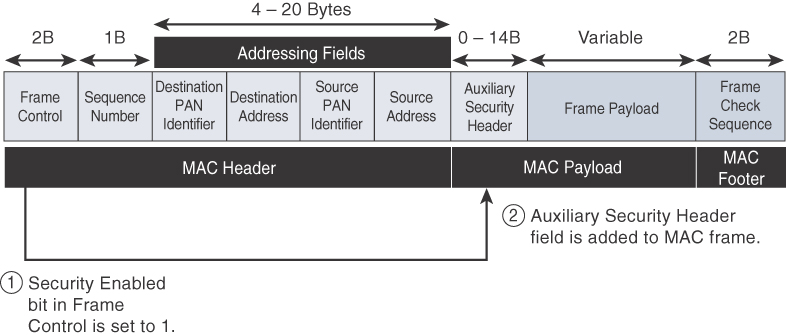
Figure 4-8 Frame Format with the Auxiliary Security Header Field for 802.15.4-2006 and Later Versions
Competitive Technologies
As detailed in Table 4-2, the IEEE 802.15.4 PHY and MAC layers are the foundations for several networking profiles that compete against each other in various IoT access environments. These various vendors and organizations build upper-layer protocol stacks on top of an 802.15.4 core. They compete and distinguish themselves based on features and capabilities in these upper layers.
A competitive radio technology that is different in its PHY and MAC layers is DASH7. DASH7 was originally based on the ISO18000-7 standard and positioned for industrial communications, whereas IEEE 802.15.4 is more generic. Commonly employed in active radio frequency identification (RFID) implementations, DASH7 was used by US military forces for many years, mainly for logistics purposes. Active RFID utilizes radio waves generated by a battery-powered tag on an object to enable continuous tracking.
The current DASH7 technology offers low power consumption, a compact protocol stack, range up to 1 mile, and AES encryption. Frequencies of 433 MHz, 868 MHz, and 915 MHz have been defined, enabling data rates up to 166.667 kbps and a maximum payload of 256 bytes.
DASH7 is promoted by the DASH7 Alliance, which has evolved the protocol from its active RFID niche into a wireless sensor network technology that is aimed at the commercial market. For more information on DASH7, see the Dash7 Alliance webpage, at www.dash7-alliance.org.
IEEE 802.15.4 Conclusions
The IEEE 802.15.4 wireless PHY and MAC layers are mature specifications that are the foundation for various industry standards and products (refer to Table 4-2). The PHY layer offers a maximum speed of up to 250 kbps, but this varies based on modulation and frequency. The MAC layer for 802.15.4 is robust and handles how data is transmitted and received over the PHY layer. Specifically, the MAC layer handles the association and disassociation of devices to/from a PAN, reliable communications between devices, security, and the formation of various topologies.
The topologies used in 802.15.4 include star, peer-to-peer, and cluster trees that allow for the formation of mesh networks. From a security perspective, 802.15.4 utilizes AES encryption to allow secure communications and also provide data integrity.
The main competitor to IEEE 802.15.4 is DASH7, another wireless technology that compares favorably. However, IEEE 802.15.4 has an edge in the marketplace through all the different vendors and organizations that utilize its PHY and MAC layers. As 802.15.4 continues to evolve, you will likely see broader adoption of the IPv6 standard at the network layer. For IoT sensor deployments requiring low power, low data rate, and low complexity, the IEEE 802.15.4 standard deserves strong consideration.
IEEE 802.15.4g and 802.15.4e
The IEEE frequently makes amendments to the core 802.15.4 specification, before integrating them into the next revision of the core specification. When these amendments are made, a lowercase letter is appended. Two such examples of this are 802.15.4e-2012 and 802.15.4g-2012, both of which are especially relevant to the subject of IoT. Both of these amendments were integrated in IEEE 802.15.4-2015 but are often still referred to by their amendment names.
The IEEE 802.15.4e amendment of 802.15.4-2011 expands the MAC layer feature set to remedy the disadvantages associated with 802.15.4, including MAC reliability, unbounded latency, and multipath fading. In addition to making general enhancements to the MAC layer, IEEE 802.15.4e also made improvements to better cope with certain application domains, such as factory and process automation and smart grid. Smart grid is associated with the modernization of the power grid and utilities infrastructure by connecting intelligent devices and communications. IEEE 802.15.4e-2012 enhanced the IEEE 802.15.4 MAC layer capabilities in the areas of frame format, security, determinism mechanism, and frequency hopping. (The specific MAC layer enhancements introduced in IEEE 802.15.4e are covered in more detail later in this chapter.)
IEEE 802.15.4g-2012 is also an amendment to the IEEE 802.15.4-2011 standard, and just like 802.15.4e-2012, it has been fully integrated into the core IEEE 802.15.4-2015 specification. The focus of this specification is the smart grid or, more specifically, smart utility network communication. 802.15.4g seeks to optimize large outdoor wireless mesh networks for field area networks (FANs). New PHY definitions are introduced, as well as some MAC modifications needed to support their implementation. This technology applies to IoT use cases such as the following:
![]() Distribution automation and industrial supervisory control and data acquisition (SCADA) environments for remote monitoring and control (SCADA is covered in more detail in Chapter 6, “Application Protocols for IoT.”)
Distribution automation and industrial supervisory control and data acquisition (SCADA) environments for remote monitoring and control (SCADA is covered in more detail in Chapter 6, “Application Protocols for IoT.”)
![]() Public lighting
Public lighting
![]() Environmental wireless sensors in smart cities
Environmental wireless sensors in smart cities
![]() Electrical vehicle charging stations
Electrical vehicle charging stations
![]() Smart parking meters
Smart parking meters
![]() Microgrids
Microgrids
![]() Renewable energy
Renewable energy
Note
The IEEE continues to improve the 802.15.4 specification through amendments. For example, IEEE 802.15.4u defines the PHY layer characteristics for India (865–867 MHz). Meanwhile, IEEE 802.15.4v defines changes to the SUN PHYs, enabling the use of the 870–876 MHz and 915–921 MHz bands in Europe, the 902–928 MHz band in Mexico, the 902–907.5 MHz and 915–928 MHz bands in Brazil, the 915–928 MHz band in Australia/New Zealand, and Asian regional frequency bands that are not in IEEE 802.15.4-2015.
Standardization and Alliances
Because 802.15.4g-2012 and 802.15.4e-2012 are simply amendments to IEEE 802.15.4-2011, the same IEEE 802.15 Task Group 4 standards body authors, maintains, and integrates them into the next release of the core specification. However, the additional capabilities and options provided by 802.15.4g-2012 and 802.15.4e-2012 led to additional difficulty in achieving the interoperability between devices and mixed vendors that users requested.
To guarantee interoperability, the Wi-SUN Alliance was formed. (SUN stands for smart utility network.) This organization is not a standards body but is instead an industry alliance that defines communication profiles for smart utility and related networks. These profiles are based on open standards, such as 802.15.4g-2012, 802.15.4e-2012, IPv6, 6LoWPAN, and UDP for the FAN profile. (For more information on 6LoWPAN, see Chapter 5.) In addition, Wi-SUN offers a testing and certification program to further ensure interoperability.
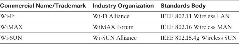
The Wi-SUN Alliance performs the same function as the Wi-Fi Alliance and WiMAX Forum. Each of these organizations has an associated standards body as well as a commercial name, as shown in Table 4-3. For more information on Wi-SUN, visit www.wi-sun.org.
Physical Layer
In IEEE 802.15.4g-2012, the original IEEE 802.15.4 maximum PSDU or payload size of 127 bytes was increased for the SUN PHY to 2047 bytes. This provides a better match for the greater packet sizes found in many upper-layer protocols. For example, the default IPv6 MTU setting is 1280 bytes. Fragmentation is no longer necessary at Layer 2 when IPv6 packets are transmitted over IEEE 802.15.4g MAC frames. Also, the error protection was improved in IEEE 802.15.4g by evolving the CRC from 16 to 32 bits.
The SUN PHY, as described in IEEE 802.15.4g-2012, supports multiple data rates in bands ranging from 169 MHz to 2.4 GHz. These bands are covered in the unlicensed ISM frequency spectrum specified by various countries and regions. Within these bands, data must be modulated onto the frequency using at least one of the following PHY mechanisms to be IEEE 802.15.4g compliant:
![]() Multi-Rate and Multi-Regional Frequency Shift Keying (MR-FSK): Offers good transmit power efficiency due to the constant envelope of the transmit signal
Multi-Rate and Multi-Regional Frequency Shift Keying (MR-FSK): Offers good transmit power efficiency due to the constant envelope of the transmit signal
![]() Multi-Rate and Multi-Regional Orthogonal Frequency Division Multiplexing (MR-OFDM): Provides higher data rates but may be too complex for low-cost and low-power devices
Multi-Rate and Multi-Regional Orthogonal Frequency Division Multiplexing (MR-OFDM): Provides higher data rates but may be too complex for low-cost and low-power devices
![]() Multi-Rate and Multi-Regional Offset Quadrature Phase-Shift Keying (MR-O-QPSK): Shares the same characteristics of the IEEE 802.15.4-2006 O-QPSK PHY, making multi-mode systems more cost-effective and easier to design
Multi-Rate and Multi-Regional Offset Quadrature Phase-Shift Keying (MR-O-QPSK): Shares the same characteristics of the IEEE 802.15.4-2006 O-QPSK PHY, making multi-mode systems more cost-effective and easier to design
Enhanced data rates and a greater number of channels for channel hopping are available, depending on the frequency bands and modulation. For example, for the 902–928 MHz ISM band that is used in the United States, MR-FSK provides 50, 150, or 200 kbps. MR-OFDM at this same frequency allows up to 800 kbps. Other frequencies provide their own settings.
Therefore, products and solutions must refer to the proper IEEE 802.15.4 specification, frequency band, modulation, and data rate when providing details about their PHY implementation. This is important because the availability of chipsets supporting new PHY mechanisms, such as MR-OFDM, may limit the implementation of enhanced data rates. You should look to the Wi-SUN Alliance to mitigate these problems and provide some consistency in terms of implementation, interoperability, and certifications. For example, the Wi-SUN PHY working group publishes a Regional Frequency Bands specification describing the details for various regions and countries.
MAC Layer
While the IEEE 802.15.4e-2012 amendment is not applicable to the PHY layer, it is pertinent to the MAC layer. This amendment enhances the MAC layer through various functions, which may be selectively enabled based on various implementations of the standard. In fact, if interoperability is a “must have,” then using profiles defined by organizations such as Wi-SUN is necessary. The following are some of the main enhancements to the MAC layer proposed by IEEE 802.15.4e-2012:
![]() Time-Slotted Channel Hopping (TSCH): TSCH is an IEEE 802.15.4e-2012 MAC operation mode that works to guarantee media access and channel diversity. Channel hopping, also known as frequency hopping, utilizes different channels for transmission at different times. TSCH divides time into fixed time periods, or “time slots,” which offer guaranteed bandwidth and predictable latency. In a time slot, one packet and its acknowledgement can be transmitted, increasing network capacity because multiple nodes can communicate in the same time slot, using different channels. A number of time slots are defined as a “slot frame,” which is regularly repeated to provide “guaranteed access.” The transmitter and receiver agree on the channels and the timing for switching between channels through the combination of a global time slot counter and a global channel hopping sequence list, as computed on each node to determine the channel of each time slot. TSCH adds robustness in noisy environments and smoother coexistence with other wireless technologies, especially for industrial use cases.
Time-Slotted Channel Hopping (TSCH): TSCH is an IEEE 802.15.4e-2012 MAC operation mode that works to guarantee media access and channel diversity. Channel hopping, also known as frequency hopping, utilizes different channels for transmission at different times. TSCH divides time into fixed time periods, or “time slots,” which offer guaranteed bandwidth and predictable latency. In a time slot, one packet and its acknowledgement can be transmitted, increasing network capacity because multiple nodes can communicate in the same time slot, using different channels. A number of time slots are defined as a “slot frame,” which is regularly repeated to provide “guaranteed access.” The transmitter and receiver agree on the channels and the timing for switching between channels through the combination of a global time slot counter and a global channel hopping sequence list, as computed on each node to determine the channel of each time slot. TSCH adds robustness in noisy environments and smoother coexistence with other wireless technologies, especially for industrial use cases.
Note
Although TSCH is supported in 802.15.4e-2012, implementation of this feature may vary due to industry standardization on how TSCH should be implemented. Implementation of TSCH is tied to the IETF 6TiSCH working group standardization effort, which defines a scheduling algorithm for TSCH. (For more information on 6TiSCH, see Chapter 5.)
![]() Information elements: Information elements (IEs) allow for the exchange of information at the MAC layer in an extensible manner, either as header IEs (standardized) and/or payload IEs (private). Specified in a tag, length, value (TLV) format, the IE field allows frames to carry additional metadata to support MAC layer services. These services may include IEEE 802.15.9 key management, Wi-SUN 1.0 IEs to broadcast and unicast schedule timing information, and frequency hopping synchronization information for the 6TiSCH architecture.
Information elements: Information elements (IEs) allow for the exchange of information at the MAC layer in an extensible manner, either as header IEs (standardized) and/or payload IEs (private). Specified in a tag, length, value (TLV) format, the IE field allows frames to carry additional metadata to support MAC layer services. These services may include IEEE 802.15.9 key management, Wi-SUN 1.0 IEs to broadcast and unicast schedule timing information, and frequency hopping synchronization information for the 6TiSCH architecture.
![]() Enhanced beacons (EBs): EBs extend the flexibility of IEEE 802.15.4 beacons to allow the construction of application-specific beacon content. This is accomplished by including relevant IEs in EB frames. Some IEs that may be found in EBs include network metrics, frequency hopping broadcast schedule, and PAN information version.
Enhanced beacons (EBs): EBs extend the flexibility of IEEE 802.15.4 beacons to allow the construction of application-specific beacon content. This is accomplished by including relevant IEs in EB frames. Some IEs that may be found in EBs include network metrics, frequency hopping broadcast schedule, and PAN information version.
![]() Enhanced beacon requests (EBRs): Like enhanced beacons, an enhanced beacon request (EBRs) also leverages IEs. The IEs in EBRs allow the sender to selectively specify the request of information. Beacon responses are then limited to what was requested in the EBR. For example, a device can query for a PAN that is allowing new devices to join or a PAN that supports a certain set of MAC/PHY capabilities.
Enhanced beacon requests (EBRs): Like enhanced beacons, an enhanced beacon request (EBRs) also leverages IEs. The IEs in EBRs allow the sender to selectively specify the request of information. Beacon responses are then limited to what was requested in the EBR. For example, a device can query for a PAN that is allowing new devices to join or a PAN that supports a certain set of MAC/PHY capabilities.
![]() Enhanced Acknowledgement: The Enhanced Acknowledgement frame allows for the integration of a frame counter for the frame being acknowledged. This feature helps protect against certain attacks that occur when Acknowledgement frames are spoofed.
Enhanced Acknowledgement: The Enhanced Acknowledgement frame allows for the integration of a frame counter for the frame being acknowledged. This feature helps protect against certain attacks that occur when Acknowledgement frames are spoofed.
The 802.15.4e-2012 MAC amendment is quite often paired with the 802.15.4g-2012 PHY. Figure 4-9 details this frame format. Notice that the 802.15.4g-2012 PHY is similar to the 802.15.4 PHY in Figure 4-5. The main difference between the two is the payload size, with 802.15.4g supporting up to 2047 bytes and 802.15.4 supporting only 127 bytes.
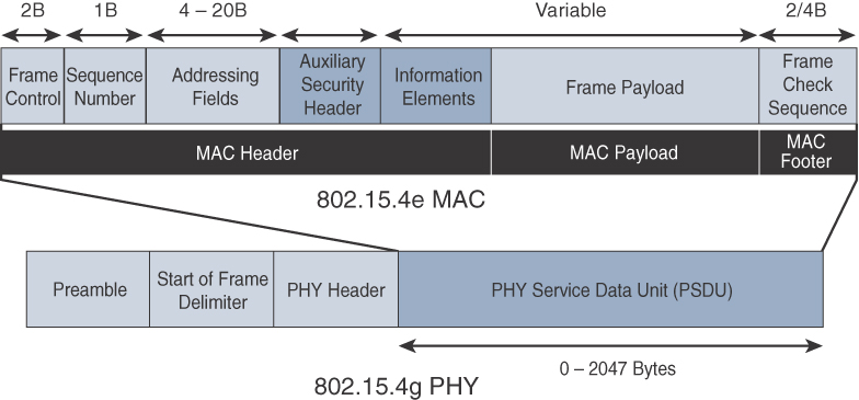
The 802.15.4e MAC is similar to the 802.15.4 MAC in Figure 4-6. The main changes shown in the IEEE 802.15.4e header in Figure 4-9 are the presence of the Auxiliary Security Header and Information Elements field. The Auxiliary Security header provides for the encryption of the data frame. This field is optionally supported in both 802.15.4e-2012 and 802.15.4, starting with the 802.15.4-2006 specification, as shown in Figure 4-8. As discussed earlier in this section, the IE field contains one or more information elements that allow for additional information to be exchanged at the MAC layer.
Topology
Deployments of IEEE 802.15.4g-2012 are mostly based on a mesh topology. This is because a mesh topology is typically the best choice for use cases in the industrial and smart cities areas where 802.15.4g-2012 is applied. A mesh topology allows deployments to be done in urban or rural areas, expanding the distance between nodes that can relay the traffic of other nodes. Considering the use cases addressed by this technology, powered nodes have been the primary targets of implementations. Support for battery-powered nodes with a long lifecycle requires optimized Layer 2 forwarding or Layer 3 routing protocol implementations. This provides an extra level of complexity but is necessary in order to cope with sleeping battery-powered nodes.
Security
Both IEEE 802.15.4g and 802.15.4e inherit their security attributes from the IEEE 802.15.4-2006 specification. Therefore, encryption is provided by AES, with a 128-bit key. In addition to the Auxiliary Security Header field initially defined in 802.15.4-2006, a secure acknowledgement and a secure Enhanced Beacon field complete the MAC layer security. Figure 4-10 shows a high-level overview of the security associated with an IEEE 802.15.4e MAC frame.

The full frame in Figure 4-10 gets authenticated through the MIC at the end of frame. The MIC is a unique value that is calculated based on the frame contents. (The MIC is discussed in more detail earlier in this chapter.) The Security Header field denoted in Figure 4-10 is composed of the Auxiliary Security field and one or more Information Elements fields. Integration of the Information Elements fields allows for the adoption of additional security capabilities, such as the IEEE 802.15.9 Key Management Protocol (KMP) specification. KMP provides a means for establishing keys for robust datagram security. Without key management support, weak keys are often the result, leaving the security system open to attack.
Competitive Technologies
Competitive technologies to IEEE 802.15.4g and 802.15.4e parallel the technologies that also compete with IEEE 802.15.4, such as DASH7. (DASH7 is discussed earlier in this chapter.) In many ways, 802.15.4 and its various flavors of upper-layer protocols, as shown in Table 4-2, can be seen as competitors as well. IEEE 802.15.4 is well established and already deployed in many scenarios, mostly indoors.
IEEE 802.15.4g and 802.15.4e Conclusions
It is important to remember that IEEE 802.15.4g and 802.15.4e are simply amendments to the IEEE 802.15.4 standard. They are mature specifications that are integrated into IEEE 802.15.4-2015. They have been successfully deployed in real-world scenarios, and already support millions of endpoints. IEEE 802.15.4g focuses mainly on improvements to the PHY layer, while IEEE 802.15.4e targets the MAC layer. These improvements overcome many of the disadvantages of IEEE 802.15.4, such as latency and vulnerability to multipath fading. In addition, provisions in these amendments make them better suited to handle the unique deployment models in the areas of smart grid/utilities and smart cities.
The Wi-SUN Alliance is an important industry alliance that provides interoperability and certification for industry implementations. Utilizing 802.15.4g as a foundation, the alliance releases profiles, such as the FAN profile, to help promote the adoption of the technology while guaranteeing interoperability between vendors. You should expect to see increasing use of both 802.15.4g and 802.15.4e, especially in the smart grid and smart cities verticals of IoT, where they have already seen strong adoption.
IEEE 1901.2a
While most of the constrained network technologies relate to wireless, IEEE 1901.2a-2013 is a wired technology that is an update to the original IEEE 1901.2 specification. This is a standard for Narrowband Power Line Communication (NB-PLC). NB-PLC leverages a narrowband spectrum for low power, long range, and resistance to interference over the same wires that carry electric power. NB-PLC is often found in use cases such as the following:
![]() Smart metering: NB-PLC can be used to automate the reading of utility meters, such as electric, gas, and water meters. This is true particularly in Europe, where PLC is the preferred technology for utilities deploying smart meter solutions.
Smart metering: NB-PLC can be used to automate the reading of utility meters, such as electric, gas, and water meters. This is true particularly in Europe, where PLC is the preferred technology for utilities deploying smart meter solutions.
![]() Distribution automation: NB-PLC can be used for distribution automation, which involves monitoring and controlling all the devices in the power grid.
Distribution automation: NB-PLC can be used for distribution automation, which involves monitoring and controlling all the devices in the power grid.
![]() Public lighting: A common use for NB-PLC is with public lighting—the lights found in cities and along streets, highways, and public areas such as parks.
Public lighting: A common use for NB-PLC is with public lighting—the lights found in cities and along streets, highways, and public areas such as parks.
![]() Electric vehicle charging stations: NB-PLC can be used for electric vehicle charging stations, where the batteries of electric vehicles can be recharged.
Electric vehicle charging stations: NB-PLC can be used for electric vehicle charging stations, where the batteries of electric vehicles can be recharged.
![]() Microgrids: NB-PLC can be used for microgrids, local energy grids that can disconnect from the traditional grid and operate independently.
Microgrids: NB-PLC can be used for microgrids, local energy grids that can disconnect from the traditional grid and operate independently.
![]() Renewable energy: NB-PLC can be used in renewable energy applications, such as solar, wind power, hydroelectric, and geothermal heat.
Renewable energy: NB-PLC can be used in renewable energy applications, such as solar, wind power, hydroelectric, and geothermal heat.
All these use cases require a direct connection to the power grid. So it makes sense to transport IoT data across power grid connections that are already in place.
Multiple PLC standards exist, but the formation of IEEE 1901.2a was driven by the absence of a low-frequency PLC solution below 500 kHz. IEEE 1901.2a specifies the use of both alternating and direct current electric power lines. Low- and medium-voltage lines in both indoor and outdoor environments are supported, along with multiple-mile distances. Data rates can scale up to 500 kbps. The IEEE 1901.2a PHY and MAC layers can be mixed with IEEE 802.15.4g/e on endpoints, offering a dual-PHY solution for some use cases.
Standardization and Alliances
The first generations of NB-PLC implementations have generated a lot of interest from utilities in Europe but have often suffered from poor reliability, low throughput (in the range of a few hundred bits per second to a maximum of 2 kbps), lack of manageability, and poor interoperability. This has led several organizations (including standards bodies and alliance consortiums) to develop their own specifications for new generations of NB-PLC technologies. Most recent NB-PLC standards are based on orthogonal frequency-division multiplexing (OFDM). However, different standards from various vendors competing with one another have created a fragmented market. OFDM encodes digital data on multiple carrier frequencies. This provides several parallel streams that suffer less from high frequency attenuation in copper wire and narrowband interference.
The IEEE 1901.2 working group published the IEEE 1901.2a specification in November 2013. Originally leveraging the work done by the G3-PLC (now ITU G.9903) and PRIME (now ITU G.9904) working groups, the IEEE 1901.2 working group only looked at standardizing the NB-PLC PHY and MAC layers (as defined by the IEEE charter and done in other IEEE standards) independently of the upper layers. This differs from G.9903 and G.9904, which were developed for a single use case, smart metering, and focused on running specific application protocols for smart meters.
The IEEE 1901.2a standard does have some alignment with the latest developments done in other IEEE working groups. For example, using the 802.15.4e Information Element fields eases support for IEEE 802.15.9 key management. In addition, a dual-PHY approach is possible when combined with IEEE 802.15.4g/e on endpoints.
The HomePlug Alliance was one of the main industry organizations that drove the promotion and certification of PLC technologies, with IEEE 1901.2a being part of its HomePlug Netricity program. In 2016, the HomePlug Alliance made the decision to offer the alliance’s broadband power line networking technology to a broader audience by making its technical specifications publicly available. It has also partnered with other alliances on continuing ongoing work. The HomePlug Alliance has struck a liaison agreement with the Wi-SUN Alliance with the goal of enabling hybrid smart grid networks that support both wireless and power line–wired connectivity. For more information on the HomePlug Alliance and Netricity, see www.homeplug.org.
Physical Layer
NB-PLC is defined for frequency bands from 3 to 500 kHz. Much as with wireless sub-GHz frequency bands, regional regulations and definitions apply to NB-PLC. The IEEE 1901.2 working group has integrated support for all world regions in order to develop a worldwide standard. Specifications include support for CENELEC A and B bands, US FCC-Low and FCC-above-CENELEC, and Japan ARIB bands. CENELEC is the French Comité Européen de Normalisation Électrotechnique, which in English translates to European Committee for Electrotechnical Standardization. This organization is responsible for standardization in the area of electrical engineering for Europe. The CENELEC A and B bands refer to 9–95 kHz and 95–125 kHz, respectively. The FCC is the Federal Communications Commission, a US government organization that regulates interstate and international communications by radio, television, wire, satellite, and cable. The FCC-Low band encompasses 37.5–117.1875 kHz, and the FCC-above-CENELEC band is 154.6875–487.5 kHz. The FCC-above-CENELEC band may become the most useful frequency due to its higher throughput and reduced interference.
Figure 4-11 shows the various frequency bands for NB-PLC. Notice that the most well-known bands are regulated by CENELEC and the FCC, but the Japan Association of Radio Industries and Businesses (ARIB) band is also present. The two ARIB frequency bands are ARIB 1, 37.5–117.1875 kHz, and ARIB 2, 154.6875–403.125 kHz.

Based on OFDM, the IEEE 1901.2 specification leverages the best from other NB-PLC OFDM technologies that were developed previously. Therefore, IEEE 1901.2a supports the largest set of coding and enables both robustness and throughput. The standard includes tone maps and modulations, such as robust modulation (ROBO), differential binary phase shift keying (DBPSK), differential quadrature phase shift keying (DQPSK), differential 8-point phase shift keying (D8PSK) for all bands, and optionally 16 quadrature amplitude modulation (16QAM) for some bands. ROBO mode transmits redundant information on multiple carriers, and DBPSK, DQPSK, and D8PSK are all variations of phase shift keying, where the phase of a signal is changed to signal a binary data transmission. ROBO utilizes QPSK modulation, and its throughput depends on the degree to which coding is repeated across streams. For example, standard ROBO uses a repetition of 4, and Super-ROBO utilizes a repetition of 6.
With IEEE 1901.2a, the data throughput rate has the ability to dynamically change, depending on the modulation type and tone map. For CENELEC A band, the data rate ranges from 4.5 kbps in ROBO mode to 46 kbps with D8PSK modulation. For the FCC-above-CENELEC frequencies, throughput varies from 21 kbps in ROBO mode to a maximum of 234 kbps using D8PSK.
One major difference between IEEE 802.15.4g/e and IEEE 1901.2a is the full integration of different types of modulation and tone maps by a single PHY layer in the IEEE 1901.2a specification. IEEE 802.15.4g/e doesn’t really define a multi-PHY management algorithm. The PHY payload size can change dynamically, based on channel conditions in IEEE 1901.2a. Therefore, MAC sublayer segmentation is implemented. If the size of the MAC payload is too large to fit within one PHY service data unit (PSDU), the MAC payload is partitioned into smaller segments. MAC payload segmentation is done by dividing the MAC payload into multiple smaller amounts of data (segments), based on PSDU size. The segmentation may require the addition of padding bytes to the last payload segment so that the final MPDU fills the PSDU. All forms of addressing (unicast and broadcast) are subject to segmentation.
MAC Layer
The MAC frame format of IEEE 1901.2a is based on the IEEE 802.15.4 MAC frame but integrates the latest IEEE 802.15.4e-2012 amendment, which enables key features to be supported. (For more information on the 802.15.4 MAC frame format, refer to Figure 4-6. For the 802.15.4e MAC frame format, see Figure 4-9.) One of the key components brought from 802.15.4e to IEEE 1901.2a is information elements. With IE support, additional capabilities, such as IEEE 802.15.9 Key Management Protocol and SSID, are supported. Figure 4-12 provides an overview of the general MAC frame format for IEEE 1901.2. Note that the numeric value above each field in the frame shows the size of the field, in bytes.
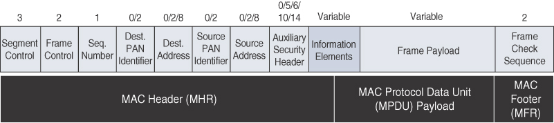
As shown in Figure 4-12, IEEE 1901.2 has a Segment Control field. This is a new field that was not present in our previous discussions of the MAC frame for 802.15.4 and 802.15.4e. This field handles the segmentation or fragmentation of upper-layer packets with sizes larger than what can be carried in the MAC protocol data unit (MPDU). The rest of the fields are discussed earlier in this chapter and shown in Figures 4-6, 4-8, and 4-9. Refer to these figures if you need further information on these fields.
Topology
Use cases and deployment topologies for IEEE 1901.2a are tied to the physical power lines. As with wireless technologies, signal propagation is limited by factors such as noise, interference, distortion, and attenuation. These factors become more prevalent with distance, so most NB-PLC deployments use some sort of mesh topology. Mesh networks offer the advantage of devices relaying the traffic of other devices so longer distances can be segmented. Figure 4-13 highlights a network scenario in which a PLC mesh network is applied to a neighborhood.
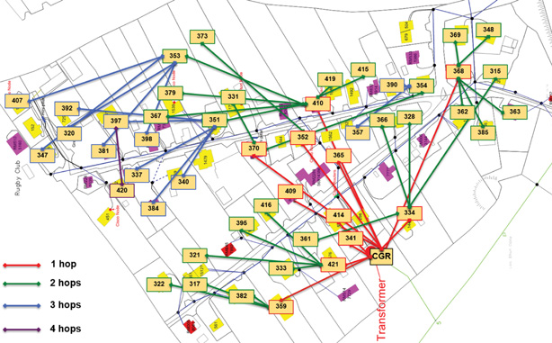
The IEEE 1901.2a standard offers the flexibility to run any upper-layer protocol. So, implementations of IPv6 6LoWPAN and RPL IPv6 protocols are supported. These protocols enable the use of network layer routing to create mesh networks over PLC. (For more information on 6LoWPAN and RPL, see Chapter 5.)
Security
IEEE 1901.2a security offers similar features to IEEE 802.15.4g. Encryption and authentication are performed using AES. In addition, IEEE 1901.2a aligns with 802.15.4g in its ability to support the IEEE 802.15.9 Key Management Protocol. However, some differences exist. These differences are mostly tied to the PHY layer fragmentation capabilities of IEEE 1901.2a and include the following:
![]() The Security Enabled bit in the Frame Control field should be set in all MAC frames carrying segments of an encrypted frame. (The Security Enabled bit is shown in Figure 4-8.)
The Security Enabled bit in the Frame Control field should be set in all MAC frames carrying segments of an encrypted frame. (The Security Enabled bit is shown in Figure 4-8.)
![]() If data encryption is required, it should be done before packet segmentation. During packet encryption, the Segment Control field should not be included in the input to the encryption algorithm.
If data encryption is required, it should be done before packet segmentation. During packet encryption, the Segment Control field should not be included in the input to the encryption algorithm.
![]() On the receiver side, the data decryption is done after packet reassembly.
On the receiver side, the data decryption is done after packet reassembly.
![]() When security is enabled, the MAC payload is composed of the ciphered payload and the message integrity code (MIC) authentication tag for non-segmented payloads. If the payload is segmented, the MIC is part of the last packet (segment) only. The MIC authentication is computed using only information from the MHR of the frame carrying the first segment.
When security is enabled, the MAC payload is composed of the ciphered payload and the message integrity code (MIC) authentication tag for non-segmented payloads. If the payload is segmented, the MIC is part of the last packet (segment) only. The MIC authentication is computed using only information from the MHR of the frame carrying the first segment.
Competitive Technologies
In the domain of NB-PLC, two technologies compete against IEEE 1901.2a: G3-PLC (now ITU G.9903) and PRIME (now ITU G.9904). Both of these technologies were initially developed to address a single use case: smart metering deployment in Europe over the CENELEC A band.
As mentioned previously, IEEE 1901.2a leverages portions of G3-PLC and PRIME, and it also competes with them. More specifically, G3-PLC is really close to IEEE 1901.2. The main differences include the fact that G3-PLC mandates data link layer protocol options for bootstrapping and allocating device addresses, and it is incompatible with IEEE 802.15.4g/e and an end-to-end IPv6 model. This means there is no information element support and no global IPv6 address support. PRIME is more like an ATM approach, with a Layer 7 protocol (that is, DLMS/COSEM) that runs directly on top of Layer 2. Adding IP support requires that Layer 3 protocols be added.
Following the IEEE 1901.2 working group efforts, new versions of G3-PLC and PRIME were published. These newer versions add a similar feature set, such as FCC and ARIB band support, ROBO for PRIME, and Super-ROBO and 16QAM for G3-PLC. As these competitive technologies continue to evolve and borrow from one another, it seems there might be a convergence toward compatibility at some point in the future.
IEEE 1901.2a Conclusions
IEEE 1901.2a is an open PHY and MAC standard approach to enable the use of Narrowband Power Line Communication. The set of use cases for this standard depends on and also benefits from the physical power lines that interconnect the devices.
The IEEE 1901.2a standard leverages the earlier standards G3-PLC (now ITU G.9903) and PRIME (now ITU G.9904). Supporting a wide range of frequencies at the PHY layer, IEEE 1901.2a also has a feature-rich MAC layer, based on 802.15.4. This flexibility in the MAC layer lends readily to the support of mesh topologies.
The HomePlug Alliance’s Netricity program and the liaison agreement with the Wi-SUN Alliance provide industry support for IEEE 1901.2a by means of a profile definition and a certification program. However, IEEE 1901.2a faces competition from G3-PLC and PRIME as they are more established standards that continue to evolve.
Widespread adoption of IEEE 1901.2a depends on implementation from vendors. Most chipsets offer support for IEEE 1901.2a, G3-PLC, and PRIME because they are the three competitive OFDM-based PLC technologies. If end-to-end IP communication or dual-PHY integration with IEEE 802.15.4g/e is expected, IEEE 1901.2a becomes the protocol of choice.
IEEE 802.11ah
In unconstrained networks, IEEE 802.11 Wi-Fi is certainly the most successfully deployed wireless technology. This standard is a key IoT wireless access technology, either for connecting endpoints such as fog computing nodes, high-data-rate sensors, and audio or video analytics devices or for deploying Wi-Fi backhaul infrastructures, such as outdoor Wi-Fi mesh in smart cities, oil and mining, or other environments. However, Wi-Fi lacks sub-GHz support for better signal penetration, low power for battery-powered nodes, and the ability to support a large number of devices. For these reasons, the IEEE 802.11 working group launched a task group named IEEE 802.11ah to specify a sub-GHz version of Wi-Fi. Three main use cases are identified for IEEE 802.11ah:
![]() Sensors and meters covering a smart grid: Meter to pole, environmental/agricultural monitoring, industrial process sensors, indoor healthcare system and fitness sensors, home and building automation sensors
Sensors and meters covering a smart grid: Meter to pole, environmental/agricultural monitoring, industrial process sensors, indoor healthcare system and fitness sensors, home and building automation sensors
![]() Backhaul aggregation of industrial sensors and meter data: Potentially connecting IEEE 802.15.4g subnetworks
Backhaul aggregation of industrial sensors and meter data: Potentially connecting IEEE 802.15.4g subnetworks
![]() Extended range Wi-Fi: For outdoor extended-range hotspot or cellular traffic offloading when distances already covered by IEEE 802.11a/b/g/n/ac are not good enough
Extended range Wi-Fi: For outdoor extended-range hotspot or cellular traffic offloading when distances already covered by IEEE 802.11a/b/g/n/ac are not good enough
Standardization and Alliances
In July 2010, the IEEE 802.11 working group decided to work on an “industrial Wi-Fi” and created the IEEE 802.11ah group. The 802.11ah specification would operate in unlicensed sub-GHz frequency bands, similar to IEEE 802.15.4 and other LPWA technologies.
The industry organization that promotes Wi-Fi certifications and interoperability for 2.4 GHz and 5 GHz products is the Wi-Fi Alliance. The Wi-Fi Alliance is a similar body to the Wi-SUN Alliance. For more information on the Wi-Fi Alliance, see its webpage, at www.wi-fi.org
For the 802.11ah standard, the Wi-Fi Alliance defined a new brand called Wi-Fi HaLow. This marketing name is based on a play on words between “11ah” in reverse and “low power.” It is similar to the word “hello” but it is pronounced “hay-low.” The HaLow brand exclusively covers IEEE 802.11ah for sub-GHz device certification. You can think of Wi-Fi HaLow as a commercial designation for products incorporating IEEE 802.11ah technology. For more information on W-Fi HaLow, visit www.wi-fi.org/discover-wi-fi/wi-fi-halow.
Physical Layer
IEEE 802.11ah essentially provides an additional 802.11 physical layer operating in unlicensed sub-GHz bands. For example, various countries and regions use the following bands for IEEE 802.11ah: 868–868.6 MHz for EMEAR, 902–928 MHz and associated subsets for North America and Asia-Pacific regions, and 314–316 MHz, 430–434 MHz, 470–510 MHz, and 779–787 MHz for China.
Based on OFDM modulation, IEEE 802.11ah uses channels of 2, 4, 8, or 16 MHz (and also 1 MHz for low-bandwidth transmission). This is one-tenth of the IEEE 802.11ac channels, resulting in one-tenth of the corresponding data rates of IEEE 802.11ac. The IEEE 802.11ac standard is a high-speed wireless LAN protocol at the 5 GHz band that is capable of speeds up to 1 Gbps. While 802.11ah does not approach this transmission speed (as it uses one-tenth of 802.11ac channel width, it reaches one-tenth of 802.11ac speed), it does provide an extended range for its lower speed data. For example, at a data rate of 100 kbps, the outdoor transmission range for IEEE 802.11ah is expected to be 0.62 mile.
MAC Layer
The IEEE 802.11ah MAC layer is optimized to support the new sub-GHz Wi-Fi PHY while providing low power consumption and the ability to support a larger number of endpoints. Enhancements and features specified by IEEE 802.11ah for the MAC layer include the following:
![]() Number of devices: Has been scaled up to 8192 per access point.
Number of devices: Has been scaled up to 8192 per access point.
![]() MAC header: Has been shortened to allow more efficient communication.
MAC header: Has been shortened to allow more efficient communication.
![]() Null data packet (NDP) support: Is extended to cover several control and management frames. Relevant information is concentrated in the PHY header and the additional overhead associated with decoding the MAC header and data payload is avoided. This change makes the control frame exchanges efficient and less power-consuming for the receiving stations.
Null data packet (NDP) support: Is extended to cover several control and management frames. Relevant information is concentrated in the PHY header and the additional overhead associated with decoding the MAC header and data payload is avoided. This change makes the control frame exchanges efficient and less power-consuming for the receiving stations.
![]() Grouping and sectorization: Enables an AP to use sector antennas and also group stations (distributing a group ID). In combination with RAW and TWT, this mechanism reduces contention in large cells with many clients by restricting which group, in which sector, can contend during which time window. (Sectors are described in more detail in the following section.)
Grouping and sectorization: Enables an AP to use sector antennas and also group stations (distributing a group ID). In combination with RAW and TWT, this mechanism reduces contention in large cells with many clients by restricting which group, in which sector, can contend during which time window. (Sectors are described in more detail in the following section.)
![]() Restricted access window (RAW): Is a control algorithm that avoids simultaneous transmissions when many devices are present and provides fair access to the wireless network. By providing more efficient access to the medium, additional power savings for battery-powered devices can be achieved, and collisions are reduced.
Restricted access window (RAW): Is a control algorithm that avoids simultaneous transmissions when many devices are present and provides fair access to the wireless network. By providing more efficient access to the medium, additional power savings for battery-powered devices can be achieved, and collisions are reduced.
![]() Target wake time (TWT): Reduces energy consumption by permitting an access point to define times when a device can access the network. This allows devices to enter a low-power state until their TWT time arrives. It also reduces the probability of collisions in large cells with many clients.
Target wake time (TWT): Reduces energy consumption by permitting an access point to define times when a device can access the network. This allows devices to enter a low-power state until their TWT time arrives. It also reduces the probability of collisions in large cells with many clients.
![]() Speed frame exchange: Enables an AP and endpoint to exchange frames during a reserved transmit opportunity (TXOP). This reduces contention on the medium, minimizes the number of frame exchanges to improve channel efficiency, and extends battery life by keeping awake times short.
Speed frame exchange: Enables an AP and endpoint to exchange frames during a reserved transmit opportunity (TXOP). This reduces contention on the medium, minimizes the number of frame exchanges to improve channel efficiency, and extends battery life by keeping awake times short.
You can see from this feature list that the 802.11ah MAC layer is focused on power consumption and mechanisms to allow low-power Wi-Fi stations to wake up less often and operate more efficiently. This sort of MAC layer is ideal for IoT devices that often produce short, low-bit-rate transmissions.
Topology
While IEEE 802.11ah is deployed as a star topology, it includes a simple hops relay operation to extend its range. This relay option is not capped, but the IEEE 802.11ah task group worked on the assumption of two hops. It allows one 802.11ah device to act as an intermediary and relay data to another. In some ways, this is similar to a mesh, and it is important to note that the clients and not the access point handle the relay function.
This relay operation can be combined with a higher transmission rate or modulation and coding scheme (MCS). This means that a higher transmit rate is used by relay devices talking directly to the access point. The transmit rate reduces as you move further from the access point via relay clients. This ensures an efficient system that limits transmission speeds at the edge of the relays so that communications close to the AP are not negatively affected.
Sectorization is a technique that involves partitioning the coverage area into several sectors to get reduced contention within a certain sector. This technique is useful for limiting collisions in cells that have many clients. This technique is also often necessary when the coverage area of 802.11ah access points is large, and interference from neighboring access points is problematic. Sectorization uses an antenna array and beam-forming techniques to partition the cell-coverage area. Figure 4-14 shows an example of 802.11ah sectorization.

Security
No additional security has been identified for IEEE 802.11ah compared to other IEEE 802.11 specifications. (The other IEEE protocols are discussed earlier in this chapter.) These protocols include IEEE 802.15.4, IEEE 802.15.4e, and IEEE 1901.2a, and the security information for them is also applicable to IEEE 802.11ah.
Competitive Technologies
Competitive technologies to IEEE 802.11ah are IEEE 802.15.4 and IEEE 802.15.4e, along with the competitive technologies highlighted in each of their sections. (For more information on these competing technologies, see the sections “IEEE 802.15.4” and “IEEE 802.15.4g and IEEE 802.15.4e,” earlier in this chapter.)
IEEE 802.11ah Conclusions
The IEEE 802.11ah access technology is an ongoing effort of the IEEE 802.11 working group to define an “industrial Wi-Fi.” Currently, this standard is just at the beginning of its evolution, and it is not clear how the market will react to this new Wi-Fi standard.
This specification offers a longer range than traditional Wi-Fi technologies and provides good support for low-power devices that need to send smaller bursts of data at lower speeds. At the same time, it has the ability to scale to higher speeds as well.
IEEE 802.11ah is quite different in terms of current products and the existing Wi-Fi technologies in the 2.4 GHz and 5 GHz frequency bands. To gain broad adoption and compete against similar technologies in this space, it will need an ecosystem of products and solutions that can be configured and deployed at a low cost.
LoRaWAN
In recent years, a new set of wireless technologies known as Low-Power Wide-Area (LPWA) has received a lot of attention from the industry and press. Particularly well adapted for long-range and battery-powered endpoints, LPWA technologies open new business opportunities to both services providers and enterprises considering IoT solutions. This section discusses an example of an unlicensed-band LPWA technology, known as LoRaWAN, and the next section, “NB-IoT and Other LTE Variations,” reviews licensed-band alternatives from the 3rd Generation Partnership Project (3GPP).
Note
Other technologies could have been covered in this section of the book from an LPWA perspective, but currently this part of the IoT world is still evolving, and there are a lot of available options. We chose to cover LoRaWAN because it is one of the few options that is established, and it is backed by an industry alliance supported by a substantial number of companies.
Standardization and Alliances
Initially, LoRa was a physical layer, or Layer 1, modulation that was developed by a French company named Cycleo. Later, Cycleo was acquired by Semtech. Optimized for long-range, two-way communications and low power consumption, the technology evolved from Layer 1 to a broader scope through the creation of the LoRa Alliance. For more information on the LoRa Alliance, visit www.lora-alliance.org.
The LoRa Alliance quickly achieved industry support and currently has hundreds of members. Published LoRaWAN specifications are open and can be accessed from the LoRa Alliance website.
Semtech LoRa as a Layer 1 PHY modulation technology is available through multiple chipset vendors. To differentiate from the physical layer modulation known as LoRa, the LoRa Alliance uses the term LoRaWAN to refer to its architecture and its specifications that describe end-to-end LoRaWAN communications and protocols.
Figure 4-15 provides a high-level overview of the LoRaWAN layers. In this figure, notice that Semtech is responsible for the PHY layer, while the LoRa Alliance handles the MAC layer and regional frequency bands.
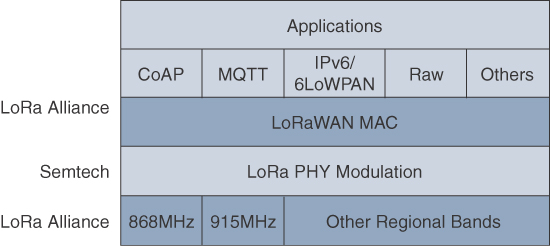
Overall, the LoRa Alliance owns and manages the roadmap and technical development of the LoRaWAN architecture and protocol. This alliance also handles the LoRaWAN endpoint certification program and technology promotion through its certification and marketing committees.
Physical Layer
Semtech LoRa modulation is based on chirp spread spectrum modulation, which trades a lower data rate for receiver sensitivity to significantly increase the communication distance. In addition, it allows demodulation below the noise floor, offers robustness to noise and interference, and manages a single channel occupation by different spreading factors. This enables LoRa devices to receive on multiple channels in parallel.
LoRaWAN 1.0.2 regional specifications describe the use of the main unlicensed sub-GHz frequency bands of 433 MHz, 779–787 MHz, 863–870 MHz, and 902–928 MHz, as well as regional profiles for a subset of the 902–928 MHz bandwidth. For example, Australia utilizes 915–928 MHz frequency bands, while South Korea uses 920–923 MHz and Japan uses 920–928 MHz.
Note
Semtech LoRa chipsets support additional frequency bands, such as 169 MHz, that are not supported by LoRaWAN specifications. Additional regional profiles and bands are under development and are being considered by the LoRa Alliance.
Understanding LoRa gateways is critical to understanding a LoRaWAN system. A LoRa gateway is deployed as the center hub of a star network architecture. It uses multiple transceivers and channels and can demodulate multiple channels at once or even demodulate multiple signals on the same channel simultaneously. LoRa gateways serve as a transparent bridge relaying data between endpoints, and the endpoints use a single-hop wireless connection to communicate with one or many gateways.
The data rate in LoRaWAN varies depending on the frequency bands and adaptive data rate (ADR). ADR is an algorithm that manages the data rate and radio signal for each endpoint. The ADR algorithm ensures that packets are delivered at the best data rate possible and that network performance is both optimal and scalable. Endpoints close to the gateways with good signal values transmit with the highest data rate, which enables a shorter transmission time over the wireless network, and the lowest transmit power. Meanwhile, endpoints at the edge of the link budget communicate at the lowest data rate and highest transmit power.
Note
LoRaWAN best practices recommend the use of ADR for fixed endpoints, and a fixed data rate or spreading factor for mobile endpoints. Data rate management is not practical when mobile endpoints cause quick changes in their radio environment.
An important feature of LoRa is its ability to handle various data rates via the spreading factor. Devices with a low spreading factor (SF) achieve less distance in their communications but transmit at faster speeds, resulting in less airtime. A higher SF provides slower transmission rates but achieves a higher reliability at longer distances. Table 4-4 illustrates how LoRaWAN data rates can vary depending on the associated spreading factor for the two main frequency bands, 863–870 MHz and 902–928 MHz.
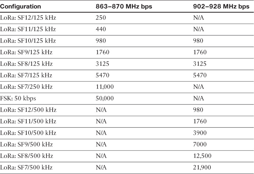
In Table 4-4, notice the relationship between SF and data rate. For example, at an SF value of 12 for 125 kHz of channel bandwidth, the data rate is 250 bps. However, when the SF is decreased to a value of 7, the data rate increases to 5470 bps.
Channel bandwidth values of 125 kHz, 250 kHz, and 500 kHz are also evident in Table 4-4. The effect of increasing the bandwidth is that faster data rates can be achieved for the same spreading factor.
MAC Layer
As mentioned previously, the MAC layer is defined in the LoRaWAN specification. This layer takes advantage of the LoRa physical layer and classifies LoRaWAN endpoints to optimize their battery life and ensure downstream communications to the LoRaWAN endpoints. The LoRaWAN specification documents three classes of LoRaWAN devices:
![]() Class A: This class is the default implementation. Optimized for battery-powered nodes, it allows bidirectional communications, where a given node is able to receive downstream traffic after transmitting. Two receive windows are available after each transmission.
Class A: This class is the default implementation. Optimized for battery-powered nodes, it allows bidirectional communications, where a given node is able to receive downstream traffic after transmitting. Two receive windows are available after each transmission.
![]() Class B: This class was designated “experimental” in LoRaWAN 1.0.1 until it can be better defined. A Class B node or endpoint should get additional receive windows compared to Class A, but gateways must be synchronized through a beaconing process.
Class B: This class was designated “experimental” in LoRaWAN 1.0.1 until it can be better defined. A Class B node or endpoint should get additional receive windows compared to Class A, but gateways must be synchronized through a beaconing process.
![]() Class C: This class is particularly adapted for powered nodes. This classification enables a node to be continuously listening by keeping its receive window open when not transmitting.
Class C: This class is particularly adapted for powered nodes. This classification enables a node to be continuously listening by keeping its receive window open when not transmitting.
LoRaWAN messages, either uplink or downlink, have a PHY payload composed of a 1-byte MAC header, a variable-byte MAC payload, and a MIC that is 4 bytes in length. The MAC payload size depends on the frequency band and the data rate, ranging from 59 to 230 bytes for the 863–870 MHz band and 19 to 250 bytes for the 902–928 MHz band. Figure 4-16 shows a high-level LoRaWAN MAC frame format.
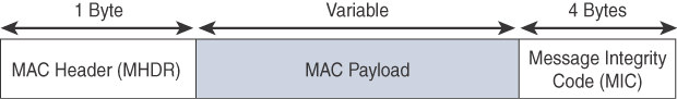
In version 1.0.x, LoRaWAN utilizes six MAC message types. LoRaWAN devices use join request and join accept messages for over-the-air (OTA) activation and joining the network. The other message types are unconfirmed data up/down and confirmed data up/down. A “confirmed” message is one that must be acknowledged, and “unconfirmed” signifies that the end device does not need to acknowledge. “up/down” is simply a directional notation identifying whether the message flows in the uplink or downlink path. Uplink messages are sent from endpoints to the network server and are relayed by one or more LoRaWAN gateways. Downlink messages flow from the network server to a single endpoint and are relayed by only a single gateway. Multicast over LoRaWAN is being considered for future versions.
LoRaWAN endpoints are uniquely addressable through a variety of methods, including the following:
![]() An endpoint can have a global end device ID or DevEUI represented as an IEEE EUI-64 address.
An endpoint can have a global end device ID or DevEUI represented as an IEEE EUI-64 address.
![]() An endpoint can have a global application ID or AppEUI represented as an IEEE EUI-64 address that uniquely identifies the application provider, such as the owner, of the end device.
An endpoint can have a global application ID or AppEUI represented as an IEEE EUI-64 address that uniquely identifies the application provider, such as the owner, of the end device.
![]() In a LoRaWAN network, endpoints are also known by their end device address, known as a DevAddr, a 32-bit address. The 7 most significant bits are the network identifier (NwkID), which identifies the LoRaWAN network. The 25 least significant bits are used as the network address (NwkAddr) to identify the endpoint in the network.
In a LoRaWAN network, endpoints are also known by their end device address, known as a DevAddr, a 32-bit address. The 7 most significant bits are the network identifier (NwkID), which identifies the LoRaWAN network. The 25 least significant bits are used as the network address (NwkAddr) to identify the endpoint in the network.
The LoRa Alliance maintains a list of companies that have registered for network identifiers (NwkIDs). The LoRa Alliance also allocates new NwkIDs. When the LoRaWAN 1.1 specification is released, a NetID field will uniquely identify a network operator. This code is also managed by the LoRa Alliance. The seven least significant bits of the NetID contain the NwkID. The NwkIDs in the DevAddr field and the NetID field are the same so the 7 most significant bits found in the DevAddr field must match the 7 least significant bits of the NetID.
Topology
LoRaWAN topology is often described as a “star of stars” topology. As shown in Figure 4-17, the infrastructure consists of endpoints exchanging packets through gateways acting as bridges, with a central LoRaWAN network server. Gateways connect to the backend network using standard IP connections, and endpoints communicate directly with one or more gateways.
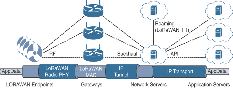
In Figure 4-17, LoRaWAN endpoints transport their selected application data over the LoRaWAN MAC layer on top of one of the supported PHY layer frequency bands. The application data is contained in upper protocol layers. These upper layers are not the responsibility of the LoRa Alliance, but best practices may be developed and recommended. These upper layers could just be raw data on top of the LoRaWAN MAC layer, or the data could be stacked in multiple protocols. For example, you could have upper-layer protocols, such as ZigBee Control Layer (ZCL), Constrained Application Protocol (CoAP), or Message Queuing Telemetry Transport (MQTT), with or without an IPv6/6LoWPAN layer. (The CoAP and MQTT protocols are covered in Chapter 6.)
Figure 4-17 also shows how LoRaWAN gateways act as bridges that relay between endpoints and the network servers. Multiple gateways can receive and transport the same packets. When duplicate packets are received, de-duplication is a function of the network server.
Semtech, developer of the LoRa PHY, has specified two generations of LoRaWAN gateways. The first generation was simple, and the next generation, known as version 2, adds new features, such as geolocation. Geolocation works by having version 2 LoRaWAN gateways share an accurate time source and then adding a high-resolution timestamp to each received LoRa packet. The endpoint’s geolocation can be determined by using time differential of arrival (TDoA) algorithms.
The LoRaWAN network server manages the data rate and radio frequency (RF) of each endpoint through the adaptive data rate (ADR) algorithm. ADR is a key component of the network scalability, performance, and battery life of the endpoints. The LoRaWAN network server forwards application data to the application servers, as depicted in Figure 4-17.
In future versions of the LoRaWAN specification, roaming capabilities between LoRaWAN network servers will be added. These capabilities will enable mobile endpoints to connect and roam between different LoRaWAN network infrastructures.
Security
Security in a LoRaWAN deployment applies to different components of the architecture, as detailed in Figure 4-18. LoRaWAN endpoints must implement two layers of security, protecting communications and data privacy across the network.
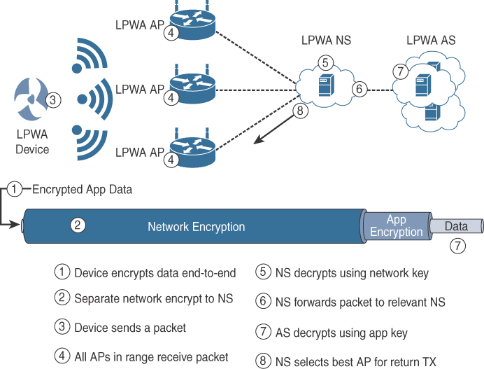
The first layer, called “network security” but applied at the MAC layer, guarantees the authentication of the endpoints by the LoRaWAN network server. Also, it protects LoRaWAN packets by performing encryption based on AES.
Each endpoint implements a network session key (NwkSKey), used by both itself and the LoRaWAN network server. The NwkSKey ensures data integrity through computing and checking the MIC of every data message as well as encrypting and decrypting MAC-only data message payloads.
The second layer is an application session key (AppSKey), which performs encryption and decryption functions between the endpoint and its application server. Furthermore, it computes and checks the application-level MIC, if included. This ensures that the LoRaWAN service provider does not have access to the application payload if it is not allowed that access.
Endpoints receive their AES-128 application key (AppKey) from the application owner. This key is most likely derived from an application-specific root key exclusively known to and under the control of the application provider.
For production deployments, it is expected that the LoRaWAN gateways are protected as well, for both the LoRaWAN traffic and the network management and operations over their backhaul link(s). This can be done using traditional VPN and IPsec technologies that demonstrate scaling in traditional IT deployments. Additional security add-ons are under evaluation by the LoRaWAN Alliance for future revisions of the specification.
LoRaWAN endpoints attached to a LoRaWAN network must get registered and authenticated. This can be achieved through one of the two join mechanisms:
![]() Activation by personalization (ABP): Endpoints don’t need to run a join procedure as their individual details, including DevAddr and the NwkSKey and AppSKey session keys, are preconfigured and stored in the end device. This same information is registered in the LoRaWAN network server.
Activation by personalization (ABP): Endpoints don’t need to run a join procedure as their individual details, including DevAddr and the NwkSKey and AppSKey session keys, are preconfigured and stored in the end device. This same information is registered in the LoRaWAN network server.
![]() Over-the-air activation (OTAA): Endpoints are allowed to dynamically join a particular LoRaWAN network after successfully going through a join procedure. The join procedure must be done every time a session context is renewed. During the join process, which involves the sending and receiving of MAC layer join request and join accept messages, the node establishes its credentials with a LoRaWAN network server, exchanging its globally unique DevEUI, AppEUI, and AppKey. The AppKey is then used to derive the session NwkSKey and AppSKey keys.
Over-the-air activation (OTAA): Endpoints are allowed to dynamically join a particular LoRaWAN network after successfully going through a join procedure. The join procedure must be done every time a session context is renewed. During the join process, which involves the sending and receiving of MAC layer join request and join accept messages, the node establishes its credentials with a LoRaWAN network server, exchanging its globally unique DevEUI, AppEUI, and AppKey. The AppKey is then used to derive the session NwkSKey and AppSKey keys.
Competitive Technologies
LPWA solutions and technologies are split between unlicensed and licensed bands. The licensed-band technologies are dedicated to mobile service providers that have acquired spectrum licenses; they are discussed in the next section. In addition, several technologies are targeting the unlicensed-band LPWA market to compete against LoRaWAN. The LPWA market is quickly evolving. Table 4-5 evaluates two of the best-established vendors known to provide LPWA options.

Table 4-5 gives you a good overview of two of the most established LoRaWAN competitors. This is a good starting point, but you should perform additional research to further differentiate these technologies if you are interested in deploying an LPWAN.
LoRaWAN Conclusions
The LoRaWAN wireless technology was developed for LPWANs that are critical for implementing many new devices on IoT networks. The term LoRa refers to the PHY layer, and LoRaWAN focuses on the architecture, the MAC layer, and a unified, single standard for seamless interoperability. LoRaWAN is managed by the LoRa Alliance, an industry organization.
The PHY and MAC layers allow LoRaWAN to cover longer distances with a data rate that can change depending on various factors. The LoRaWAN architecture depends on gateways to bridge endpoints to network servers. From a security perspective, LoRaWAN offers AES authentication and encryption at two separate layers.
Unlicensed LPWA technologies represent new opportunities for implementing IoT infrastructures, solutions, and use cases for private enterprise networks, broadcasters, and mobile and non-mobile service providers. The ecosystem of endpoints is rapidly growing and will certainly be the tie-breaker between the various LPWA technologies and solutions, including LoRaWAN. Smart cities operators, broadcasters, and mobile and non-mobile services providers, which are particularly crucial to enabling use cases for the consumers’ markets, are addressing the need for regional or national IoT infrastructures.
As private enterprises look at developing LPWA networks, they will benefit from roaming capabilities between private and public infrastructures. These can be deployed similarly to Wi-Fi infrastructures and can coexist with licensed-band LPWA options. Overall, LoRaWAN and other LPWA technologies answer a definite need in the IoT space and are expected to continue to grow as more and more “things” need to be interconnected.
NB-IoT and Other LTE Variations
Existing cellular technologies, such as GPRS, Edge, 3G, and 4G/LTE, are not particularly well adapted to battery-powered devices and small objects specifically developed for the Internet of Things. While industry players have been developing unlicensed-band LPWA technologies, 3GPP and associated vendors have been working on evolving cellular technologies to better address IoT requirements. The effort started with the definition of new LTE device categories. The aim was to both align with specific IoT requirements, such as low throughput and low power consumption, and decrease the complexity and cost of the LTE devices. This resulted in the definition of the LTE-M work item.
Note
3rd Generation Partnership Project (3GPP) is a standards organization that unites multiple telecommunications standards development organizations to provide a stable environment to produce the reports and specifications that define 3GPP technologies. For more information on 3GPP, visit www.3gpp.org.
Because the new LTE-M device category was not sufficiently close to LPWA capabilities, in 2015 3GPP approved a proposal to standardize a new narrowband radio access technology called Narrowband IoT (NB-IoT). NB-IoT specifically addresses the requirements of a massive number of low-throughput devices, low device power consumption, improved indoor coverage, and optimized network architecture. The following sections review the proposed evolution of cellular technologies to better support the IoT opportunities by mobile service providers.
Standardization and Alliances
The 3GPP organization includes multiple working groups focused on many different aspects of telecommunications (for example, radio, core, terminal, and so on). Many service providers and vendors make up 3GPP, and the results of their collaborative work in these areas are the 3GPP specifications and studies. The workflow within 3GPP involves receiving contributions related to licensed LPWA work from the involved vendors. Then, depending on the access technology that is most closely aligned, such as 3G, LTE, or GSM, the IoT-related contribution is handled by either 3GPP or the GSM EDGE Radio Access Networks (GERAN) group.
Mobile vendors and service providers are not willing to lose leadership in this market of connecting IoT devices. Therefore, a couple intermediate steps have been pushed forward, leading to the final objectives set for NB-IoT and documented by 3GPP. At the same time, another industry group, the GSM Association (GSMA), has proposed the Mobile IoT Initiative, which “is designed to accelerate the commercial availability of LPWA solutions in licensed spectrum.” For more information on the Mobile IoT Initiative, go to www.gsma.com/connectedliving/mobile-iot-initiative/.
LTE Cat 0
The first enhancements to better support IoT devices in 3GPP occurred in LTE Release 12. A new user equipment (UE) category, Category 0, was added, with devices running at a maximum data rate of 1 Mbps. Generally, LTE enhancements target higher bandwidth improvements. Category 0 includes important characteristics to be supported by both the network and end devices. Meanwhile, the UE still can operate in existing LTE systems with bandwidths up to 20 MHz. These Cat 0 characteristics include the following:
![]() Power saving mode (PSM): This new device status minimizes energy consumption. Energy consumption is expected to be lower with PSM than with existing idle mode. PSM is defined as being similar to “powered off” mode, but the device stays registered with the network. By staying registered, the device avoids having to reattach or reestablish its network connection. The device negotiates with the network the idle time after which it will wake up. When it wakes up, it initiates a tracking area update (TAU), after which it stays available for a configured time and then switches back to sleep mode or PSM. A TAU is a procedure that an LTE device uses to let the network know its current tracking area, or the group of towers in the network from which it can be reached. Basically, with PSM, a device can be practically powered off but not lose its place in the network.
Power saving mode (PSM): This new device status minimizes energy consumption. Energy consumption is expected to be lower with PSM than with existing idle mode. PSM is defined as being similar to “powered off” mode, but the device stays registered with the network. By staying registered, the device avoids having to reattach or reestablish its network connection. The device negotiates with the network the idle time after which it will wake up. When it wakes up, it initiates a tracking area update (TAU), after which it stays available for a configured time and then switches back to sleep mode or PSM. A TAU is a procedure that an LTE device uses to let the network know its current tracking area, or the group of towers in the network from which it can be reached. Basically, with PSM, a device can be practically powered off but not lose its place in the network.
![]() Half-duplex mode: This mode reduces the cost and complexity of a device’s implementation because a duplex filter is not needed. Most IoT endpoints are sensors that send low amounts of data that do not have a full-duplex communication requirement.
Half-duplex mode: This mode reduces the cost and complexity of a device’s implementation because a duplex filter is not needed. Most IoT endpoints are sensors that send low amounts of data that do not have a full-duplex communication requirement.
Note
Recent LTE chipsets should have support for LTE Cat 0 because vendors began advertising LTE Cat 0 support on their chipsets starting in 2015. However, ecosystem and market acceptance still have to be demonstrated.
LTE-M
Following LTE Cat 0, the next step in making the licensed spectrum more supportive of IoT devices was the introduction of the LTE-M category for 3GPP LTE Release 13. These are the main characteristics of the LTE-M category in Release 13:
![]() Lower receiver bandwidth: Bandwidth has been lowered to 1.4 MHz versus the usual 20 MHz. This further simplifies the LTE endpoint.
Lower receiver bandwidth: Bandwidth has been lowered to 1.4 MHz versus the usual 20 MHz. This further simplifies the LTE endpoint.
![]() Lower data rate: Data is around 200 kbps for LTE-M, compared to 1 Mbps for Cat 0.
Lower data rate: Data is around 200 kbps for LTE-M, compared to 1 Mbps for Cat 0.
![]() Half-duplex mode: Just as with Cat 0, LTE-M offers a half-duplex mode that decreases node complexity and cost.
Half-duplex mode: Just as with Cat 0, LTE-M offers a half-duplex mode that decreases node complexity and cost.
![]() Enhanced discontinuous reception (eDRX): This capability increases from seconds to minutes the amount of time an endpoint can “sleep” between paging cycles. A paging cycle is a periodic check-in with the network. This extended “sleep” time between paging cycles extends the battery lifetime for an endpoint significantly.
Enhanced discontinuous reception (eDRX): This capability increases from seconds to minutes the amount of time an endpoint can “sleep” between paging cycles. A paging cycle is a periodic check-in with the network. This extended “sleep” time between paging cycles extends the battery lifetime for an endpoint significantly.
LTE-M requires new chipsets and additional software development. Commercial deployment is expected in 2017. Mobile carriers expect that only new LTE-M software will be required on the base stations, which will prevent re-investment in hardware.
NB-IoT
Recognizing that the definition of new LTE device categories was not sufficient to support LPWA IoT requirement, 3GPP specified Narrowband IoT (NB-IoT). The work on NB-IoT started with multiple proposals pushed by the involved vendors, including the following:
![]() Extended Coverage GSM (EC-GSM), Ericsson proposal
Extended Coverage GSM (EC-GSM), Ericsson proposal
![]() Narrowband GSM (N-GSM), Nokia proposal
Narrowband GSM (N-GSM), Nokia proposal
![]() Narrowband M2M (NB-M2M), Huawei/Neul proposal
Narrowband M2M (NB-M2M), Huawei/Neul proposal
![]() Narrowband OFDMA (orthogonal frequency-division multiple access), Qualcomm proposal
Narrowband OFDMA (orthogonal frequency-division multiple access), Qualcomm proposal
![]() Narrowband Cellular IoT (NB-CIoT), combined proposal of NB-M2M and NB-OFDMA
Narrowband Cellular IoT (NB-CIoT), combined proposal of NB-M2M and NB-OFDMA
![]() Narrowband LTE (NB-LTE), Alcatel-Lucent, Ericsson, and Nokia proposal
Narrowband LTE (NB-LTE), Alcatel-Lucent, Ericsson, and Nokia proposal
![]() Cooperative Ultra Narrowband (C-UNB), Sigfox proposal
Cooperative Ultra Narrowband (C-UNB), Sigfox proposal
Consolidation occurred with the agreement to specify a single NB-IoT version based on orthogonal frequency-division multiple access (OFDMA) in the downlink and a couple options for the uplink. OFDMA is a modulation scheme in which individual users are assigned subsets of subcarrier frequencies. This enables multiple users to transmit low-speed data simultaneously. For more information on the uplink options, refer to the 3GPP specification TR 36.802.
Three modes of operation are applicable to NB-IoT:
![]() Standalone: A GSM carrier is used as an NB-IoT carrier, enabling reuse of 900 MHz or 1800 MHz.
Standalone: A GSM carrier is used as an NB-IoT carrier, enabling reuse of 900 MHz or 1800 MHz.
![]() In-band: Part of an LTE carrier frequency band is allocated for use as an NB-IoT frequency. The service provider typically makes this allocation, and IoT devices are configured accordingly. You should be aware that if these devices must be deployed across different countries or regions using a different service provider, problems may occur unless there is some coordination between the service providers, and the NB-IoT frequency band allocations are the same.
In-band: Part of an LTE carrier frequency band is allocated for use as an NB-IoT frequency. The service provider typically makes this allocation, and IoT devices are configured accordingly. You should be aware that if these devices must be deployed across different countries or regions using a different service provider, problems may occur unless there is some coordination between the service providers, and the NB-IoT frequency band allocations are the same.
![]() Guard band: An NB-IoT carrier is between the LTE or WCDMA bands. This requires coexistence between LTE and NB-IoT bands.
Guard band: An NB-IoT carrier is between the LTE or WCDMA bands. This requires coexistence between LTE and NB-IoT bands.
In its Release 13, 3GPP completed the standardization of NB-IoT. Beyond the radio-specific aspects, this work specifies the adaptation of the IoT core to support specific IoT capabilities, including simplifying the LTE attach procedure so that a dedicated bearer channel is not required and transporting non-IP data. Subsequent releases of 3GPP NB-IoT will introduce additional features and functionality, such as multicasting, and will be backward compatible with Release 13.
Mobile service providers consider NB-IoT the target technology as it allows them to leverage their licensed spectrum to support LPWA use cases. For instance, NB-IoT is defined for a 200-kHz-wide channel in both uplink and downlink, allowing mobile service providers to optimize their spectrum, with a number of deployment options for GSM, WCDMA, and LTE spectrum, as shown in Figure 4-19.

In an LTE network, resource blocks are defined with an effective bandwidth of 180 kHz, while on NB-IoT, tone or subcarriers replace the LTE resource blocks. The uplink channel can be 15 kHz or 3.75 kHz or multi-tone (n*15 kHz, n up to 12). At Layer 1, the maximum transport block size (TBS) for downlink is 680 bits, while uplink is 1000 bits. At Layer 2, the maximum Packet Data Convergence Protocol (PDCP) service data unit (SDU) size is 1600 bytes.
NB-IoT operates in half-duplex frequency-division duplexing (FDD) mode with a maximum data rate uplink of 60 kbps and downlink of 30 kbps.
Topology
NB-IoT is defined with a link budget of 164 dB; compare this with the GPRS link budget of 144 dB, used by many machine-to-machine services. The additional 20 dB link budget increase should guarantee better signal penetration in buildings and basements while achieving battery life requirements.
Competitive Technologies
In licensed bands, it is expected that 3GPP NB-IoT will be the adopted LPWA technology when it is fully available. Competitive technologies are mostly the unlicensed-band LPWA technologies such as LoRaWAN. The main challenge faced by providers of the licensed bands is the opportunity for non-mobile service providers to grab market share by offering IoT infrastructure without buying expensive spectrum.
NB-IoT and Other LTE Variations Conclusions
NB-IoT represents the future of LPWA technology for the mobile service providers who own licensed-band spectrum. IoT-related specifications must be completed and published by 3GPP to enable vendors, mobile service providers, and applications to successfully and widely endorse the technology. Evolution to eSIMs, which are still not widely supported, should be tied to NB-IoT as managing millions of SIM cards may not be an acceptable path for the market. An eSIM card is compliant across multiple operators and also reconfigurable. This means that it is a permanent part of the device and is easily rewritten if the device is switched to a different provider.
Summary
This chapter reviews the communications criteria and the significant and most recent technologies supporting the deployment of IoT smart objects. The first section of this chapter provides criteria for evaluating smart objects and what is needed for their connectivity. These criteria included the transmission range, frequency bands, power consumption, topology, and constrained devices and networks. It is critical to evaluate these criteria when dealing with IoT deployments and networks.
The second section of this chapter provides a detailed discussion of the main technologies for connecting sensors. While various technologies are available for this purpose, many of them are in their infancy and will evolve over the years. This chapter provides a comprehensive look at the technologies that are the most promising going forward, based on current market trends, industry support, and market share. The technologies covered in the second part of this chapter included IEEE 802.15.4, IEEE 802.15.4g and IEEE 802.15.4e, IEEE 1901.2a, IEEE 802.11ah, LoRaWAN, and NB-IoT. You should have an awareness and base knowledge of these technologies, as they are fundamental to connecting IoT smart objects; in addition, understanding these technologies will provide a foundation for you to understand new technologies. Table 4-6 summarizes and compares some of the main characteristics of the access technologies discussed in this chapter.
