10 Film processing management and colour printing
This chapter describes the current ways of film and paper processing, monochrome and colour, and methods of colour printing. It starts with the main processes and the different kinds of equipment designed to get chemicals to act on film or paper. The chapter also discusses the ways you can monitor the processes for quality control and the treatment/ discharge of solutions containing silver by-products.
It continues with methods of colour printing assuming that you already have experience with black and white printing but are approaching practical colour printing on silver halide material for the first time. This section starts with an overview of equipment used for colour printing and continues with the methods of printing from negatives and slides. It also includes various ‘crossover’ techniques that you can apply.
The processes themselves
When your volume of work starts growing, you have to think how to organize your processes. You may want to give your films and prints out to professional laboratories for processing or you may decide to become self-sufficient in all your processing. In this case, you must acquire the necessary equipment and the expense of running it. You therefore have to see first if you have a sufficient volume of work that can justify the use of automatic machinery. You also have to conduct process control to ensure high image quality of the processed films and prints.
The processing procedure consists of a sequence of stages set out by the manufacturers. You do not need to know in detail the chemical basis of what is going on, but it is essential to keep the solutions in good condition, and organize timing, temperature and agitation required for each step of the process. This way you will ensure that the processing will have its proper effect, otherwise you can ruin expensive solutions or be left with images which are too pale or too dense, wrong in contrast, off-colour or impermanent. In some instances (steps in the wrong order, for example) there may be no final image at all. You must also keep the processing equipment well maintained to avoid any scratches, marks or stains on the emulsion of your film or paper.
Virtually all colour negative films need the same process C-41 and reversal colour films the same process E-6. Kodachrome film, which was discontinued in 2009 after 74 years on the market, needed the process K-14. Negative/positive colour paper uses the process RA-4 and positive/positive Ilfochrome paper the process P3, which is a dye-bleach process. The typical current types of processes are summarized below.
Black and white negatives
Black and white negatives need only the simple sequence of developer, stop bath, fixer and wash. You have a wide range of developers to choose from, from soft-working speed-reducing types such as Ilford Perceptol, through general fine-grain developers such as Kodak D-76/Ilford ID-11 to high-acutance or speed-enhancing types and high-pH extreme contrast solutions for specialist functions. ‘High tech’ grain structure black and white films – Delta grain, T-grain, etc. – are accompanied by developers which are designed to maximize their qualities. With these films you can also use traditional developers such as D-76 or ID-11, following the manufacturer’s recommendation for dilution and development time (see Langford’s Basic Photography, Chapter 11).
The film you are using, the subject conditions and the required image ‘look’ are the main factors that influence your choice of developer. The results are affected by the type of solution relative to type of emulsion, as well as dilution and timing. With most black and white developers you can work at any temperature between 18 and 24°C and fully compensate by adjusting time.
Sometimes you may have to process on location, so it is essential to work on a ‘one-shot’ basis, discarding the solution after use. On the other hand, for studio work you might have a developer you can keep using for three months (with replenishment) in a deep tank.
Colour slides and transparencies
The E-6 process for colour transparencies, designed for the great majority of films having colour couplers in their emulsion, consists of several stages (Figure 10.1). The first stage of reversal processing is active black and white development. The next stage chemically fogs all remaining silver halides in the film. Then colour developer turns these remaining halides into metallic silver, forming by-products which join with different colour couplers in each layer to create cyan, magenta and yellow dye images. Colour formation in this way is known as chromogenic development – dye amounts are in direct relation to the amounts of silver the colour developer forms. The pre-bleach stage follows, which enhances dye stability and prepares the emulsion for bleaching, which is followed by fixing. Bleach and fix may be combined in one solution on shortened three-bath E-6 processing. The later stages of bleaching can take place in normal lighting because there is nothing light-sensitive left to fog. As the black fades, you start to see colours for the first time. Soluble by-products and absorbed processing chemicals are then washed out.

Figure 10.1 Cross-section (simplifed) of reversal colour slide film incorporating couplers. Stage 1: Emulsions receive image in camera. 2: After first development. Black silver created where B-, G- or R-sensitive emulsions respond to image. 3: After remaining halides are chemically fogged and developed in colour developer, giving silver and either yellow, magenta or cyan in each layer. 4: After bleaching and fixing away all black silver. The remaining dye-only images reform subject colours.

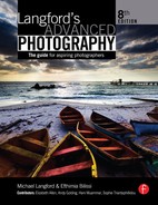
Figure 10.2 Negative/positive colour reproduction. 1: Original image exposed in camera. 2: After colour development the colour negative film carries black silver plus yellow, magenta or cyan coupled dye where emulsion layers have responded to image colours. 3: After bleaching and fixing away black silver. 4: The resulting colour negative. Note that the negative mask is omitted for clarity.
If all this sounds complicated, it is far less demanding than the older K-14 Kodachrome process. Kodachrome had no couplers built in, so each emulsion layer had to be separately fogged and cyan, magenta and yellow colours developed separately.
Colour negatives
The processing of colour negative films with the C-41 process starts with colour development, which is the most critical stage (Figure 10.2). Next the metallic silver is removed by bleaching and fixed. Finally the film is washed and stabilized. During development (and subsequent silver removal and stabilization) fine changes also occur to the integral colour masks. Properly carried out, this should give a colour negative matched in contrast range and different absorptions of red, green and blue light to ‘ft’ the characteristics of the same maker’s negative/positive colour printing paper. Departures from normal, such as lack of correct temperature, agitation and timing control, produce problems at the printing stage. Such negatives are mismatched to the paper and they may have crossed curves (Figure 10.3). No one set of filters can correct this during enlarging. Absolute consistency of film processing is therefore important.

Figure 10.3 Inaccurate processing can produce ‘crossed curves’ in the response of colour reversal (top) and colour negative film (bottom). The slide here will have a magenta cast to shadows and cyan cast to highlights. Colour prints from the negative will show an increasingly greenish cast in darker tones when correctly filtered for palest parts of the picture.
Chromogenic (dye image) monochrome negatives
Chromogenic monochrome negative films produce black and white images with the convenience of C-41 instead of black and white processing because they contain couplers in their several emulsion layers. Resulting images have a warm, brownish black – the combined dye layers give a rich tone scale and allow good exposure latitude. Chromogenic monochrome negative films are optimized for printing on black and white paper (e.g. Ilford XP2 Super) or colour negative paper (e.g. Kodak BW400CN).
Cross-processing of films
Treating films in a processing sequence designed for another film type gives a variety of results, depending on the brand and the particular film you used (Figure 10.4).

Figure 10.4 What happens when you put film through the wrong process. ‘Regular’ black and white means silver image films, not dye image types designed for C-41. (Some of these may differ in detail according to brand and types of film.)
Sometimes you may use the wrong combination by error or you may carry out intentional cross-processing to produce unusual colour images for illustration purposes, especially in the flashion and music business. Similar results are possible by digital manipulation – without risk to any of your original shots.
If you want to create images by cross-processing of films it is always better to shoot generously, setting different ISO speed ratings, and then ask the lab to give your films clip tests before deciding the best development time. Not all labs offer cross-processing, as this holds up other work. There is also a limitation on how many films can be cross-processed in a lab, for example colour negative films processed in E-6, without having an adverse effect on the E-6 process.
Black and white prints
Fewer developers are designed for printing papers than for films, and they are all more active and fast working. Choice centres on the ‘colour’ of the black and white image it will produce. Regular, PQ-type developers (they include phenidone and hydroquinone developing agents) give neutral black images on both fibre-based and resin-coated (RC) bromide papers. RC papers develop much faster than fibre-based papers because of developing agents already incorporated into the emulsion, which hasten the start of visible image formation. The non-absorbing base of RC papers also minimizes carry-over of chemicals so that further stages – especially final washing – are much shorter compared to the fibre-based papers. Other ‘restrained’ type developers for chlorobromide emulsion papers give results ranging from cold black to rich brown, according to formula.
Generally, you should keep print-development times constant. Too little development gives grey shadows and weak darker tone values, too much begins to yellow the paper base and highlights due to chemical fog. After development, stop bath and acid hardening fixer can be the same formula as the films, although the fixer is used at greater dilution.
Prints and display transparencies from colour negatives and slides
The two-solution RA-4 process used for negative/positive print materials is like a truncated form of colour negative film processing. All colour printing papers have an RC base. During the critical first stage the colour developer produces black silver in exposed emulsion layers and by-products which react with different couplers in each layer to give cyan, magenta and yellow image dyes (see Figure 10.5). This is followed by a bleach/fix stage to convert the silver into soluble compounds you remove in a final wash.
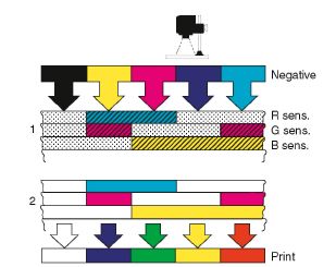
Figure 10.5 1: Negative exposed on to colour paper, which is then colour developed. Black silver and a coupled dye form according to each emulsion response to exposure. 2: After bleaching and fixing. Seen against its white base, dye layers reproduce colours of the original camera image.
As in C-41 processing, there is no fexibility in timing and temperature control is critical. It is very important that processing gives print-to-print consistency. Variations create images with colour shifts, poor tone range and stains. They can totally confuse your attempts to control results on the enlarger through filtration and exposure. Also note that colour printing materials may be suitable for printing with both analogue and digital enlargers, but usually they are optimized for one of the two methods.
Printing from slides can be carried out using Ilfochrome paper, which requires dye-bleach processing. Ilfochrome material has fully formed cyan, magenta and yellow dye layers already present in the red-, green-and blue-responsive emulsion layers. The first stage of the P3 process (P3 X for roller transport processors – see page 283) is dye-bleach. Dye-bleach processing uses, as a first step, a black and white developer to form a negative black silver image in each emulsion layer according to its response to light. The second chemical step is a bleach which removes the silver and the dye where silver is present. At the next stage the by-products of bleaching are made soluble by fixing and finally removed by washing. The remaining unbleached dyes leave you with a positive colour image matching your slide (Figure 10.6).
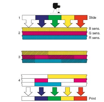
Figure 10.6 Positive/positive colour reproduction with dye-bleach paper. 1: Slide, projected byenlarger. 2: Simplifed layers, already containing dye with silver halides, exposing to image. 3: After development, black silver negative images form in each layer according to emulsion response. 4: After silver/dye bleaching. Dyes remain only in areas unaffected by development. The print reproduces the colours and tones of the original slide.
You can print colour display transparencies from digital images or colour negatives by using film-based material which is handled and exposed like sheets of negative/positive paper. The same colourprint chemicals are used (RA-4 method) but stages need different timings. This is an effective way to make large-scale transparencies for lightbox display in exhibitions. Display transparencies from digital images and slides can be printed with Ilfochrome materials, which are available in clear and translucent polyester films. They are processed with roller transport processors using the P3 X processing as for Ilfochrome paper.
Points to watch
Whatever process you intend to carry out, the key aspects to organize properly are: temperature, timing, agitation, physical handling without damage and the condition of the chemicals.
Temperature
Temperature must be tightly controlled if you expect to handle critical processes with any consistency. Large volumes of each solution hold their temperature longer than small ones. Small quantities can be brought to the correct temperature quickly but equally they soon change again if poured into a tank or through which is colder or warmer. They can also be affected faster by changes of the ambient room temperature.
The temperature of the solutions can be controlled and kept constant with water jackets. The tanks with the solutions are immersed in the water jacket and their temperature is controlled by controlling the temperature of the water.
Colour materials have less tolerance to temperature changes of the processing solutions compared to black and white materials. Any deviations in temperature during processing affects the rates of development in different emulsion layers, so you may get a faulty colour balance.
When you hand-process black and white film, however, and you have to use a temperature other than that which has been specified, you can alter the processing time to compensate for the change in temperature. You can find the processing time that corresponds to the temperature you are using for your particular developer and film in time/temperature tables or graphs (Figure 10.7). You should not exceed the upper and lower limits of development time and temperature because the processing characteristics will change beyond these limits.

Figure 10.7 Time-temperature graph for a black and white developer which gives correct density and contrast when used for 41.2 min at 20°C. Between 16 and 24°C, temperature changes can be largely compensated for by altering time.
Timing
Accurate timing is as important as accurate temperature. Times given for each step when you hand-process include a 10-second drain period for films (20 seconds for prints) to avoid carry-over of chemical into the next solution. Timings are usually different when you process by machine, depending on how the film is agitated in your type of equipment. You must keep tight control of timing when processing colour negatives at all stages. In colour slide processing increases or reductions in the timing of the black and white development (not colour development) stage push or hold back films to compensate for under- or overexposure, similar to black and white processing. Similarly the degree of development alters the contrast of your result. Note, however, that you must not alter the times for the other processing stages. Remember that the range of adjustments open to you is much more limited compared to black and white film. Beyond a certain point the image looks ‘wrong’, with coarser or flatter colours, pale shadows and a tendency to take on a colour cast which differs according to brand type.
Agitation
Agitation is an important part of processing, especially at the development stage because it affects the degree of development. If the agitation is too little then the development is uneven across the film and there is insufficient density in the negative highlights. By-products diffuse from emulsions too slowly, forming streamers. Over-agitation also allows more firesh developer to reach the emulsion than is intended for the process, giving extra highlight density. In colour films it disturbs the way by-products are produced in emulsion layers, giving excessive dye formation. It may also create uneven ‘fow marks’, particularly in films carrying perforations. In automatic processors agitation takes place through movement of the material (see page 282), but some automatic processing machines or deep tank lines have systems that provide controlled agitation with solution recirculation or gaseous-burst agitation. When you carry out hand-processing of films or paper you must follow precisely the agitation instructions provided by the manufacturer of your processing solution for consistent results.
Physical handling
Physical handling of the materials, if it is not carried out carefully, may cause them damage during processing and this is most critical when processing films. The gelatin of photographic materials is thin and designed to absorb liquids. Before processing you must therefore be careful to avoid any splashes on the unprocessed film or handling it with damp hands. Careful loading of the film in the reel is essential to avoid any contact of the film with the side of the tank during agitation. You must also ensure that the reel and tank are dry before loading the film.
When the material is being processed and is wet and swollen, it is especially delicate. Good maintenance of the rollers in roller transport machines is important to avoid any problems. Otherwise chemical by-products, fakes of gelatin, scale or grit build up on rollers and damage everything you put through. You must also check whether the water you use for diluting chemicals or washing the film (or paper) has any debris. The debris will remain and dry on the emulsion, and any attempts to remove it will result in scratching the material. The same applies if there is dust in the air where the film or paper dries. Check if the filter of the air dryer needs changing. During that stage you must also be careful and avoid any splashes on the material when it is dry or nearly dry. Remember to drain and wash the processing and washing tanks when the processor will not be used for more than 6 weeks, to avoid build-up of algae.
Chemical solutions
Points to watch here are accurate mixing, prevention of contamination and avoiding the use of exhausted solutions. The processing chemicals are packaged in the form of powder or liquid and are ready to be added to water. Accurate mixing is very important and demands constant attention, especially when dissolving powders. Component powders or liquids mixed in the wrong order may never dissolve or may precipitate out unexpected sediment. Stirring, with a suitable chemically inert and non-absorbing mixing rod, is essential when mixing. The mixing water should be at the recommended temperature or some chemical contents may be destroyed (much higher temperature) or some components may not dissolve (much lower temperature). Observe health and safety recommendations shown on page 440. Mix in a well-ventilated place, wear gloves and do not lean over the solution you are preparing. This applies especially to bleaches and stabilizers. Always remember that you must not store chemicals or chemical solutions in areas where you store food, such as the refrigerator.
Avoid all risks of cross-contamination between solutions, especially between developers or developers and bleach/fix, when mixing or processing. Thoroughly wash mixing equipment, measures, bottles and tops, and thermometer before changing from the preparation of one chemical solution to another and never let film hangers, thermometer, etc. trail one solution across a container holding another. To be on the safe side, always mix a kit of chemicals in the same order as the process, starting from the developer. For some automatic film processors and mini-labs the processing solutions are available in cartridges, so you do not need to mix chemicals.
Solutions often start to deteriorate as soon as they are left uncovered in contact with air, as well as when used to process emulsions. This is where ‘one-shot’ processing has its main advantage. However, throwing away chemicals after every process is expensive and impractical for large-volume processing and continuous-processing machines. Developer storage tanks (or deep-processing tanks when not in use) need floating lids to minimize contact with the air. Log the total amount of material you put through one solution and try not to exceed the maximum area recommended by the manufacturers for that volume. As repeatedly used developers become weaker, you may be able to compensate by increased processing time or, better still, work a system of replenishment.
Chemicals and chemical solutions before and after mixing should be stored at temperatures between 5 and 30°C. The period for which they can be stored is given by the manufacturer.
Replenishment
Replenishment means adding chemicals to gain a longer life from repeatedly used black and white and colour developers. Bleaches and fixers can also be replenished and ‘regenerated’ but stop baths and stabilizers are relatively long-lasting and cheap, so they are usually discarded completely when used up. Each replenisher solution (or powder) is formulated for a particular developer, designed to replace those of its constituents such as developing agents most used up during processing. It also has to be strong enough to help counterbalance the by-products that film and developer create between them, which accumulate in the solution and slow up development action. Replenisher is designed to be added to the main solution in carefully measured quantities. Too much or too little will seriously alter performance instead of the main aim of keeping processing consistent, so carefully follow the instructions of the manufacturer for the specific chemicals and tanks.
Fixers and bleaches can be replenished with calculated volumes of either firesh amounts of the original chemical or specially formulated replenisher solution. The very action of fixing and bleaching causes silver salts to accumulate in these solutions. Silver can actually be reclaimed and sold and the ‘regenerated’ solution replenished and returned for use in film processing (see page 291). Eventually, of course, every processing solution, however carefully replenished, approaches a terminal state of exhaustion and must be thrown away. The whole point is to keep it working consistently for as long as possible, so that you get greatest value for money.
Equipment
Highly controlled machine processing is ideal for the least fexible, temperature-critical processes such as colour negatives and prints, and reversal colour films and prints. It also suits black and white RC prints. On the other hand, the variety of developer/ emulsion combinations you can pick from for black and white negative and fibre-based printing paper still makes hand-processing attractive. Hand-processing is also the easiest way to vary development times for individual sheets or rolls of film, as required for the zone system (page 129). Figure 10.8 compares the technical and economic features of manual and machine processing.
Processing in trays
Manual processing in open trays or troughs is still appropriate for small volumes of black and white non-panchromatic prints or sheet films. It is very fexible: you can easily check results under safe lighting during processing and use relatively small quantities of chemicals. Equipment is cheap too. However, trough or tray processing is messy, unhealthy (you breathe in chemical) and not very consistent, and solutions oxidize quickly. All colour work and any processing needing total darkness is too awkward and unpleasant to be handled this way.
Tanks and tank lines
Small roll or sheet film hand-tanks are the cheapest reliable method of processing one to three films at a time (see Langford’s Basic Photography) (Figure 10.9). The next step up is to have a run of deep tanks, each 15-litre tank (Figure 10.10) set into a temperature-controlled water or air jacket. Each tank contains a separate chemical solution, according to the process you are running, plus a rinse/wash tank. You can process individual sheet film in hangers, agitating them by hand and moving them from tank to tank in darkness. Quantities of sheet film, rollfilms in reels and printing paper can be handled the same way in purpose-made racks. A single rack will accommodate up to 20 or 30 reels of 120 or 35 mm film, or 24 sheets of 4 × 5 in. film (102 × 127mm).
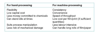
Figure 10.8 The advantages of hand-processing and machine processing.
Tank lines are fairly cheap to set up and run for any process, and allow sufficient throughput for smaller professional users. However, someone has to be present to manually handle every batch – reversal processing is especially hard work. You must take care over process control and replenishment if you want consistency (Figure 10.10).

Figure 10.9 A hand-tank used to process 35 mm film or 120 roll film.

Figure 10.10 Basic 15-litre tank sink line. Water jacket (J) encloses all tanks and is fed from thermostatic mixing valve (M), which also supplies wash tank (W). Temperature monitoring unit T has probe directly below critical developer tank (1). If temperature drops, monitor causes solenoid (S) to inject additional hot water. Nitrogen gas passes through electronic valve V regulating the frequency and duration of each burst. It then supplies flat tube distributor (D) moved from tank to tank along with rack (R) of films on hangers (H). After first stages demanding total darkness you pass the film rack through a trap to the other half of the unit, in room lighting. Here another gas/air distributor can take over.
Drum processors
The heart of a drum processor is a light-tight cylinder you load with paper (or film in a suitable adaptor). All processing stages then take place in normal light. The cylinder rotates on motor-driven rollers within a water jacket and you pour in a small quantity of processing solution through a light-trapped funnel (Figure 10.11). Within the turning drum the solution spreads rapidly and evenly over the surface of the emulsion. Drum movement backwards and forwards gives agitation; the thermostatic water jacket controls temperature. Notice how, unlike tank processing, where material is totally immersed in solution and given intermittent agitation, drum

Figure 10.11 Drum processor. Drums accept print or film (roll or 35 mm on reels) loaded in the dark. Storage containers, measured volumes of solutions in containers ready for use, and drum are all half submerged in a temperature-controlled water jacket (W). The drum couples to a motor unit through a magnetic lid. Lever (L) is used to tilt the drum at the end of each stage, discarding used solution down the drain. The next chemical is then poured into funnel (F) while the drum continues to rotate.
processors give intermittent immersion and continuous agitation. This may mean changing timings, even though solutions and temperatures remain the same.
Drum processors work on the discard principle – at the end of each step you tilt the drum, discard the used solution, then return it to the horizontal and pour in the next liquid. A few models can be programmed to work automatically, but most are labour-intensive. However, a drum processor is versatile and reliable and also the most economic way to process occasional large colour prints, although it is slow and inconvenient for large quantities of paper or film. Maximum capacity per loading ranges from four to 20 prints of 8 × 10 in. (203 × 220 mm) or 2–10 for 120 rollfilms, according to drum size.
Automatic processors
With fully automatic, programmed processors you are moving up into the big league – fnancially and in terms of throughput. The cost of equipment may be 10 times as much as a manual drum system. The main types described below are the roller transport, dip-and-dunk and continuous-strand machines, named according to the way they move the material through solutions. Most need large and therefore expensive tanks of processing chemicals which make them uneconomic to run unless you process at least 100 films or 50 prints per week. They are ideally suited to multiple-stage, rigorously controlled colour processes – you can safely leave them like washing machines and do other jobs while they are at work.
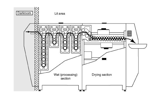
Figure 10.12 Roller transport processing machine, showing the path taken by sheets of material. This one is designed for colour paper–similar types made for films differ in their roller surface and dryer detail.
Roller transport machines
These machines contain dozens of slow-moving rollers, turning continuously to transport individual films or sheets of paper, usually up and down along a sequence of deep tanks. They may be designed to be built through the darkroom wall (Figure 10.12) and into a lit area. More often, film processors offer loading arrangements you can use in normal room lighting. Here a light-tight box at the feed end has armholes fitted with gloves through which you can open a film holder, or unseal a rollfilm and ‘post’ the exposed material direct into the machine. Either way you feed the material through dry receiving rollers in darkness and receive it back dry from the delivery end of the machine, where it has finally passed through an air-jet drying unit.
The large-volume tanks are thermostatically controlled; the rollers give continuous agitation. Roller speed is the same in all tanks – for the longest stages of processing you have tanks which are deeper or longer than tanks for short stages. You can run the whole machine slower or faster while films (or paper) to be pushed or held back are passing through the developer stage.
Roller transport machines are very convenient to use. You can feed in a mixture of sheets or lengths of film (or sheets or rolls of paper) at any time. However, each machine tends to be dedicated to a particular process. Changing to another is possible but normally means draining and changing expensive volumes of solution, which can be a major operation. Typically a 24-in. (610-mm) wide roller machine designed to process negative/positive colour prints at 200 mm per minute can turn out up to 120 prints of 8 × l0 in. every hour.
In deep-tank roller transport machines the chemicals have to be very carefully replenished, usually by automatic injection.
Dip-and-dunk film processors
Also known as ‘rack and carriage’ or ‘rack and tank’ processors, these are effectively a robot form of deep-tank hand line. As Figure 10.13 shows, the machine stands in the darkroom and

Figure 10.13 Dip-and-dunkfilm processor. The machine stands entirely in the darkroom –the gantry contains an elevator (shown in action, right). Pumps circulate each chemical. A drying cabinet, nearest end, accumulates finished work.
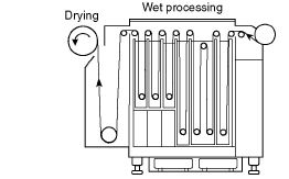
Figure 10.14 Continuous-strand processor, working from a bulk reel of exposed film.
films are suspended from hangers on a motorized lift/ carriage unit over a series of tanks. The machine lowers hangers into solution, gradually inches them along the full length of the first tank, then lifits and lowers them into the next solution. The longest stages have the longest tanks, and the solutions are thermostatically heated and pump-circulated. Films on their hangers finally pass along a drying compartment. There is no risk of damage from poorly maintained rollers with a dip-and-dunk processor. Mechanically, the equipment is fairly simple but requires a lot of space (with good headroom) and large volumes of solutions.
Machines are also dedicated to particular processes. You can put through material of mixed sizes at any time by attaching a rack of films to the transport mechanism at the start point of the process. Output ranges from about 40 to 100 rollfilms (120) per hour, according to the size of the machine.
Continuous-strand processors
Machines of this type are designed for processing long lengths of film (aero-survey or movie films, for example) or paper (output from roll paper printers). They work like roller transport deep-tank units but only have rollers at the top and bottom of each tank (see Figure 10.14). To start up, you must thread the machine with a leader and then attach to the end of this the material you want to process. Other lengths of the same width are attached in turn to the end of previous material, forming one or more continuous strands passing through the machine at constant speed and rolling up dry at the other end. When used for prints, really accurate instrument control of image exposure and light filtration is essential, for it is not very practical to put through test exposures.
Agitation takes place through movement of the material you are processing through the tanks, but some processors inject gas-burst agitation into key solutions as well. Each machine is dedicated to a particular process. Solutions are continually replenished and recirculated through filter and heater units by pumps. A large paper-processing machine of this kind can produce about 500 8 × 10 in. colour prints per hour.
Mini-labs, hybrid systems and dry mini-labs
So called ‘mini-labs’ are typically paired, firee-standing, units intended for photographic retail stores – they are able to provide colour negative film processing and printing to one or more fixed sizes on a semi-automatic basis. High-end machines can be very expensive, and contain negative scanning systems which allow monitor screen previews of print results given automatically programmed colour correction, local shading, etc. Prints are exposed on to roll paper.
Hybrid roll paper mini-lab systems (or digital mini-labs) which can print images from films (colour negatives and slides) and digital files are now the most common. When printing from films, they first scan each frame, and then pass the digital file through an image-processing station where computer software automatically makes corrections to density, contrast and colour balance, displaying changes on a monitor screen. Then this image data is transferred to an output section – a printer containing a laser exposure system with red, green and blue lasers. The light sources are moderated by the digital image information as they scan as a combined focused spot of light over the surface of a roll of silver halide negative/positive colour paper. Finally, the exposed paper goes through a conventional RA-4 chemistry roller processor. The prints can have dimensions up to 305 × 457mm. There are also mini-labs that print up to 210 × 914mm, depending on the aspect ratio of the image. Other options such as ID photo printing, multiple photos, etc. are also available.
Some of these systems can also be connected directly to a digital camera (or PDAs and mobile phones via a USB port or Bluetooth) to download the digital images or they read image files from storage media such as CD-ROMs, DVDs, memory cards, etc.
Direct conversion from digital to silver halide image is now an important way of printing large-size high-resolution colour prints. Several digital printers (e.g. Durst ‘Lambda’) are designed to function direct from any suitable digital image data. Like the mini-lab printer described above, a light-tight unit houses R, G and B lasers moderated by the disk’s R, G and B digital signals. The three sources merge into a spot of light which moves backwards and forwards across the surface of a wide roll of colour paper or display film. Total exposure time depends upon the output resolution you have set, as well as size.
The advantage of these direct digital printers, especially for murals, is that huge darkrooms and horizontal enlargers become unnecessary, and provided your digital file contains sufficient data the image resolution is excellent since the (overlapping) scan lines reveal no pattern, and total absence of enlarger optics eliminates hazards like resolution fall-off at the corners of your image. The picture can be instantly changed in size, as can the type of wide-roll silver halide print material the unit has been loaded with – colour or black and white, on paper or display film base.
Thanks to all this ‘hybrid’ work there are labs that can still run RA-4, C-41 and E-6 chemical processing machines alongside their new digital electronic systems. Additional non-silver halide activities come within the lab’s orbit too – computerized image manipulation, for example, plus printout by inkjet or dye sublimation (see Chapter 7). Many of these services demand very expensive high-end equipment, and are only fnancially viable for large custom labs and bureaux servicing professional photographers.
Dry mini-labs are a recent option for work only with digital images. The dry mini-labs employ inkjet technology (see Chapter 7) and use sheet or roll inkjet paper. They are versatile systems with a wide range of output print dimensions. They may also offer double-side printing when sheet paper is used and the option to connect a scanner.
Making a choice
There is clearly a great difference between a simple hand-tank and a fully automatic processing machine, although they can both basically run the same process. Similarly, every update in a process which can reduce the processing time (or, better still, combine solutions without loss of quality) means a substantial increase in output from the bigger machines. Before deciding on what equipment to buy (or whether to use a reliable custom laboratory instead) think hard about each of the following.
Pattern of workload
Is this steady and consistent, or varied and erratic? Do you want facilities that are fexible, or need to churn out steady quantities using one process only? How important is speed? Would it be best to buy something that has greater capacity than your immediate needs, with an eye on the future? (Perhaps you could also do some processing for other photographers in the first instance.) Should you consider buying a digital printer or digital mini-lab?
Cost
This is not just the capital cost of the equipment but the often high-priced chemicals it uses, plus servicing and spares. Cheapest outlay is on labour-intensive facilities like a hand-tank line, but this will take up a lot of your time. Paying someone else to work it could prove more expensive than an automatic machine.
Installation
Do you have enough darkroom space, suitable water supplies, sufficient ventilation – especially where dye-bleach processing will take place? (Some chemical kits include a neutralizer that you mix with discarded bleach before disposal.) Will the floor stand the weight? Large tanks of chemical or wash water are very heavy. Is the ceiling high enough? Apart from dip-and-dunk needs, large roller processors must have sufficient headroom to enable you to pull out racks vertically for cleaning. Perhaps you should consider a mini-lab as the most compact and self-contained kind of machine for large volumes of small prints?
Troubleshooting
Are you the type to conscientiously maintain good batch-to-batch quality on the kind of equipment you intend to have? For example, it may be best to choose some form of one-shot processing if you are likely to forget to replenish. Are you prepared to wash out racks of rollers thoroughly or trolley-in a heavy cylinder of nitrogen? Above all, if results come out with increasingly green colour casts or some other unexpected effect, will you wish you had used a laboratory or do you have enough persistence and interest to track down the cause and correct it? This is where some form of process monitoring will let you know what is going on. Monitoring can reveal subtle changes before they start to noticeably damage your results and become difficult to rectify.
Process control
The best way to monitor the total effect of your processing system solution condition -temperature, timing, agitation and general handling - is to put through some exposed film. Then by comparing your results against some of the same film processed under ideal conditions, variations can be measured. To do this job properly, you need the following items:
1. An exposed test piece of film or paper to process, plus another identically exposed to the same image and known to be correctly processed.
2. A densitometer - an instrument to make accurate readings of results.
3. The monitoring manual or software package issued by the film/ processing kit manufacturer to diagnose likely causes of any differences between your results and the reference film.
None of this is cheap, but it is a form of insurance which becomes more valid the larger the scale of your processing. However, there are also some shortcuts, as you will see shortly.
Process-control strips
These are strips of film or paper a few inches long exposed by the film manufacturer under strictly controlled conditions and supplied ready for processing in boxes of 10 or 20 or so. Different strips are made for each black and white and colour process in which process control is normally practised. Each strip has been exposed to a scale of light values (Figure 10.15). Colour strips also contain some coloured patches and (sometimes) a head and shoulders colour portrait image. One strip in each box has been processed by the manufacturer under ideal laboratory conditions to act as a comparative standard. Each reference strip and control strip have a code number that indicates the batch of film (or paper) that was used. The manufacturer provides correction numbers for the specific batch. Follow the manufacturer’s instructions when you change to a new batch of strips.
Unprocessed control strips are best stored in a freezer at -18°C or lower so that changes in the latent image cannot occur. Allow them time, around 15 min, to return to room temperature before use (the same applies for the reference strip - if it has not reached room temperature the density readings will be wrong). The idea is that one control strip is processed at regular intervals (once a day, once a week, or even with every batch of film, according to your pattern and volume of processing) alongside the batch of film you are processing, then checked against the manufacturer’s reference strip. Unprocessed control strips must be handled by the edges to avoid any damage on the emulsion or fingerprints. Store the reference strip in its envelope. You will avoid colour fading of the strip due to unnecessary exposure to light.

Figure 10.15 Processed monitor control strip for colour reversal (positive) film (left), colour negative film and negative/positive colour paper.
Reading results
After you process the test strip, you can do an initial check by viewing it side by side with the reference strip on a lightbox. This will show you any major processing errors at once (Figure 10.16). For a more thorough evaluation of the process, however, and to detect very slight drifits (especially colour) you must use an instrument known as a densitometer.
With a densitometer you can accurately make spot readings off the tone or colour patches on your process-control strip. The densitometer has a transmission illumination head for films (passes light through the film base from below) plus a refection head which refects light off print surfaces at a fixed angle. Light-sensitive cells receive the light and make a Status V reading of black and white visual density. For reversal film or colour printing papers, Status A red, green and blue responses are measured and correspond broadly to the visual effects of the cyan, magenta and yellow dye images present. Equal red, green and blue Status A readings indicate
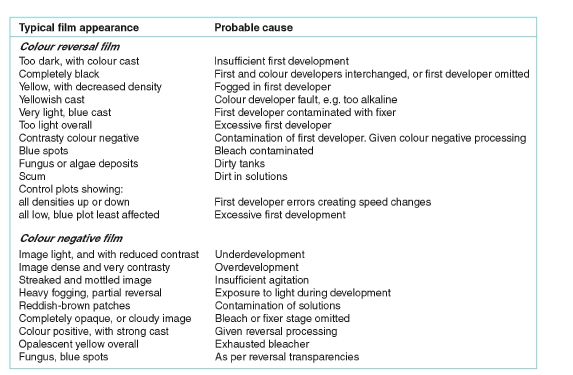
Figure 10.16 Colour film processing faults. (Some of these may differ in detail according to brand and types of film.)
a visual neutral. Red, green and blue Status M responses are measured for colour negative films and can be used to predict printing conditions necessary for consistently neutral balanced prints, as well as for quality control purposes when appropriate test strips are used. Density values appear on a readout panel.
The difference between each reading and that of the equivalent part of the reference strip is logged on a special chart (Figure 10.17). The procedure is much easier if your densitometer feeds a computer plotter with a program which places each reading you make directly on to a chart displayed on its monitor screen. Plots can then be printed out as hard copy and archived on computer disk.
Deciding what it all means
Your process-control chart is designed to make variations stand out clearly. Unless something disastrous has happened (developer contaminated with bleach/fix, for instance), plots should not vary greatly. Trends are more important than individual values. Plots which show upward trends indicate overactivity, with too much dye formation in colour materials. Downward trends usually suggest the need for replenishment. Also note that sudden changes indicate different types of problems in the processing than gradual changes.
The manufacturer’s manual or computer software for the process will reproduce similar patterns and give help and advice on action to be taken. You must check whether any of the process parameters exceed tolerance limits. In that case you have to stop the processing and determine the problem. Always make any adjustment gradual and allow it time to take effect.
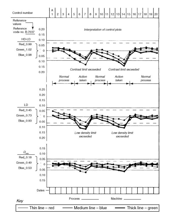
Figure 10.17 Monitoring chart for a colour negative process. Reference values for the manufacturer-processed strip appear in the left-hand column. For each strip put through with film, red, green and blue readings are made from each of high-density, low-density and Dmin steps. These are turned into density difference (top), low-density (middle) and Dmin (bottom) comparisons with reference values. Notice how the tolerance limits (shown by broken lines) become narrowest at Dmin.
If you do not want to do the process control yourself and purchase further equipment, you can subscribe to the manufacturer’s laboratory check service.
Silver recovery
Discarding chemicals in the drain pollutes the water and you can be prosecuted if you do not do something to reduce effuent silver polluting public waste treatment systems, as laid down by ecological controls. Check with your water supplier or local environmental authorities to ensure that you dispose photographic chemicals safely.
Film fixing and bleach/fix solutions gradually accumulate an appreciable quantity of soluble silver salts from the materials they have been processing. Used black and white fixer can contain up to 4 g of silver per litre. It is possible to reclaim some of this metal from fixer solution and sell it to a silver refiner. Silver recovery is an option that you should consider not only for ecological but also for fnancial reasons, depending on the quantity of photographic materials you are processing. The method of silver recovery depends on the volume of disposable chemicals, the cost of the recovery equipment, and the time and effort needed to use it.
In practice, studios and smaller labs often go for a bulk collection service. Big users, processing over 50 000 films a year, can seriously consider on-site treatment or on-site recovery, and here the two most common methods are metal exchange and electrolysis (Figure 10.18).
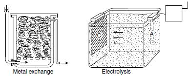
Figure 10.18 Two methods of recovering silver from a spent fixing bath. Metal exchange technique uses iron (steel wool), which is in a container where the spent fixer solution passes from and bleeds off to waste. The steel wool converts over several weeks to grey silver. In electrolysis current fows from the anode (A), plating the silver on to the cathode (C).
Colour printing equipment
Colour printing is more demanding than black and white because in addition to your skills of judging exposure, shading and printing-in, etc., you have to develop the skill of judging colour and make colour corrections. You work in different darkroom conditions, under very dim safelights or in complete darkness. The processing of the printing material is also different: you do not work with open trays and you have to keep tight control of the processing conditions. It is also important to check whether you have normal colour vision, if you find subtle colour differences difficult to detect (see page 20).
To colour print you basically need an enlarger with a lamphouse which not only evenly illuminates the film in the carrier (as in black and white) but can also be altered in colour content. Colour adjustment is vital to give you filexibility – within reason, you can match the colour balance of the film image you are printing to suit the batch of colour paper, compensate for enlarger lamp characteristics, etc. Above all, it lets you fine-tune your record or interpretation of the subject. There are two main ways of controlling illumination colour:
1. Giving one exposure using yellow, magenta or cyan filters in the light path. This is the most common method and is known as ‘subtractive’.
2. Giving three different exposures separately through blue, green and red filters. This is known as ‘additive’ printing (see Chapter 1).
Subtractive filter (‘white light’) enlarger heads
A typical colour head enlarger uses a tungsten-halogen lamp with built-in reflector. (More light is needed than given by most black and white heads, due to losses later in the filtering and light-mixing optics.) Power to the lamp should be through a voltage-stabilizing transformer which smoothes out any dips or surges of current caused by other electrical equipment nearby that would produce changes of lamp colour temperature.
Next in line come three strong yellow, magenta and cyan filters. These slide into the light beam by amounts controlled by three finger dials on the outside casing or solenoids in circuit with some electronic system such as a colour analyser (see page 303). Filters themselves are dichroic types, glass thinly coated with metallic layers which refect the unwanted parts of the spectrum and transmit the remainder, instead of filtering by dye absorption of light. This gives them a ‘narrower cut’, a more precise effect on wavelengths, avoiding the usual deficiencies of dyes. They are also more fade-resistant - important when you keep introducing part of a filter into a concentrated light beam.
The effect on printing light colour depends on how much of each filter enters the beam - a 130Y filter pushed across one-ffth of the light beam has a 26Y effect. Values are shown on finger dials or diodes, typically between 0 and 130 or 200 for each hue.
The stronger the yellow filtering you use, the more blue wavelengths are subtracted (absorbed) from the white enlarger light. Similarly, magenta filtering subtracts green and cyan subtracts red. You can watch the light changing colour as you turn the dials. Altering each control singly from zero to maximum units tints the light increasingly yellow, magenta or cyan; increasing filtration on two controls together gives red, green or blue. If you advance all three controls the light just dims because, when equal, the three filters simply form grey neutral density (Figure 10.19). There is no appreciable colour change but the exposure time becomes longer. So if during printing you make changes which bring three values into use you should ‘subtract neutral density’ by taking away the lowest value setting from each, making one of them zero, as shown in Figure 10.20.
There may also be a separate drawer or shelf within the lamphouse for fitting an additional colour printing (CP) acetate filter when the filtration you need is beyond the range of the dichroic system. This is occasionally useful for effects or when printing from early colour negatives. Colour compensating (CC) gelatin filters are placed under the lens using a filter holder. They can be used for shading or printing-in (see page 299) but note that because they are located between the lens and the paper they may introduce distortions or reduce its sharpness. Always handle the filters carefully to avoid marks, scratches or fingerprints.
The enlarger head also contains two permanent filters. One is a heat filter to subtract infrared wavelengths and avoid film overheating, the other an ultraviolet one to absorb any unwanted ultraviolet from the lamp so that it does not affect the photographic paper.

Figure 10.19 An enlarger colour head may have only three filters, but by adjusting dial-in controls you can change the light through a wide range of primary and complementary colours. Each primary colour is made by dialling in two filters at a time (shown maximum here). Never use more than two filters at once.
After passing through the filters, the part-tinted light beam is thoroughly scrambled by bouncing it around a white-lined box and passing through a diffuser, large enough to cover the largest size film carrier you will want to use. This way it reaches the film carrier perfectly, even in colour (Figure 10.21). Diffuser enlargers are preferred for colour printing because the resulting contrast matches the contrast of the colour negative and scratches on the film are less noticeable (light is scattered less by the film scratches when a diffuser enlarger is used compared to a condenser enlarger). Most enlargers use interchangeable colour or black and white heads. You can even use a colour head for black and white printing. Dial out all colour filtration, or use the yellow and magenta filters to control variable contrast monochrome paper, following the manufacturer’s instructions (see table in Appendix A).

Figure 10.20 Eliminating neutral density. Top: colour head settings here are utilizing all three filters. Bottom: to avoid unnecessary neutral density the lowest setting has been subtracted from all three controls. Colour remains the same but light is brighter.
The remainder of the enlarger – column, movements, timer, masking frame – are basically the same as for black and white printing (see Langford’s Basic Photography). Some enlarger baseboards can have a roller paper easel attached in place of the regular masking frame.
Enlarger lens
The quality of the enlarger lens is very important because chromatic and/or spherical aberrations caused by low-quality lenses will affect the sharpness of the printed image and may also cause distortions (see Chapter 3). Always fit the best enlarger lens you can afford, preferably one of at least four elements. All modern enlarging lenses are corrected for colour, and there are also apochromatic lenses (APO) with corrected axial chromatic aberration for the red, green and blue wavelengths (see page 58). You choose the focal length of the lens according to the format of the film. For a 35 mm negative or slide use 50 mm lens, for medium-format film use 80 mm and for large format, 4 × 5 in., use a 150 mm lens. It often helps to buy a lens with a wider maximum aperture than for black and white work. This makes the focusing of masked negatives easier to see and more critical. However, always aim to expose with your lens stopped down to about the middle of its f-range for best performance.

Figure 10.21 Side viewofa dial-in head. This shows the mechanical arrangement for raising and lowering the filters into the light beam when finger dials (protruding from lamphead, left) are turned. Matt white light-mixing box (M) scatters and directs light down through a diffuser (D) to evenly illuminate negative held in a carrier below.
Additive heads
A few enlargers and printers do not use a variable-strength filtering system. Instead they have deep red, green and blue filters, one fixed over each of three lamps or flash tubes or rigged on a moving carrier which positions one filter after the other across the light beam. Every print is given three exposures, and by varying the times for each colour (with flash the number and strength of flashes) you control the effective colour of the light. Additive printing can therefore be said to expose each of the red-, green- and blue-sensitive emulsion layers of the colour paper separately. It is a system which still suits some automatic or electronically controlled equipment, as all adjustments can be made by timing. Again, it is a low-cost way of using a black and white enlarger. However, with a sequence of three exposures, shading and printing-in become difficult.
The subtractive method, however, is the one that is mainly used in photography for colour printing and this is described later in this chapter.
Print materials
Colour print materials are of three main types: chromogenic negative/positive (‘C’ type) material such as Ektacolor or Fujicolor, designed for printing from digital images and negatives; chromogenic positive/positive, reversal (‘R’ type) material; and dye-bleach positive/positive material such as Ilfochrome.
Both the second and third types are for printing from slides or larger format transparencies, with the second method not being used much any more. Each material needs completely different processing. Most printing papers come in a selection of surface finishes – typically glossy, lustre or semi-matt. Although there is no range of contrast grades as such, some papers intended for direct commercial and advertising uses are made with slightly higher contrast than ‘medium’ contrast papers for portraiture and pictures for newsprint reproduction.
All colour printing materials have multi-layer emulsions sensitive to the three primary colours of the spectrum. However, unlike camera materials, most papers have emulsions in reverse order, with the red-sensitive cyan-forming layer on top. A slight amount of image diffusion is inevitable in the bottom layer but is more hidden if this is yellow instead of the heavier cyan. Emulsion colour sensitivities have steep, well-separated peaks corresponding to the maximum spectral transmissions of the three dyes forming the film image. Remember, printing paper does not receive light from the same wide range of subject colours as camera film – everything is already simplifed to combinations of three known dyes. In part of the spectrum (Figure 10.22) print material sensitivity can be sufficiently low to permit the use of safelights which would fog colour film.
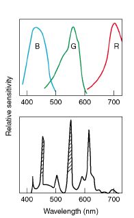
Figure 10.22 Safelighting for colour printing. Top: spectral sensitivity of the paper’s three emulsions. Bottom: spectral emission from sodium-type safelight. A filter within the unit absorbs the two shaded bands. Peak emission therefore matches the ‘gap’ between green and red paper sensitivity. However, level of brightness must remain low to avoid fogging from lower energy bands.
Characteristics of the same manufacturer’s colour negative films are taken into account in the design of negative/positive print materials. The two are to a certain extent ‘keyed’ in terms of contrast and the effects of integral colour masking used in the film. Cross-printing maker A’s negatives on maker B’s paper may need different filtration, but the result, with its mixed use of dye characteristics, may well suit your style of work. It should be noted here that nowadays colour printing paper for use in digital mini-labs is designed to produce optimal results when digital images are printed as well as images printed from colour negative film. It is available in sheets and also in roll sizes.Because of slight variations in manufacture, a few brands of colour print material are labelled with filter and exposure changes relative to other batches, like sheet colour film (see Figure 10.23). Whenever you buy a stock of paper try to ensure that it is all from the same batch. Take care over storing printing materials too.

Figure 10.23 When changing from one paper batch to another in the middle of colour printing, compare the paper labels. Differences here guide you to reset filtration and exposure time so that results remain unchanged.
Keep your stock sealed and located in a refrigerator at 10°C or less, but prevent moisture from condensing on the cold emulsion surface by allowing it time to reach room temperature before use. Exposed paper must be processed as soon as possible to ensure stability of the latent image. If this is not possible, the exposed paper should be refrigerated. Allow it to reach room temperature before you process it.
Negative/positive colour printing
The advantage of making colour prints from colour negatives rather than slides is that you get better results from a wider range of subject lighting conditions. The information encoded within a properly exposed integral-masked colour negative allows you to make greater adjustments of colour and tone during printing, without unwanted side effects such as poorer shadow or highlight quality. However, colour negatives are not easy to judge. The tinted mask and complementary image colours make colour balance impossible to assess visually except in the broadest terms, and negatives often look denser than they really are. It helps to check negatives looking through a piece of unexposed but processed colour negative film of the same brand – the start or end of a rollfilm, for example. The mask colour filters your eye and discounts the mask density present in the negative. Avoid negatives where important shadow detail is recorded as faint or non-existent. As in black and white printing, when you shade these areas the image tones they contain will print artificially flat and will also probably show a colour cast. Panchromatic film and paper should preferably be handled in total darkness. There are safelights which have filters suitable for different types of panchromatic material but even these are not absolutely ‘safe’. Panchromatic film and paper should therefore not be exposed to safelight for extended times (try not to expose the photographic paper to safelight for longer than 1 minute). Safelight filters have to be tested regularly because they fade with time and they allow a larger part of the spectrum to pass through.
Practical procedure
To contact print your negatives, proceed as for black and white, projecting an even patch of light on the enlarger baseboard and fitting your strips of film into holding grooves under the glass of a contact printing frame. Stop down the enlarger lens aperture two to three stops. If you are printing these colour negatives for the first time, without any analysing aid or previous notes, set the yellow and magenta filters according to the paper manufacturer’s recommendation. If you do not have this information try setting 40Y 30M. (Cyan filtration is rarely used in negative/positive printing, except for effects.) Lay a half sheet of paper under part of the set of negatives representative of the whole and give a series of doubling exposure times roughly based on what you would give for black and white paper. Note down filtration and exposure in a notebook or on the back of the sheet. When your test is processed, judge it under your viewing light. Make sure that the paper is dry when making judgements (the colours and density of a wet print change significantly when it dries). If it is out on exposure you may have to test again, but get the density as correct as possible (at least to suit the majority of negatives on the sheet) before you go on to assess colour.
Visual colour assessment is quite a challenging task at first. The rule is: to reduce a colour cast, you reduce complementary colour filtration. So you must always remember the ‘double-triangle’ diagram (Figure 10.24), which relates primary and secondary colours. If your test looks too green, for example, reduce the magenta filtration. This turns your enlarger light greener, which makes the negative/positive colour paper give a more magenta print. So what was originally 40Y 30M might be changed by 10M to 40Y 20M for a moderate change of colour. A 05 unit difference of filtration gives a just perceptible alteration; use 20 or more for bigger steps.

Figure 10.24 Colour relationships (of light). Complementary colours are shown opposite their primaries – cyan opposite red, for example. Any one colour can be made by adding equal amounts of the two colours either side of it.
If there is not enough filtration already present for you to reduce further, then add filters matching the print cast. For example, a test filtered 00Y 40M 00C may look about 10 units too blue. You cannot reduce enlarger settings by 10Y, so change the settings to 00Y 50M 10C to increase blue (cyan + magenta) instead. With each change of filtration check out from the manufacturer’s data whether you also have to compensate exposure.
Once you have a good set of contact prints you can choose which shot you are going to enlarge, and set up this negative in the enlarger. Filtration is likely to remain the same as for the contact print version, but retest for colour as well as for exposure. Similarly to black and white printing, use paper of the same thickness as your photographic paper on the easel when you are focusing the image, and a focusing magnifier (or ‘grain magnifier’) for accuracy. Remember to open fully the lens aperture and to remove the colour filters from the light path when focusing, for a brighter image. After focusing, stop down the lens, add the colour filters and start with a series of double exposure times. As with contact sheet printing, make tests first for correct exposure and then for colour.
Use a masking frame with several segments (Figure 10.25), which allows you to cover the paper and expose each time one part of it. To determine the correct exposure more accurately, expose the same part of the image by repositioning the masking frame. Exposure time should be kept within 5–30 seconds, otherwise colour shifts may occur due to reciprocity failure (see page 301). If the print needs shorter or longer exposure times, alter the lens aperture.
Process the test print and judge exposure and colour under standard viewing light. Exposure and colour corrections are carried out in the same way as for the contact print.
Positive/positive colour printing
When you print images from positive film it is easier to judge for colour balance. You must remember that by increasing the exposure the print becomes lighter instead of darker. When you shade areas they become darker. Transparency film has no integral masking, and its contrast is greater than a negative because it is designed to look good as an end in itself rather than suit colour paper. Both these features limit your print quality.

Figure 10.25 (a) Four hinged flaps of opaque card (white on top) so only one-quarter of the paper (P) is exposed at one time. (b) You can also test exposure by covering part of the paper. Times here, top to bottom, are 15, 12, 9, 6, 3 seconds. Image © Andrew Schonfielder.
Overexposed slides are not suitable for printing because all the detail in the highlights is lost. Choose slides which have medium or low contrast. Also, you may prefer to print slides slightly underexposed because the highlights will have detail and can lighten the image in printing. Make sure your film is spotlessly clean. Any debris on the slide prints as black, which is much more difficult to spot-out than the white specks this would produce on negative/positive prints.
Practical procedure
Set up your film in the enlarger, focus the image, stop down the lens and initially set the filtration as recommended by the paper manufacturer for your brand of slide. Test first for correct exposure, then for colour as in negative/positive printing. Vary each band of exposure by about 50% around what you estimate (or measure) to be correct. Try to keep exposure time within 5–30 seconds (see page 301).
Process your material and examine dry results under your standard viewing light to judge density and colour. Remember that the darkest segment has had least exposure. Isolate your best exposure result and compare colour with your transparency. If the test looks, say, too yellow, reduce your yellow filtration. If it looks too green, reduce yellow and cyan equally – but if one of these is down to 00 filtration already you can add magenta instead. Avoid having a neutral density situation through using all three filter colours (page 292). Filtration changes of 10 units have a barely discernible effect. Expect to alter 20 units at a time, or 30–40 for more effect – all bigger steps than you normally need in negative/positive colour printing. Get used to making notes of filter and exposure time settings on the back of prints or in a notebook. Having reset your filtration, check whether the changes will necessitate any adjustments to exposure. Calculate this from the manufacturer’s table or read it with an analyser.
Shading and printing-in (or dodging and burning-in)
In negative/positive printing, shade or print-in chosen areas which otherwise print too dark or light, using the same technique as for black and white printing. Sometimes, however, pale neutral areas of your picture tend to pick up too much colour when darkened by extra exposure. This is where it helps to have a selection of gelatin CC filters to use between lens and paper (do not use CP acetate – this upsets definition when used between lens and paper). If the part you are printing-in tends to pick up, say, yellow, then print-in through a hole in a card covered by a pale yellow filter such as a CC 10Y. Alternatively, add equivalent extra yellow units to your filter head just while you give this extra exposure. Again, when shading a shadow area which has an unwanted greenish tinge, use a green CC filter, such as a 30G (or 30Y 1 30C), as your dodger. If this filter is too strong, use it for part of your shading and change to an opaque dodger the rest of the time. If negatives are too contrasty or too flat to print well, pick a paper of lower or higher contrast if available, or try cross-printing on another manufacturer’s paper. Alternatively, add a weak black and white mask to reduce or increase contrast.
In positive/positive printing you shade pale parts to make them darker and give heavy areas more exposure to lighten them. You can make local colour corrections by shading with filters. For example, if part of an outdoor shot includes shadow excessively blue-tinted by blue sky, shade this area with a CC 10Y filter.
If prints show excessively harsh contrast you may have to lower the contrast of your slide by masking it with a faint black and white contact-printed negative. As a quicker solution (although more limited in effect) try ‘flashing’ the paper after exposure. Remove the film from the enlarger, cover the lens with an ND2.0 filter and repeat your exposure time. With dye-bleach materials you may reduce image contrast by developer dilution, but this is likely to make highlights, including whites, darker.
Making a ring-around
Aset of differently filtered versions of the same picture made on your equipment forms a visual aid for judging filter changes. This is especially useful since you are working in ‘negative colours’. Pick an evenly lit, accurately exposed negative of an easily identifable subject. It must have been shot on the correct stock for the lighting (unless you habitually use some other combination) and should include some area of neutral tone or pale colour. Make one print with correct colour and density, then change filtration by steps of 10, 20 and 30 units in six directions in turn – blue, cyan, green, yellow, red and magenta (see Figure 10.26). A chart is also provided in Appendix G. Remember to correct exposures as necessary so that all prints match in density.
For positive/positive printing pick a slide which includes some pastel hues and grey or white. Make the best possible correctly exposed and filtered small print first, then increase filtration (or reduce complementary colour filtration) by steps of, say, 20 or 30 units and make other small prints with casts progressively in the directions magenta, blue, cyan, green, yellow and red.
Caption each print with the difference in filtration between it and the correct colour version. (The visual colour change this difference produces remains a constant guide, no matter what

Figure 10.26 A ring-around chart for negative/positive colour printing. Filtration data shows what to subtract from present filter settings if a print showing this cast is to revert to correct colour (centre of chart). Extreme colour shifts of 80 are included here to clarify the differences between the six colours – particularly between red and magenta, and between blue and cyan. Exposure times have been adjusted where necessary to compensate for filter change effects on density. This page is a guide to the direction and intensity of colour shifts, but for greater accuracy make your own chart using actual colour prints. In the illustrated ring-around, the filtration for the image in the centre was Y 5 53, M 5 6, C 5 0 (exposure: f/5.6, 8 seconds). Some examples of filtration in this ring-around. Image 40Y: Y 5 93, M 5 6, C 5 0. Image 20M: Y 5 53, M 5 26, C 5 0. Image 40C: Y 5 53, M 5 6, C 5 80. (Images printed with a Durst Pictochrom Diffuser Enlarger with a Schneider 50 mm f/2.8 lens.) Reproductions here can only approximate print results. Images and ring-around by Andrew Schonfielder.
negative (or slide) you print.) You must obviously process all prints with great consistency, preferably as one batch. Mount up results logically in chart form and keep them in your print-viewing area.
Use your ring-around by comparing any correctly exposed but off-colour test print from another film against the chart to decide which print most closely matches it in colour cast. Then read from the caption how much to remove from the test print filtration to get a correct print. Remember to avoid neutral density (page 292) and adjust exposure as necessary for the changed filtering. Sometimes your test will fall between two of the ring-around ‘spokes’, in which case estimate a combination of the two captions and subtract this from your filtration instead. For example, if test filtration of 40Y 40M matches a chart cast captioned 10Y, change to 30Y 40M, but if it looks somewhere between 10M and 10R (which is 10Y 1 10M), subtract 10Y 20M, resulting in 30Y 20M.
Additional points to watch
If you are only used to black and white there are two further aspects you must remember when subtractively printing all types of colour print material (negative/positive and positive/ positive). One is concerned with batch-to-batch variations and the other with reciprocity failure.
Changing batches
Occasionally, in the middle of colour printing, you finish one box of paper and have to start another which you find is of a different batch with different ‘white light’ filter and/or exposure recommendations printed on the label. The rule with filtration is (1) subtract the filter values on the old package from your enlarger head settings. Then (2) add the values on the new package to the enlarger (see Figure 10.23). Where the new pack shows a different exposure factor, divide the new exposure factor by the old one and multiply your previous exposure time by the result.
Exposure time and reciprocity failure
All colour printing materials suffer from low-intensity reciprocity failure (i.e. greatly reduced image brightness cannot be fully compensated for by extending exposure time). Emulsions become effectively slower with the long exposures for stopped-down images from dense negatives or slides, or at great enlargement ratios. For example, a ×4 enlargement at f/11 may need 7 seconds. When you raise the enlarger four times as high for a ×16 result the calculated or light-measured exposure becomes 112 seconds. However, at this long exposure the print appears underexposed, and if you further increase the time, results become correct density but show changes in colour balance and contrast due to different responses in each emulsion layer.
The best way to avoid trouble is to aim to keep all exposure times within about 5–30 seconds by altering the lens aperture whenever possible. Colour enlargers designed for large prints therefore need to have powerful light sources. They may have a diaphragm near the lamp so you can easily dim the illumination for smaller prints without changing colour content. You will also find some negative/positive papers with reciprocity characteristics specially designed to give best performance with long exposures, i.e. big prints.
Colour/exposure analysing aids
The less filter calculation and guesswork you have to do, the faster you get to a good colour print. There is a choice of several analysing aids, from viewing filters to expensive colour video. All the devices described below are designed for negative/positive printing, and most also work for positive/positive printing.
Viewing filters
If you view a faulty test print through a filter of appropriate colour and strength you can tell the best change to make to enlarger filtration. Look through CP acetates, as used for filter drawer enlargers, or buy sets of similar filters (Figure 10.27) in cardboard mounts. Have the print under your standard viewing light and hold the filter about midway between print and eye. Do not let it tint everything you see and do not stare at the print through it for more than a few seconds at a time – keep flicking it across and back. Viewing too long allows your eye to start adapting to the colour (see page 18).

Figure 10.27 Colour print viewing filters. You need a set of six of these triple filter cards. Each card has filters which are the same colour but differ in strength. Pick the filter which best corrects your test print cast.
If your test print is too ‘warm’ in colour, try looking through blue, green or cyan filters; for ‘cold’ prints, try yellow, magenta or red. As with colour transparencies, viewing through a filter tints the appearance of highlights far more than shadows. So only judge appearance changes to your print’s lighter middle tones. Having found which viewing filter makes these tones look normal, read off the required enlarger filter changes printed on its cardboard mount. (Negative/positive colour printing changes appear one side and positive/positive changes on the other.) Alternatively, if you are viewing through CP filters and printing negative/positive the rule is: remove from the enlarger filtration the same colour but half the strength of your viewing filter. For example, if a test print with a green cast shows corrected midtones viewed through a 20M filter, remove 10M from the enlarger. If this is impossible, add 10Y + 10C.
Electronic analysers
There are a great number of electronic analysers available. All make tricolour measurements of your negative or slide and read out the most likely filter for your enlarger and paper batch. They also measure exposure. Most analysers are for ‘on-easel’ use – they have the advantage of measuring the same image light that will eventually expose the paper. Some analysers are ‘off-easel’. They work separately, like a densitometer used for process monitoring, and allow you to measure your film images outside the darkroom before printing. One skilled user can therefore serve a number of enlargers.
Off-easel analysers have to be programmed for the characteristics of the particular enlarger through which your film will be printed. Then they compare readings of each negative against a memorized standard negative for which correct filtration and exposure are known. This kind of equipment best suits large laboratories employing many staff and turning out volume work.
Self-correcting systems
Several professional colour enlargers have built-in systems for self-correcting colour filtration. To begin with, the lamphouse may include a ‘closed loop’ in which tricolour sensors in the lower part of the mixing box (Figure 10.28) measure the colour content of light reaching the negative. It detects whether any changes have occurred since the enlarger was set up – perhaps through a lamp change, changing to a larger format mixing box, or just the slow effects of ageing throughout the system. The information feeds back and causes small compensating adjustments to the zero position of the filters. So each time you start up the enlarger it runs through a brief light-checking program, ensuring that any filter values you use will have exactly the same effect on the image as last time.

Figure 10.28 Basic layout of a ‘closed loop’ lamphouse system. C, control unit; M, motors to adjust the zero position of filters so that lighting colour is always consistent; N, negative; S, sensor for illumination colour.
Other systems go further and set filters for you by evaluating a test print. You first have to expose an enlargement test strip, choosing a suitable mid-grey area of your film image or using a grey negative supplied. After processing and drying, the paper test strip is either clipped over a window on the side of the lamphouse or, in some systems, is placed in a special holder replacing the film carrier. Here sensors compare its greyness against a built-in reference grey patch, both being illuminated by the light of the lamphouse itself. Sensor circuitry determines what filter and exposure changes are needed to correct any difference between the two for your next print. Test analysis of this kind checks all your variables – from lamp to processing chemicals – and can be repeated more than once to finely tune results before your final print.
Video aids
Video analysers are off-easel systems which may consist basically of an inverted enlarger colour head (forming a lightbox for your film image) viewed by a special closed-circuit colour video camera with zoom macro lens. The tricolour channels of the video system must closely match the relative colour sensitivities of the three emulsion layers in photographic colour paper. Your picture appears on a colour monitor and, by turning a switch, colour negatives are presented as high-quality positive colour images. So it becomes easy to evaluate picture content, portrait expressions, etc. and you can zoom in to preview how different kinds of cropping might look.
These features alone make video a useful tool for selecting colour and black and white negatives for printing when contact prints are not available. For colour analysis, adjust filtration on the lightbox until the picture on the screen looks at its best, then transfer these settings to your enlarger. Like all off-easel systems, video analysers have to take into account your enlarger characteristics and current paper batch data, programmed in and held in a memory.
Other colour lab procedures
Colour prints from black and white negatives
By printing black and white negatives on negative/positive colour paper you can produce results which look like toned prints. The image can be one colour overall or different areas of the paper can be given different colours or made to graduate from neutral to a colour (see Figure 10.29). Sandwich your negative with a piece of unexposed, processed colour negative film. Its yellowish mask avoids the need for heavy filtration to get a neutral result, so you then have a wider range of filter options for print colouring.

Figure 10.29 Colour print from a black and white negative. The graduated coloured tones in the picture below were created by hand shading, then printing back with changes in the Y 1 M filtration. Effects are similar to selective toning but more muted and subtle. By Tim Stephens, courtesy Faber & Faber.
First, you must establish the filtration for a neutral black and white result. Make a series of exposure tests across several pieces of paper each given large (50-unit) filter changes. Then, depending on the colour and intensity of cast in your result, work back with progressively smaller changes until you reach neutrality. Now you select the image colour of your print by appropriate filtration – for example, reducing yellow or increasing cyan to get a warm tint. For a change of tint in chosen areas, shade these parts during the main exposure, then alter filtration and print them back in again. With care you can achieve quite subtle, graduated results, such as a winter landscape greeny-grey at the bottom becoming blue–grey towards the top. It is also possible to work by hand-tinting chosen areas of black and white (large-format) negatives, which then print in complementary colour.
Dupe slides from slides and transparencies
Duplicating films are in a variety of sizes, from 35 mm to sheet film. Using low-contrast 35 mm reversal duplicating colour film, you can make colour slides from other slides and transparencies. Work with a 35 mm camera and macro lens in conjunction with one of the copying devices shown in Figure 10.30. The camera’s through-the-lens (TTL) light reading takes close-up imaging into account. Some copiers contain their own light sources – either flash (suits daylight film) with modelling light for focusing and exposure metering, or a tungsten light enlarger lamphouse used upside-down. Simpler copying attachments have to be pointed towards a suitable source. They hold the slide at the far end of a tube containing optics for 1:1 imaging. Since camera and subject are firmly locked together you can hand-hold even quite slow shutter-speed exposures. No slide reproduced in these ways will quite match the sharpness and tone gradation of an original shot, so it is always better to run off a series of slides from the original subject if you know that several copies will be wanted. Nevertheless, you can definitely improve slides which have a colour cast by duplicating them through a complementary colour filter (see Figure 10.31) or scan them and correct the colour cast digitally. You can also improve on a slightly dense, underexposed slide by giving extra exposure while copying it. Copiers have other useful functions for special effects such as sandwiched slides, double exposures, etc. Duplicating film is processed in regular E-6 colour reversal film chemistry.
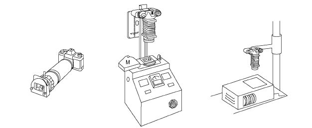
Figure 10.30 35 mm copying systems. Left: simple tube attachment incorporating 1:1 close-up lens. Centre: copier containing flash unit and modelling lamp. Right: inverted head from a colour enlarger forms a tungsten lightbox for copying. Controls here adjust colour balance.

Figure 10.31 Correction of cast by slide copying. The slide (left) was shot in fluorescent lighting and shows a characteristic green cast. In making the 1:1 copy (right), a CC 30M filter has produced correction.
SUMMARY
- Today’s mainstream chemical processes for silver halide films are black and white negative, colour reversal and colour negative types. Dominant print processes are black and white negative/positive, colour negative/ positive, colour positive/positive. Each colour process comes as a planned kit – sometimes in amateur or professional, shortened or regular versions.
- The widest choice of developers exists for black and white processing. Differences include contrast, film speed, grain and resolution. Some are designed for you to dilute and use one-shot, others have long-life performance for use in a deep tank.
- Monochrome print developers are chosen mostly for the image ‘colour’ they give, especially with chlorobromide emulsions. Fast-developing RC papers can be machine processed.
- Timing of the first stage of reversal colour film processing (black and white development) is adjustable to push or hold back film speed. Colour development times, during which couplers form dye images, should be considered infexible for colour films. Times can also be varied when developing monochrome chromogenic films.
- Cross-processing colour films gives coarsened subject hues and distorted contrast. Both can be effective for off-beat images.
- Negative/positive colour printing materials include (RC) paper and film base. Colour development is followed by bleach/fix and washing.
- For reliable processing look after temperature, timing, agitation, the state of chemicals and the way photographic material is physically handled. In all processing, be accurate and consistent.
- Prepare chemical solutions safely and according to detailed instructions. Do not risk contamination through insufficient rinsing of mixing gear, containers, etc. or sloppy working.
- Process control allows you to monitor your entire system by regularly processing pre-exposed control strips, then comparing results against a manufacturer-processed strip. You can send off for regular analysis or measure results on the spot using a computer-aided densitometer and diagnostic software.
- Ecology-based laws prohibit you from discharging silver effuent. Use a bulk collection service for spent fixer. Large labs may economically opt for on-site metal exchange treatment and/or electrolysis silver recovery. The latter allows you to regenerate your fixing solution and put it back to use.
- Subtractive, ‘white-light’ enlarger heads use different strengths of yellow, magenta and cyan filters, two (but not three) colours at a time. Additive enlargers/printers control print colour via differences in exposures through each of deep blue, green and red filters.
- Darkroom facilities beyond black and white requirements include an analyser, appropriate safelights and increased ventilation. Have a white-light viewing area for judging colour tests.
- The main types of colour print materials are chromogenic negative/positive and dye-bleach positive/positive. Colour sensitivities of each ‘set’ of emulsion layers correspond to peak transmission of the three image dyes in colour film. Similarly, print materials are keyed to the contrast and masking (if any) of the same manufacturer’s film. Store in refrigerated conditions.
- Colour negatives are difficult to assess, but working negative/positive suits wider ranging subject conditions and allows greater adjustment of colour and density. Test your print first for exposure, then for colour. Avoid negatives that are underexposed. To reduce a print cast, decrease complementary filtration; shading and printing-in follow black and white practice. When printing from slides, increasing the exposure lightens the print, and to reduce a cast, reduce filtration matching it in colour. Shading darkens and printing-in makes areas lighter. A ring-around print set forms a filtration visual aid. Always judge prints dry. Changing filtration has a stronger effect in negative/positive than the same filter shift in positive/positive printing.
- Avoid long exposure times – reciprocity failure upsets colour and contrast, although some colour papers are made specially for long exposure (large print) conditions. Where possible, widen the aperture instead.
- Viewing filters provide a simple test-print colour-analysing aid. Add to the enlarger half the strength of the filter making positive/ positive midtones look correct (complementary colour if negative/positive). Electronic analysers work ‘on-easel’ or ‘off-easel’ serving several enlargers, make integrated or spot readings of colour and exposure. They compare characteristics of film images to be printed against a standard image for which settings are known.
- Basic additive colour printing demands the simplest gear, although it is also difficult to shade or print-in. Colour is controlled by the proportion of three separate exposures through deep blue, green and red tricolour filters.
- Prints made from black and white negatives on to colour paper can be given a toned image appearance. Establish filtration for neutral black and white. Then vary colour and intensity across chosen areas by shading, changing filtration and printing-in.
- The modern colour lab handles a mixture of silver halide and digital systems.
PROJECTS
1 Make a ring-around of colour prints from black and white negatives, using the filters of a colour enlarger.
(a) Sandwich your black and white negative with a piece of unexposed processed colour negative.
(b) Make tests for correct exposure and establish the filtering that gives you a neutral result.
(c) Make one print with correct colour and density, and then change filtration by steps of 10, 20 and 30 units in six directions – blue, cyan, green, yellow, red and magenta (see chart in Appendix G). You must correct exposure when you change filtering so that all printed images have the same density.
(d) Keep a record of exposure and filtering for each print, for future reference.
2 Test both exposure and colour filtering with one sheet of colour paper. Use a device (you can also make it yourself) that has segments which allow you to expose one part of the paper each time (see Figure 10.24). The flaps should be white on top so that you can see the projected image when they are closed. Set filtration for the film type as recommended by the paper manufacturer.
(a) Lift the first fap and expose four bands for different exposure times, shading with card. Return the fap to its original position.
(b) With all flaps protecting the paper, switch on the enlarger again so that you can view the projected image on the closed flaps. You want to test exposure and filtering at the same area of the image, so you have to shift the masking frame so that the strip of image exposed when you opened the first fap now falls on the second fap. Increase or reduce filtration by appropriate units in one direction.
(c) Switch off enlarger, lift the second fap and expose four exposure bands again. Continue for the rest of the flaps. When you process the sheet you will have a series of different filtrations at four exposure levels.