
5
AVOIDING OBSTACLES
NOW YOU CAN CONTROL HOW YOUR ROBOT MOVES, AND THAT’S PRETTY COOL! BUT WOULDN’T IT BE COOLER STILL TO GET YOUR ROBOT TO CONTROL ITSELF?
You may have noticed that your little two-wheeler is quite vulnerable to all kinds of hazards while it’s running around the floor. Crashing into walls and other objects can be very annoying and even dangerous to your hardware. In this chapter, I’ll show you how to enable your robot to autonomously detect and avoid obstacles. We’ll cover the theory behind obstacle detection and how to use the sensor you’ll need.
OBSTACLE DETECTION
In order for your robot to avoid obstacles, it will first need to be able to sense them. In electronics we use specialized sensors for this purpose. There’s a variety of ways to implement obstacle detection using sensors. At the hobbyist level, there are two main approaches: digital detection and analog detection. Digital detection is excellent at sensing obstacles within a certain range, but it can’t determine the distance to that obstacle. Analog detection, on the other hand, can do both, so that’s what we’ll use here to make our robot extra intelligent.
Using Ultrasonic Sensors for Analog Object Detection
The HC-SR04 ultrasonic sensor (seen in Figure 5-1) uses ultrasonic sound to determine the distance between the sensor and an object. The sensor works in much the same way that bat and dolphin sonar works in the natural world, and submarine sonar works in the not-so-natural world.
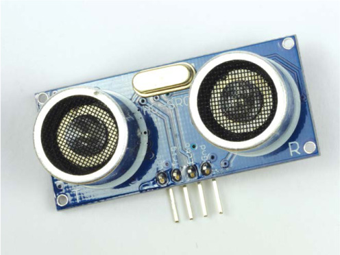
FIGURE 5-1 The HC-SR04 ultrasonic distance sensor
Sound can be modeled as a wave with varying wavelength. Only a small range of the sound spectrum is audible to the human ear. Any sound waves with a frequency above this range (20 kHz+) are ultrasound waves. Ultrasonic distance sensors are designed to sense object proximity using ultrasound reflection. A sonar system like this sends out waves that bounce off obstacles. A receiver then detects the returning sound waves. Ultrasound is accurate within short distances (around a few meters) and is inaudible to humans.
Understanding How the HC-SR04 Works
A basic ultrasonic distance sensor like the HC-SR04 is made up of a transmitter, a receiver, and some circuitry. The transmitter and the receiver are the speaker-like protrusions resembling eyes in Figure 5-1.
To determine a distance, the transmitter emits a high-frequency ultrasonic sound. This sound will bounce off any nearby solid objects and be reflected. The “bounce-back” is detected and picked up by the receiver on the HC-SR04.
Sound travels through air at a constant speed. At room temperature (20º C/68 ºF) a sound wave will travel at approximately 343 m/s (meters per second). While this is fast, it’s not instantaneous, which means there’s a small time difference between when the sound is emitted and when the bounce-back is received. Therefore, we can measure the distance by timing how long the signal takes to bounce back to the sensor.
The relationship between speed, distance, and time can be summarized as follows:
The speed of an object in meters per second is equal to the distance that object has traveled in meters divided by the time it has taken to move that far in seconds. We’ll use this equation to figure out the distance. We know the speed of sound is constant at 343 m/s, and we can measure how long the sound wave takes to bounce off an object, which is the time. If you rearrange the equation to solve for distance, you get:
This isn’t quite the full story, however. The ultrasonic pulse is emitted, bounces off an object, and is received by the HC-SR04, as shown in Figure 5-2, meaning the sound wave is actually traveling double the distance from the sensor to the object.

FIGURE 5-2 The HC-SR04 distance-measuring process
That means we need to divide the time recorded by the ultrasonic distance sensor in half, which results in the following equation:
We have our method, so let’s try it out.
MEASURING A SHORT DISTANCE
Now that you understand the mathematics and theory behind ultrasonic distance measurement, it’s time to put everything into practice and measure some distances!
The Parts List
In addition to the breadboard you already have on your Raspberry Pi robot, you’ll need the following components:
- An HC-SR04 ultrasonic sensor
- A 1 kΩ resistor
- A 2 kΩ resistor
- Jumper wires
Inexpensive HC-SR04 sensors are widely available through the usual online retailers. Just search “HC-SR04;” you shouldn’t have to spend more than a few dollars on one.
Any digital system has two logic states: low voltage (0) and high voltage (1). This was first introduced in Chapter 4 when explaining PWM. Usually, the low voltage is just ground, 0 V; however, the high voltage can change from system to system. This means that some systems require a 5 V signal to trigger a high voltage, while others may require only 3.3 V, for example. This just so happens to be the situation we are in! The HC-SR04 requires 5 V, whereas your Raspberry Pi operates on 3.3 V logic. Notice in Figure 5-3 that there are four pins on the ultrasonic sensor: Vcc for power, Trig for the trigger pulse, Echo for the echo pulse, and finally Gnd for ground.
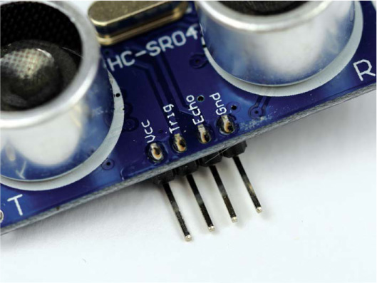
FIGURE 5-3 A close-up of the pins on an HC-SR04 module
You’ll need to power the module using a 5 V source on the Vcc pin. When the HC-SR04 receives the bounce-back pulse, the Echo pin is set to a 5 V logic high, but if we were to connect this directly to the Raspberry Pi, the high voltage would cause serious damage. To avoid this, you’ll need to lower the sensor output voltage to something your Raspberry Pi can handle—that’s where the 1 kΩ and 2 kΩ resistors come in handy. We’re going to use them to build a voltage divider.
Reducing Voltage with Voltage Dividers
A voltage divider is a simple circuit that turns a larger voltage into a smaller one. The voltage divider takes an input voltage and uses two resistors in series to reduce and output that voltage. You use different values of resistors to make the output voltage a certain fraction of the input voltage.
The voltage divider circuit is shown in Figure 5-4. Notice that the output voltage is drawn from between the two resistors.

FIGURE 5-4 A voltage divider circuit
As with most electronics, we use an equation to mathematically relate the two resistors (R1 and R2) to the input and output voltages (Vin and Vout). Physicists don’t mince words, so the equation is simply called the voltage divider equation:
Using this equation, you can work out the exact R1 and R2 resistor values you need to create the desired output voltage. The size of R1 and R2 is actually irrelevant; what matters instead is the ratio of R1 and R2. For example, if R1 and R2 are equal, then the output voltage will be half the input voltage.
WARNING
No matter what resistor values you end up with, it’s always better to have an output voltage that is lower than the target, rather than higher. This is because a lower voltage will not harm your Raspberry Pi or other electronics, whereas a voltage that is too high, even by a small margin, may do so.
Let’s use this equation to work out what resistor values we need for the distance sensor on our robot. You know that the input voltage is 5 V, and the desired output voltage is 3.3 V, so we have two unknowns in the equation: R1 and R2. You can pick a common resistor value for one and that gives us just one unknown, which is much easier to work out. Let’s choose 1 kΩ for R1. By rearranging the equation to solve for R2, you get:
If you plug in the numbers that you know, R2 works out like this:

Finding a resistor with the exact value 1941.176471 Ω is going to be very tricky! So instead we’ll just pick the nearest common resistor value. In our case, a 2 kΩ or 2.2 kΩ resistor will suffice. If in doubt, try to find a resistor that’s nearest, but slightly lower than, the value you need. You can always put your two resistor values back into the equation to work out the output voltage with that pair if you want to double-check.
Wiring Up Your HC-SR04
Now that you have all your necessary components, you can wire up your distance sensor. As always, ensure your Pi and robot’s power are disconnected before you start fiddling around with the wiring and connecting new things.
Rather than plug the HC-SR04 module directly into a breadboard, we’ll connect it using long jumper wires so you can position the distance sensor anywhere on your robot. Using your build from the previous chapter that has the motors wired up, follow these instructions, but don’t attach the sensor to the robot chassis just yet:
- Use a long jumper wire to connect the Vcc pin of your HC-SR04 to the Pi’s +5 V power rail on your breadboard.
Use another long jumper wire to connect the Gnd pin of your HC-SR04 to the ground rail on your breadboard. At this point your wiring should look like Figure 5-5.

FIGURE 5-5 HC-SR04 module connected to +5 V and ground. The motor controller chip and motors are omitted from the diagram, but you should keep them connected to your circuit. The orange stripes represent the area the L293D chip and its wiring takes up.
- Next, use a wire to connect the Trig pin of your HC-SR04 directly to physical pin 16 on your Raspberry Pi. Pin 16 on the Pi is also called BCM 23.
Then attach a jumper wire from the Echo pin of your sensor to a new row on your breadboard. Connect a 1 kΩ resistor by putting one leg of the resistor into the same row as the Echo pin and the other leg of the resistor into a different, unused row of your breadboard. At this point your wiring should look like Figure 5-6.
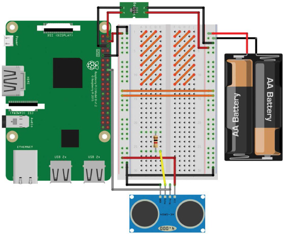
FIGURE 5-6 The Trig pin of the HC-SR04 connected to BCM 23 and the Echo pin connected to a 1 kΩ resistor
- Wire up physical pin 18 (BCM 24) of your Raspberry Pi to the row with the other leg of the 1 kΩ resistor you just connected.
- Finally, place one leg of your 2 kΩ/2.2 kΩ resistor in the row with the 1 kΩ resistor and jumper wire to your Pi’s BCM 24 pin, and place the other leg of this resistor in a ground rail. The complete circuit on your breadboard should look something like Figure 5-7.
Figure 5-8 shows a circuit diagram of the final outcome.
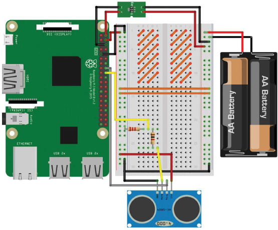
FIGURE 5-7 The completed breadboard diagram with the HC-SR04 and voltage divider in place

FIGURE 5-8 A circuit diagram of the HC-SR04 connected to a Raspberry Pi
Programming Your Raspberry Pi to Read Distance
With your ultrasonic distance sensor now wired up, it’s time to delve into some more Python code to use the sensor. Boot up your Raspberry Pi from a wall outlet, log in, and locate the robot folder you’re saving your programs in. Create a new program called distance_test.py with this command:
pi@raspberrypi:~/robot $ nano distance_test.py
In this project, we’ll still use the GPIO Zero Python library, but we’ll move away from the built-in functions and objects. Instead, I’ll show you how to program and operate the HC-SR04 entirely from scratch!
The code in Listing 5-1 will send out a signal, also known as a ping, and then read and print out the distance of the first object the signal meets. Save this code into the distance_test.py you have already open. Try to use your programming skills to read through and decipher it before moving on to my explanation!
import gpiozero
import time
➊ TRIG = 23
ECHO = 24
➋ trigger = gpiozero.OutputDevice(TRIG)
echo = gpiozero.DigitalInputDevice(ECHO)
➌ trigger.on()
time.sleep(0.00001)
trigger.off()
➍ while echo.is_active == False:
pulse_start = time.time()
➎ while echo.is_active == True:
pulse_end = time.time()
➏ pulse_duration = pulse_end - pulse_start
➐ distance = 34300 * (pulse_duration/2)
round_distance = round(distance,1)
print("Distance: ", round_distance)
LISTING 5-1 Program to measure a single distance
As usual, we begin by importing the gpiozero and time libraries for use throughout the code.
At ➊ and on the following line, we create two variables, TRIG and ECHO, which simply store the pin number that the Trig and Echo pins are connected to, respectively. We capitalize these variables to indicate that they are constants—variables whose values we want to keep the same for the duration of the program.
Capitalizing constants is a programming convention that tells you, and anyone else reading the code, that these values are not changed throughout the execution of the program. It’s worth stressing that because this is a convention, it’s merely a practice that most programmers do, not one enforced by Python. The code would work equally well if these were lowercase, or even a mixture of cases.
The following two lines ➋ set up the GPIO pins connected to the Trig and Echo pins of the HC-SR04. We set up the trigger variable to be an output, since it’s sending out a ping, and echo as an input, since it’s receiving a ping.
To trigger the ping, the HC-SR04 sensor needs a quick 10 µs (1 µs is a millionth of a second: 0.000001 s) pulse that takes place in the next chunk of code ➌.
When the ping has been sent out by the transmitter, the program must wait for the ping to clear the receiver before it starts listening for the echo. This is because the transmitter and the receiver on the HC-SR04 are close together, so in the microseconds after transmission, the sensor can hear the outgoing pulse. We don’t want to record the outgoing pulse accidentally, so we tell the program to wait until it hears the echo and not the original ping. You can think of this as if you and a friend were standing next to each other in a large room and you wanted to listen for an echo. If you were to shout “Hello!” your friend would hear you before you heard the echo from the room. This sort of effect is what we must avoid when using the HC-SR04.
The next section of the code is responsible for making sure we pick up the echo. The while loop ➍ with the condition echo.is_active == False repeats until the outgoing pulse is no longer heard by the sensor. The program then stores the exact time the pulse clears the receiver in a new variable called pulse_start.
With the outgoing pulse now out of the way, the while loop with the condition echo.is_active == True ➎ catches the echo when it returns to the sensor. A second variable called pulse_end is created and is used to record the exact time of the bounce-back pulse.
Then we simply subtract the time the ping was sent out from the time it was received to work out how long it took to return. We store the result in a variable called pulse_duration ➏.
Arguably the most important part of this program is at ➐ where we work out the distance from the time it has taken for the ping to return. We apply the earlier equation to the values we’ve collected in the program:
Rather than use the 343 m/s figure that is the speed of sound, we multiply it by 100 to give us a distance value in centimeters, which is much more relevant to the sorts of distances your robot will be dealing with.
Finally, in the last few lines of the program, we round the distance value to one decimal place and then output it to the terminal.
Running Your Program: Measure a Short Distance
Now that you have the code finished, it’s time to test out the ultrasonic distance sensor and its accuracy.
Place your HC-SR04 parallel to a surface, like a table. Then place a fairly small solid object in front of the sensor and measure the distance with a ruler. In Figure 5-9, I’m using an upright box. My box is roughly 20 cm away from my HC-SR04.

FIGURE 5-9 My HC-SR04 test setup
As ever, to run your program, enter:
pi@raspberrypi:~/robot $ python3 distance_test.py
After a short period, a single distance reading should print to your terminal and the program will end. For me this looks like the following:
pi@raspberrypi:~/robot $ python3 button.py
Distance: 20.1
Your HC-SR04 should have successfully measured the space between itself and the object! Mine was pretty accurate, but you shouldn’t expect 100 percent accuracy with these readings.
If your reading was off by a large margin, try running the program again to see if that output was just an outlier. If you’re still getting wrong readings, check the numbers and equations in your program: are the values correct and have you applied the math in the right way? If the program hangs (does nothing) and never finishes executing, check that your wiring is correct and refer to the instructions earlier in the chapter. Your program may also hang if it never receives an echo. This could be because the distance you’re trying to measure is out of range. However, for indoor use you shouldn’t have any problems.
Finally, if you’re still having issues, consult the code and make sure it’s exactly the same as the program in Listing 5-1. As usual, you can grab the exact code examples from https://nostarch.com/raspirobots/.
MAKE YOUR ROBOT AVOID OBSTACLES
Now that you have mastered measuring individual distances with an ultrasonic distance sensor, you can mount the sensor onto your robot and write a new program that will use the HC-SR04 to avoid obstacles.
By the end of this project, you’ll have a fully autonomous obstacle-avoider! The aim here is to make sure your Raspberry Pi robot gets no closer than 15 cm to any object before it takes evasive action.
Mounting Your HC-SR04 Ultrasonic Sensor
The best place to mount your distance sensor is on the front of the robot in a location that is as central as possible. I recommend using sticky tack or double-sided tape to affix it. The module can sense distance only in a direct straight line, so don’t mount it too high above the floor or your robot is likely to crash into low-lying obstacles.
I have mounted my HC-SR04 on the front stabilizer, as shown in Figure 5-10. The sensor is about a centimeter off the ground. Note that the orientation of your sensor also doesn’t matter: mine is upside down!

FIGURE 5-10 My HC-SR04 mounted to the front of my robot
Programming Your Robot to Avoid Obstacles
To create the obstacle avoidance program, we’ll borrow heavily from the prior section’s code but set the distance sensor to constantly scan for upcoming obstacles.
In Listing 5-1, we worked out how to measure a single distance in 10 lines of code. In our next program, we’ll need to repeat the code continuously to get a constantly refreshing distance from your robot to any upcoming obstacles. We could write out the code every time we need to use it, but that sounds time-consuming and dull, and we don’t even know how many times we’d need to write it out. Instead, there is a way to package up code so you can use it whenever and wherever you need it. Packaging up code like this creates what is known as a function.
A Python function is a block of organized, reusable code that performs an action. Let’s try it out: enter the code for the obstacle avoidance program in Listing 5-2 and save it as obstacle_avoider.py on your Raspberry Pi.
import gpiozero
import time
➊ TRIG = 23
ECHO = 24
trigger = gpiozero.OutputDevice(TRIG)
echo = gpiozero.DigitalInputDevice(ECHO)
➋ robot = gpiozero.Robot(left=(17,18), right=(27,22))
➌ def get_distance(trigger, echo):
➍ trigger.on()
time.sleep(0.00001)
trigger.off()
while echo.is_active == False:
pulse_start = time.time()
while echo.is_active == True:
pulse_end = time.time()
pulse_duration = pulse_end - pulse_start
distance = 34300 * (pulse_duration/2)
round_distance = round(distance,1)
➎ return(round_distance)
while True:
➏ dist = get_distance(trigger,echo)
➐ if dist <= 15:
robot.right(0.3)
time.sleep(0.25)
➑ else:
robot.forward(0.3)
time.sleep(0.1)
LISTING 5-2 Obstacle avoidance program
This program begins by importing the necessary libraries. Then, you identify ➊ and set up ➋ the Trig and Echo pins of the HC-SR04 like you did in Listing 5-1. This also initializes the robot for use.
At ➌, you meet your first Python function, which is organized into a code block. To start a function block, you use the keyword def. This is short for define, as you are defining what the block of code should do.
After def, you enter the name of the function, which, like a variable, can be called anything (provided it doesn’t start with a number). It is best to keep your function names short and to the point. The purpose of this function is to trigger the sensor and return a distance measurement, so I’ve called this function get_distance().
Parentheses follow a function name, and the contents of such parentheses are referred to as the function’s parameters or arguments. These parameters allow us to pass information into a function for later use. In our case, we pass the trigger and echo pin information we set up earlier, so that the function is able to activate and use the HC-SR04 distance sensor.
As with while and for loops, you need to indent the code inside the function so Python knows what code belongs to the function. The indented code begins at ➍ and extends to ➎, and it is exactly the same as the code you used to get a distance reading in Listing 5-1.
At ➎ the code returns the final output of the function: the distance reading. Returning information just means that the output of that function is handed back to the program whenever the function is called. This output could then be printed to the terminal, set to a variable, or manipulated in any way you, as the coder, desire!
We then start an infinite while loop. First we call the get_distance() function and store its result in the variable dist ➏.
Next, we introduce the crucial obstacle-avoiding logic with a conditional if statement ➐. This line translates to: “if the distance between the sensor and an obstacle is less than 15 cm, do the following.” If the condition is true, the two lines inside the statement run and turn the robot slowly right for a quarter of a second.
Finally, the code at ➑ deals with any other scenario. If an obstacle is further than 15 cm away, the robot proceeds forward slowly for a tenth of a second. Obstacle-avoiding programs usually work better when the robot is moving at a slower speed, so we set the robot at 30 percent of its full speed with the (0.3) argument here. If you find this is too slow or too fast for your particular build, feel free to increase or decrease the values inside the parentheses of the motor commands.
Running Your Program: Make Your Robot Avoid Obstacles
Now that the final piece of code is finished, I recommend clearing a suitably large area and then strategically placing obstacles at the correct height for your ultrasonic distance sensor. Take a look at Figure 5-11 for the course I quickly created for my robot.

FIGURE 5-11 My robot facing down some looming upright folders
Run your program with the command:
pi@raspberrypi:~/robot $ python3 obstacle_avoider.py
Your robot should spring to life and proceed forward until it reaches its first obstacle, at which point it should turn until the obstacle is clear and then continue on its path.
Another fun experiment would be to stand in front of your robot and watch it scuttle away from you, no matter how many times you move your feet to be in front of it!
As ever, kill the robot with the command CTRL-C.
Challenge Yourself: Improve the Obstacle Avoidance Program
Our method of obstacle avoidance here leaves a lot of room for improvement!
As mentioned, the HC-SR04 is able to detect distance only in a single straight line, so your robot could miss obstacles that are directly in front of it but too low or too high for it to sense.
Having just one distance sensor is also a limitation. Your robot can detect only obstacles that are straight ahead, so it could easily turn right or left into another obstacle! The more distance sensors you use, the more information the robot has and therefore the more intelligent the running code can be.
Try to tweak the program in Listing 5-2 to make your robot avoid obstacles as efficiently as possible with one sensor. You could edit the minimum distance before evasive maneuvers are taken (the default is 15 cm). Or, you could edit the amount of time the motors are on for each evasion or the direction you turn. Try out different values in these variables and figure out what works best.
When you feel you’ve improved the program as much as you can, you could grab a second ultrasonic HC-SR04 module, wire it up to more of your Pi’s GPIO pins just as before, and customize your code to use this new source of data in addition to the first HC-SR04. If you’re using two sensors, a good place to mount them is on the front corners of your robot, rather than just facing forward.
If you’re still feeling adventurous, you could try a third distance sensor to build an even better picture of the environment your robot is in!
SUMMARY
In this chapter we’ve covered everything from the theory behind ultrasonic distance measurement to programming using functions. You’ve put all of this together to turn your robot into a fully autonomous obstacle-avoiding machine.
In the next chapter, I’ll show you how to make your robot unique by adding programmable RGB LEDs and sound effects!