
7
LINE FOLLOWING
IN THIS CHAPTER YOU’LL GIVE YOUR ROBOT THE ABILITY TO DETECT AND FOLLOW A LINE AUTONOMOUSLY. IT WILL BE ABLE TO IDENTIFY ITS OWN COURSE AND THEN DECIDE EXACTLY HOW TO STICK TO IT.
This is a test of both digital recognition and clever programming. It is also a classic robotics task that is important for everyone to master, from beginners to professionals. By the end of this project you’ll have a fully autonomous robot that will be able to stick to a line like glue!
CREATING A TRACK
As usual, prior to launching into any project, it is important and useful to step back and analyze the task at hand. The aim here is to make your robot follow a line. More specifically, you want to make your robot follow a black line on a white background, like the one shown in Figure 7-1.
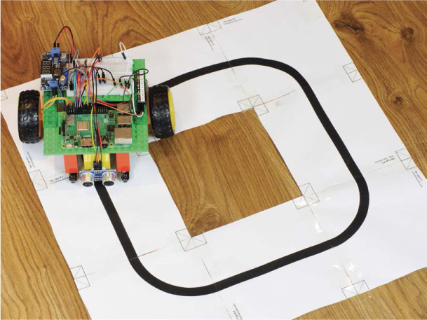
FIGURE 7-1 My robot following a black line
The combination of white and black provides maximum contrast for your robot, enabling us to use simple line-following sensors.
The first thing to do is create a line for your robot to follow. You can make the shape of this track as adventurous as you like. The simplest option is a basic loop, but feel free to get creative, as long as the background is white and the line is black. I also recommend making the width of the line around 1/4 inch.
There are many different ways of constructing a track. You could simply grab a large piece of paper (at least ledger size, roughly 11 × 17 inches) and draw a thick line with a black marker. You could use some black electrical tape on white poster board. You can even purchase premade line-following tracks online. If you have access to a printer, I recommend printing a track out on letter-size paper and assembling it with tape.
I’ve also included the template for a set of tiles you can make into a track of any shape in the resources for this book, which you can access on your Windows, Mac, or Linux PC:
- If you haven’t done so already, download the software bundle from https://nostarch.com/raspirobots/ onto your personal computer.
- Navigate to the folder where the software is stored, and then open the PDF named track_generator.pdf. This is a 34-page document that has a variety of 20 × 20 cm tiles with different lines on them (see Figure 7-2).
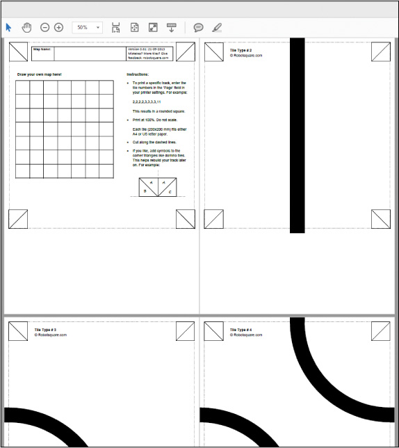
FIGURE 7-2 The track_generator.pdf document
Print out whichever lines you want to put together into a track, cut them out, and then stick them together to form your own custom track. The first few pages of the PDF document show simple paths, such as straight lines and corners, but the farther down you scroll, the crazier the paths get!
For your first track, I recommend keeping it relatively simple. Remember that you can always print out more tiles and make a more difficult course for your robot in the future.
- To create a simple loop, like the one in Figure 7-3, print out four copies of Tile Type #2 (the straight line) and four copies of Tile Type #3 (the basic corner). You should be able to print these pages specifically using the printer dialog box of your PDF reader software. Ensure that each tile takes up one letter-size piece of paper.
- Use scissors to cut around the dotted line of each tile. Then arrange them in a loop, as shown in Figure 7-3, and use tape along the length of the underside to join the edges of the tiles together. Your track is now complete!
WARNING
Make sure you don’t tape over the black line when you connect the tiles, as this may affect the sensors’ performance. Also try to eliminate any gaps or wrinkles between tiles—these can hinder your robot’s movement!

FIGURE 7-3 My assembled basic line-following track
THE THEORY BEHIND LINE FOLLOWING
We’re going to use infrared (IR) sensors to make your Raspberry Pi robot follow the black line. We used similar technology for obstacle avoidance in Chapter 5, when we used ultrasound for the purpose of detecting objects. But instead of sound, in this chapter we’ll use invisible light. Fortunately, much of the same theory you learned previously can be applied here too.
Every IR sensor, like the one in Figure 7-4, has two small bulb-like devices—an infrared transmitter and a receiver, normally arranged and positioned closely together. The transmitter is an IR LED that, when triggered, fires off a pulse of infrared light. The receiver, an IR photodiode, then waits for this transmitted light to return. A photodiode is simply a device that uses light to vary an electric current.

FIGURE 7-4 An IR sensor
Light interacts differently with different types of surfaces. Most notably, light is reflected more by a white surface, and almost totally absorbed by a black surface, enabling the IR sensor to detect black lines on white backgrounds.
As depicted in Figure 7-5, if an IR sensor module is over a white surface, the receiver will detect the reflection of the infrared beam emitted by the transmitter. If the sensor is over a black surface, like the line of your track, the receiver will not detect the reflection. This difference in reflectance allows the sensor module to detect whether or not there is a line in front of it.

FIGURE 7-5 The different behavior of IR light as it meets a white versus a black surface
Mounting a single IR sensor onto the bottom of your robot would enable it to detect the presence of a black line, but if your robot moved so the sensor was no longer directly over the line, it could easily go off-track. With only one sensor, there is no easy way for your robot to detect whether it has gone too far to the left or right of the line. Instead, we’ll use two IR sensors, both mounted on the bottom of your robot at the front, about an inch apart. Two sensors will provide a feedback mechanism with a sense of direction. There are four possibilities for the outputs of these sensors, each of which will guide the robot:
- If both sensors receive a reflected signal and detect white, the robot can assume that the line must be in between the sensors. Therefore, the robot should move forward in a straight line (see Figure 7-6).
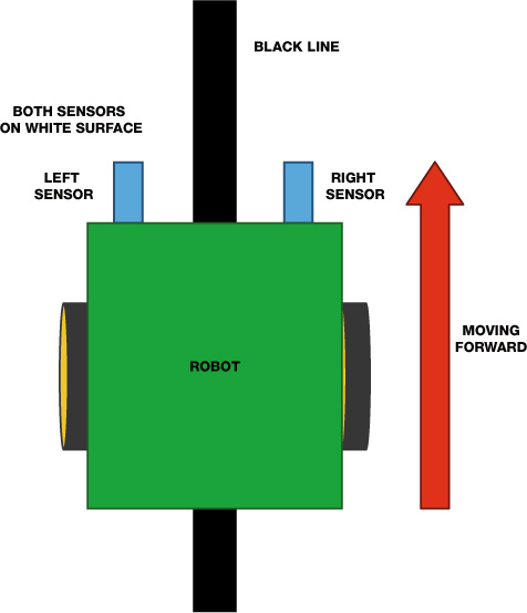
FIGURE 7-6 The robot moves forward when both sensors detect white.
- If the left sensor doesn’t receive a reflected signal but the right sensor does, this must mean that the left sensor detects the line. This indicates that the robot must be veering right, so it should turn left to correct itself, as in Figure 7-7.
- If the right sensor detects the line but the left sensor doesn’t, the robot should correct itself by turning right, as shown at the bottom of Figure 7-7.
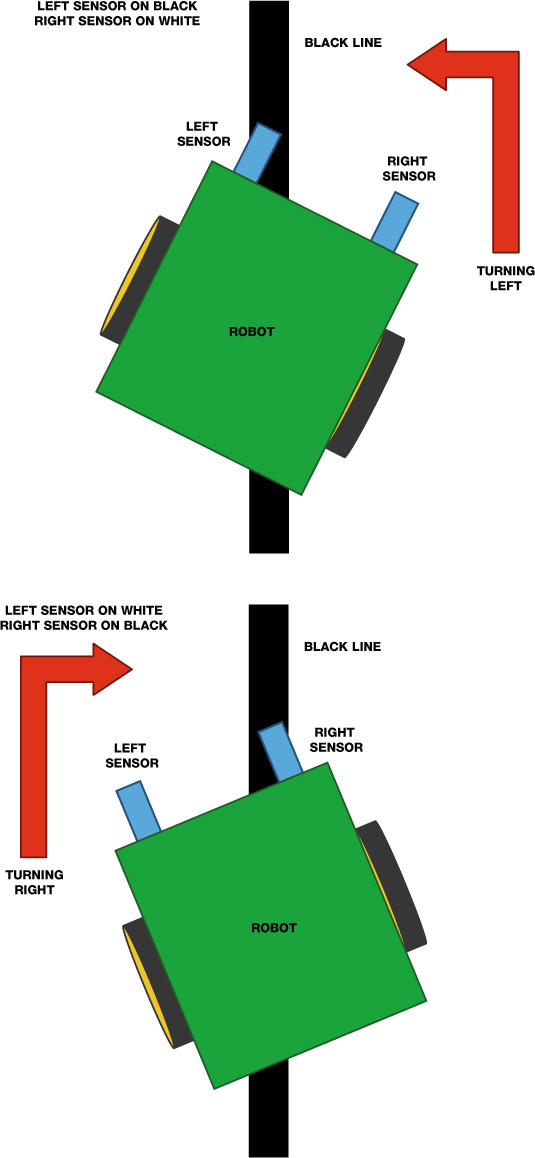
FIGURE 7-7 The robot turns left or right if one of the sensors detects the black line.
- Finally, if neither sensor receives a reflected signal, then they must both be reading black, as shown in Figure 7-8 (this won’t happen if you’re using just a basic loop track). What to do next is up to you, but one option is simply to make the robot stop. If you experiment with other track layouts—for example, a figure 8 shape—you might run into other situations where both sensors detect black. In these circumstances you may want your robot to move forward, turn, or even reverse—play around to find out what works best!

FIGURE 7-8 The robot stops if both sensors read black.
USING AN IR SENSOR TO DETECT A LINE
Before you start mounting two IR sensors to your Raspberry Pi and configuring the code behind a complete line-following robot, let’s wire up just one IR sensor and test its line detection response.
The Parts List
For this part of the project you’ll use only one sensor, but make sure to buy two, as you’ll need both for the next project!
- 2 TCRT5000-based infrared line-following sensor modules
- Jumper wires
TCRT5000-based line-following sensor modules, like the one shown in Figure 7-9, are very common and available online for less than a couple of dollars each. I sourced mine from eBay by searching “TCRT5000 Line Follow Module.” The TCRT5000 part of the sensor name refers to the infrared optical sensor, the small black component on the underside of the board.
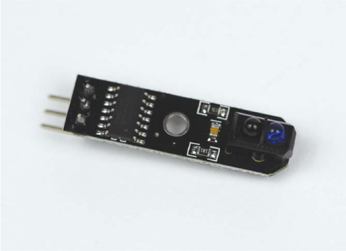
FIGURE 7-9 My TCRT5000 infrared line-following sensor module
Make sure to get a line-following module like the one in Figure 7-9, as this means the functionality of the optical sensor has been neatly packaged into an easy-to-use component. These boards have a simple set of pins and require just three connections (see Figure 7-10).
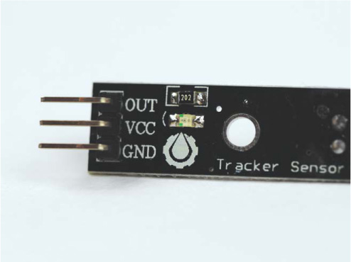
FIGURE 7-10 Pinout of a TCRT5000 IR sensor module
The infrared diode is housed inside the small black component and emits an infrared ray continuously when the module is connected to power. If the light is not reflected back into the sensor, it means a black line must be present and the output pin (OUT) of the module goes low (that is, it drops the voltage). This simple digital logic is ideal and, better still, the module can be powered natively from the Pi’s 3.3 V. This saves us from having to use a voltage divider circuit as we did for the ultrasonic distance sensor in Chapter 5.
NOTE
Remember that you don’t need to disconnect any of your previous circuits, but I won’t show those connections here.
Wiring Up Your TCRT5000 Line-Following Sensor Module
Disconnect your Pi from power and wire up your sensor by following these instructions:
- Use an F-F jumper wire to connect the VCC pin of your TCRT5000 module to physical pin 1 of your Raspberry Pi. This is the +3.3 V connection and provides power to the sensor.
- Use another jumper wire to connect the GND pin of your module to the common ground rail on your breadboard. So far, your wiring should look like Figure 7-11.

FIGURE 7-11 Line-following sensor connected to +3.3 V and GND
- Use another jumper wire to connect the data output pin of your sensor (OUT) to physical pin 21 on your Raspberry Pi. This is BCM 9. Your complete circuit should look like Figure 7-12.

FIGURE 7-12 Completed breadboard diagram with your TCRT5000 line-following sensor module wired up and in place
Programming Your Raspberry Pi to Detect a Line
Now that you have a line sensor connected to your Raspberry Pi, let’s write some code to test its line detection response. Connect your Pi to power via a wall outlet, boot it up and move into your code folder, and then enter the following to create and open a test program called line_test.py:
pi@raspberrypi:~/robot $ nano line_test.py
Add the code in Listing 7-1, which will test your TCRT5000 module. The purpose of this program is to simply output to the terminal to inform the user whether the module has detected a line.
import gpiozero
import time
➊ line_sensor = gpiozero.DigitalInputDevice(9)
while True:
➋ if line_sensor.is_active == False:
print("Line detected")
➌ else:
print("No line detected")
time.sleep(0.2)
LISTING 7-1 Detecting a line
After importing the usual libraries, we set up the line sensor as a digital input on BCM 9 ➊.
NOTE
The TCRT5000 has a detection distance between 1 mm and 8 mm. If the line is farther away from the sensor than this, it is likely to give false positives or negatives.
We then start an infinite while True loop containing the logic of the program. At ➋ we use an if statement to detect whether the line sensor is active. If it isn’t active, it must mean the infrared reflection has not returned and therefore the emitted rays have been absorbed by the black line. Thus, the line has been detected, and we indicate this to the user with the print() statement inside the if statement.
Any other scenario would mean that the line sensor is active and therefore is not detecting a line. The else statement ➌ catches this alternative scenario and outputs to the user that a line has not been detected. The program then waits for a fifth of a second and loops back around.
Running Your Program: Detect a Line!
After saving your program, grab a piece of your track to test out your sensor. To run the program, enter:
pi@raspberrypi:~/robot $ python3 line_test.py
While there is nothing within range of the sensor, it may produce erratic results that will be displayed in the terminal. Bring your piece of track up to the module and move the line over the sensor. You should notice that as you move the piece, the terminal output will change to Line detected:
pi@raspberrypi:~/robot $ python3 line_test.py
No line detected
No line detected
Line detected
Line detected
My particular sensor also has an LED on the top that changes state when the line comes into view.
If you’re having issues with your module and it’s not detecting the line very well, you can try a few things. First, try to limit interference from other light sources by turning the lights off. Alternatively, some TCRT5000 modules have an on-board potentiometer to adjust their sensitivity. This usually looks like a piece of blue/white plastic with a place to insert a screwdriver. Use an appropriate screwdriver or other implement to twist this potentiometer to see if it improves your readings.
MAKE YOUR ROBOT FOLLOW A LINE AUTONOMOUSLY
When your sensor is successfully detecting the line, it’s time to give your robot the ability to follow the track.
By the end of this project, you’ll have connected up a second sensor and programmed the logic behind a fully autonomous program, giving you a line-following robot.
Wiring Up the Second TCRT5000 Line-Following Sensor Module
You’ve already wired up the first TCRT5000 module, so now you only need to wire up the second one. If you don’t have the first one connected, flip back a few pages and follow the wiring guide in the previous project.
The process for connecting your second sensor is as follows:
- Take a F-F jumper wire and connect the VCC pin of your second TCRT5000 module to physical pin 17 on your Raspberry Pi. This is another +3.3 V pin and will power the sensor.
- Now, use a jumper wire to connect the GND pin of the new module to the common ground rail on your breadboard.
- Use a wire to connect the data output pin of your second sensor (OUT) to physical pin 23 on your Pi. This is BCM 11. The wiring for the second sensor, with the first sensor omitted, should look like Figure 7-13.

FIGURE 7-13 Second line-following sensor connected to power, ground, and data
With both line-following sensors connected, your breadboard should look something like Figure 7-14.

FIGURE 7-14 Both line-following sensors connected to the Raspberry Pi
Mounting Your Sensors
Now you need to mount your TCRT5000 modules onto the underside of the front of your robot.
To avoid having to change the code demos later, make sure that the TCRT5000 module you wired up first (the one connected to BCM 9) is on the left side of your robot, and the second TCRT5000 module (connected to BCM 11) is on the right side of your robot.
You can mount these sensors to your chassis in whatever way you like. If you’re using a LEGO-based robot like mine, I recommend attaching two small stalks made of 2×2 LEGO blocks to the bottom of your chassis; mine are roughly four blocks deep. You can then also use sticky tack to affix your modules onto the bottom of the stalks as I have done (see Figure 7-15). I have routed the wires for the sensors through the gap in the middle of my LEGO chassis.
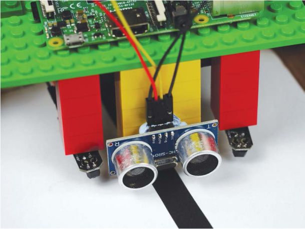
FIGURE 7-15 My IR sensors, mounted on LEGO stalks on the underside of my robot
When mounting the modules, bear in mind that the optimal range from the optical sensor to the ground is between 1 mm and 8 mm. Also remember that the wider the gap between them, the more your robot will stray left or right before it corrects itself. For reference, mine are only an inch or two apart from each other and placed on either side of the front stabilizer.
Programming Your Robot to Follow a Line
With both your sensors wired up and mounted in place, it’s time to write the code that will allow your robot to follow a line.
Open up a new program using Nano and call it line_follower.py as follows:
pi@raspberrypi:~/robot $ nano line_follower.py
The code in Listing 7-2 takes the theory and process behind line following we discussed previously and puts it all into practice. Take a moment to look over the code before you move on to the explanation.
import gpiozero
➊ SPEED = 0.25
robot = gpiozero.Robot(left=(17,18), right=(27,22))
➋ left = gpiozero.DigitalInputDevice(9)
right = gpiozero.DigitalInputDevice(11)
while True:
➌ if (left.is_active == True) and (right.is_active == True):
robot.forward(SPEED)
➍ elif (left.is_active == False) and (right.is_active == True):
robot.right(SPEED)
➎ elif (left.is_active == True) and (right.is_active == False):
robot.left(SPEED)
➏ else:
robot.stop()
LISTING 7-2 Following a line
The code here follows the same logical layout as previous projects in this book. We import gpiozero, then initiate a constant called SPEED and set it to 0.25 ➊. This value, which represents the speed of your robot throughout the program, can be set to anything between 0 and 1.
When you run this code for the first time, you’ll discover that the speed at which your robot is traveling has a huge influence on its line-following ability. By defining a constant at the start of the program, you can easily tweak this setting without rifling through all of the rest of your code later.
At ➋ we set up the first TCRT5000 sensor as a digital input and assign it to the variable left. Then we repeat the process for the second line-following sensor, assigning it to the variable right.
We then begin an infinite while True loop that contains the main logic of the program: a series of if statements. This is where the line-following theory is implemented.
The code at ➌ deals with the scenario in which both sensors are active and therefore both reading white. With no line detected, the program assumes that the line is directly underneath and between the sensors, and the robot proceeds forward at its given speed.
Next, an elif statement ➍ catches the case when the left sensor is off and thus detecting black, but the right sensor is active and thus detecting white. In this scenario, we need to execute a corrective maneuver to turn the robot right.
Then, an almost identical elif statement ➎ accounts for when the right sensor detects the black line. The corrective maneuver turns the robot left this time.
Finally, at ➏ we use an else statement to deal with the only option left: neither sensor is active and therefore both are reading black. The exact behavior of your robot after this is up to you to define. In my code I have decided to stop its movement.
Running Your Program: Make Your Robot Follow a Line!
With your line-following program now complete, connect your robot to battery power and place it on the test track you created earlier. For the best results, ensure that the black line is directly underneath your robot and between the two TCRT5000 sensors (see Figure 7-16).

FIGURE 7-16 My robot in place, ready to follow the line
Run your program with this command:
pi@raspberrypi:~/robot $ python3 line_follower.py
Your robot should now be moving around your track completely autonomously and sticking to the black line with no trouble at all. Admire your work as the robot scuttles around in an endless loop!
NOTE
You may find that you need to stick your track down to the floor so that the wheels of your robot don’t move it around. If this is the case, just use some tape to securely and nonpermanently fix it in place.
EXPERIMENTING WITH LINE FOLLOWING
Line following is a classic lesson in robotics, but as you can probably tell, it can take a serious amount of tweaking and hacking to improve the effectiveness and results. You’ll probably have already noticed that you can alter many different factors to change the performance of your line follower. Here are some of my suggestions.
Change the Track
While a simple loop is a great first-time test bed, it quickly becomes boring. To challenge your robot, try creating a more adventurous track. Use tighter corners, longer straights, and more advanced geometries! You can even get inspiration for new layouts from real race tracks—for example, the Monaco Grand Prix circuit in Figure 7-17.

FIGURE 7-17 The Monaco Grand Prix circuit represented as a black line that your robot could follow
Change the Speed
The faster your robot is moving around the track, the less time it has to react to the information that the TCRT5000 sensors provide. At faster speeds, you may find that your robot drifts away from the line. You can change its speed by going back into the program and editing the SPEED constant defined at the top of the code.
You may also find that you want to change the speed of your line follower for different movements. For example, your robot may perform better if it goes around corners slower. You could add this functionality into the program by creating another constant called CORNER_SPEED and using it in the functions for turning left and right.
As you fine-tune the speed of your line-following robot, time it as it goes around the track. See how fast you can get it to accurately follow the line. You could even race against some friends and have a line-following racing tournament to see whose code is best.
Change the Position of Your Sensors
The farther apart the IR sensors are, the more your robot will stray from the line before executing a corrective maneuver. This could potentially lead to your robot fish-tailing along the line in a zigzag pattern. Experiment with moving the modules closer together to see how this affects how well your line follower operates.
You should find that the closer together the modules are, the more the robot will turn left and right to get back on track. This will mean that your robot follows the line more accurately, but at what cost? Does it affect the speed at which it can complete the course? Play around and find out!
Add More Sensors
If you want to take this even further, add more line-following sensors. Just like with obstacle avoidance, the more information your robot has about its position, the more intelligent the program behind it can be. If you can add a third, fourth, or even fifth TCRT5000 module, then you can judge the degree by which your robot has strayed from the line. You could then use this information to change the magnitude of course corrections. For example, if the robot is far away from the line, it could execute a faster corrective maneuver.
SUMMARY
In this chapter you’ve given your robot the ability to autonomously follow a line. We have covered everything from the theory of line following to the sensors you need and the code behind them.
In the next chapter I’ll show you how to use the official Raspberry Pi Camera Module to recognize and follow a colored ball!