In this chapter, we will learn about types of joints components and their properties. Joints are important components of Unity3D and provide different types of joints. We will learn about all these joints with interesting examples, that is, by creating a door animation with a hinge joint, a ball's spring movement using a spring joint, and bone movement using character joints.
In this chapter, we will learn more about the following joints:
- Types of joints
- Configurable joints
- Handling movement and motion of configurable joints
Now, we will learn about different types of joints.
Joints are one of the most important components of Unity3D. In this chapter, we will learn more about joints.
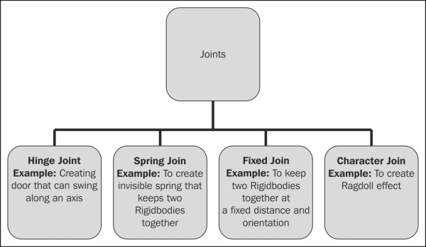
Apart from the previously mentioned joints in the preceding diagram, there is also a configurable joint that allows you to create complex joint configuration using different joints. Let's take a look at the different types of joints with examples.
The fixed joint is used to group two Rigidbodies together in their bound position. We use a fixed joint to parent the object in the hierarchy. By using this joint, we can lock the game object in the world. In this example, we are going to learn how we can implement a fixed joint. Let's get started:
- Create a new scene and save it as
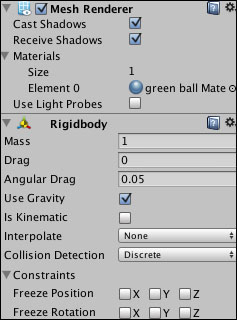
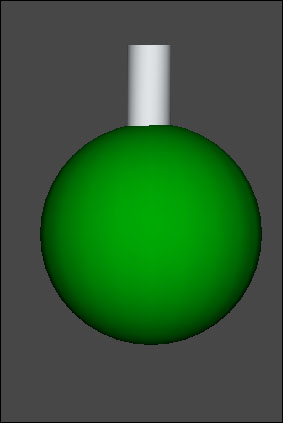
Fixed Joint Example. - As shown in the following screenshot, create a Sphere game object and assign a Rigidbody component to it.
- As you can see in the following screenshot, apply the green ball Material option and the Use Gravity option from Rigidbody for the sphere game object.
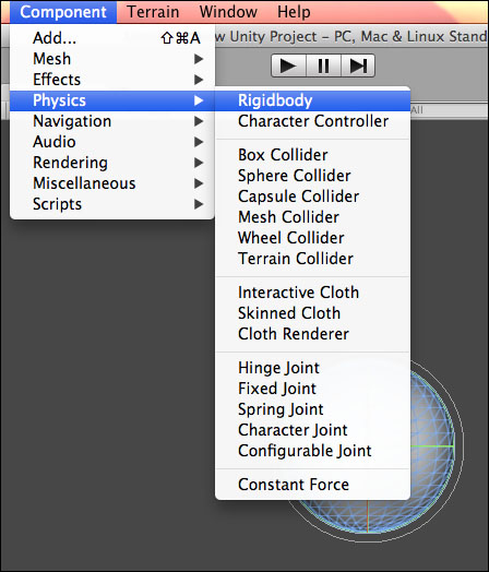
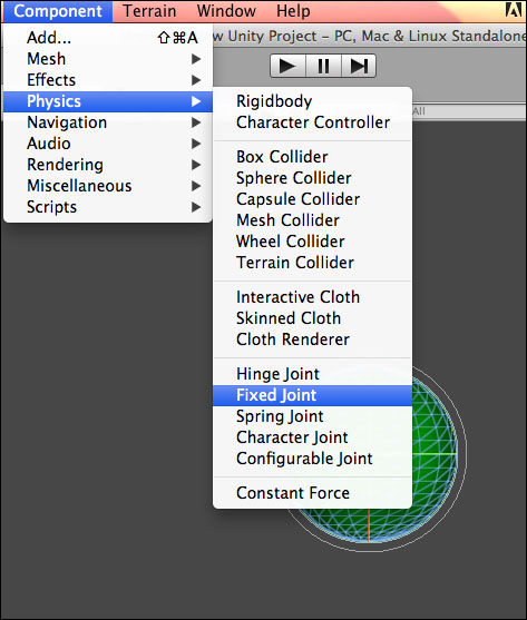
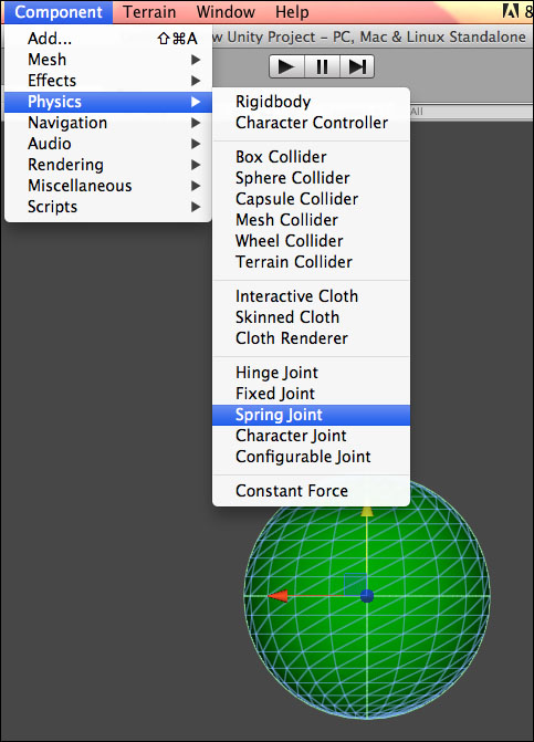
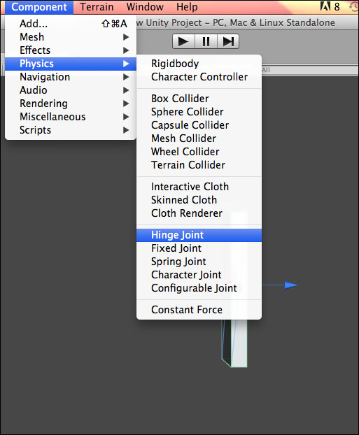
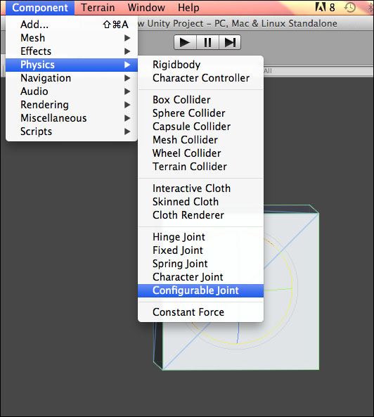
- To apply a fixed joint as shown in the following screenshot, click on Component and select Physics. From the Physics menu, select Fixed Joint.
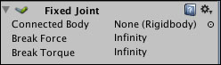
- After applying Fixed Joint, look at the Inspector panel; you will see the options with the components, as shown in the following screenshot:
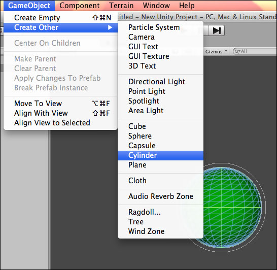
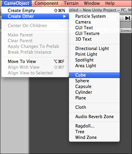
- Connected Body refers to the other Rigidbody on which Fixed Joint is dependent upon. Now we need to create a connector for it. Let's create a Cylinder game object that will work as a connector to the sphere. As shown in the following screenshot, click on GameObject and then select Create Other to create the Cylinder game object:
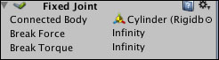
- Now drag Cylinder to Connected Body. This will create the connector for the Sphere game object. The other options Break Force and Break Torque are required amount of force and torque which can break the joint. For now, we have set it to Infinity to make it nonbreakable.
- Run the project and you will see that the sphere falls with the cylinder because it is fixed to the cylinder.
In the preceding example, we have learned how we can implement the fixed joints in development.
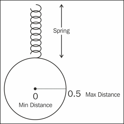
Let's move to the next joint, which is a spring joint. A spring joint makes the Rigidbodies move like a spring. The applied game object gets pulled towards a particular position because of this joint. Spring joints, as their name implies, work on the principle of a spring where the specified game object tries to reach a target position, which we set in the scene view, while the attached Rigidbody will pull it away from the target position. As shown in the following diagram, if we apply a spring joint on a sphere, it will show the behavior of a spring and try to move toward the particular position. Here, Min Distance will be the center of sphere while end of radius will work as Max Distance. We can modify the value of minimum and maximum distance as per our requirements. The working of this joint is shown diagrammatically, as follows:
In the following example, we are going to create a sphere that will have a spring joint:
- As shown in the following screenshot, let's create a sphere with a Rigidbody and apply Spring Joint:
- As shown in the following screenshot, we can set an Anchor value. An orange square above the sphere represents the anchor. Let's reset the Y value and run the project. You will see the sphere's movement with the spring.
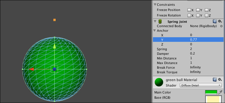
- We can set the number of springs by putting values for the Spring option. We have set it at
50to increase the bounciness. Similar to other joints, Break Force and Break Torque are the force and torque required to break the joint.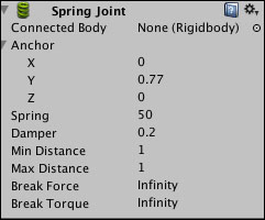
In the preceding example, we can see the different properties of a spring joint and their uses.
We have learned about a fixed joint and a spring joint. Now, let's learn about a hinge joint.
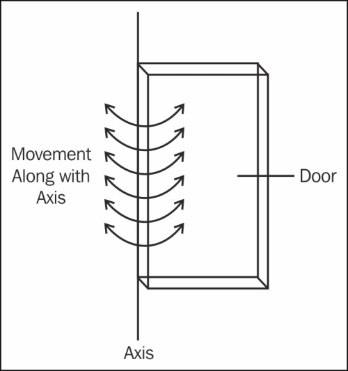
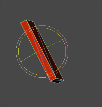
Normally, hinge joints are used to create a swinging door and a wrecking ball. The hinge joints move along with the axis, as shown in the following diagram. If we apply a hinge joint on a door, it will move along with the axis.
Let's learn to apply a hinge joint to a game object and also see which properties are associated with hinge joints:
- Create a new scene and save it as
Hinge Joint. - Create a Cube game object and apply a Rigidbody component to it. Scale it to give it the shape of a door.
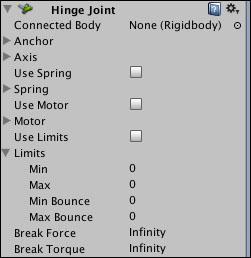
- Now apply Hinge Joint, as shown in the following screenshot:
- After applying material to it, give it a color, rotate it, and run and test the movement of the door.
The hinge joint possesses several properties as options. We can use the properties of Hinge Joint as per our requirements. Here, Connected Body refers to the other Rigidbody with which the joint is dependent. Anchor refers to the point at which the connected bodies can rotate. Axis defines the axis of rotation. To apply spring force to a target angle, we apply Spring. To slow the spring recoil, we set the Damper value; Motor to apply motor force; and Limits to specify the angular limit.
The character joints work on the principle of a ball and socket movement with limit, which are normally used for Ragdoll effects. This consists of variables that handle the effects or movement.
Note
Ragdoll Physics is a type of procedural animation that is often used in video games and animated films. You can find details of using Ragdoll Wizard of Unity3D at http://docs.unity3d.com/Manual/wizard-RagdollWizard.html.
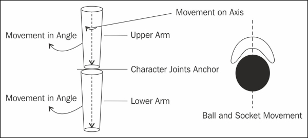
We are going to create a character joint for an arm. There are two types of movement, as shown in the previous diagram. We divide this arm in two parts—one is Upper Arm and the second is Lower Arm. We will see that there are two types of movement in this case—one is movement with the axis and the other is movement in angle or we can say swinging movement.
Let's handle the arm animation with Unity Physics character joint:
- Create a scene and name it
Character Joint example. - Now create an empty game object and name it
Arm: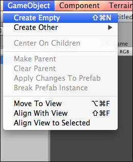
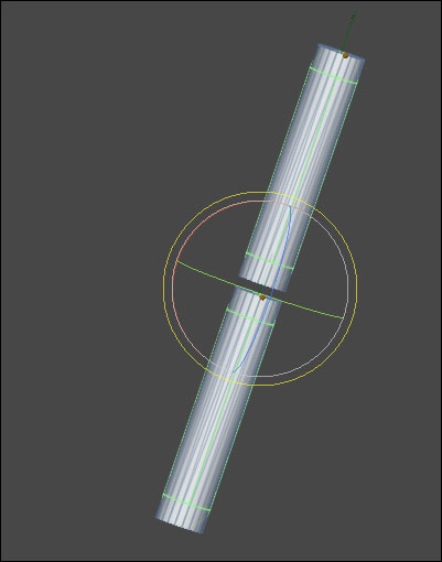
- Now, create a Cylinder object and apply Rigidbody on it. Name it
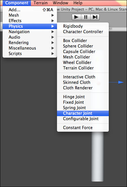
Upper Arm. - Click on Component and apply Character Joint on it.
- Now, create another Cylinder object and again apply Rigidbody on it. Name it
Lower arm: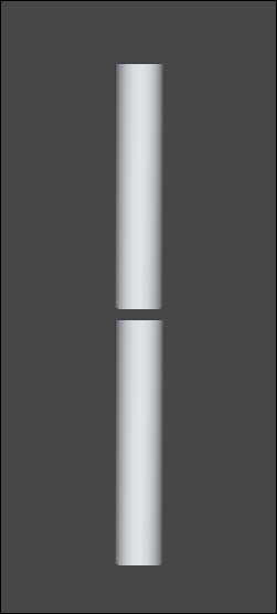
- Click on Component and then apply Character Joint on it:
- Now let's play with the properties of character joints to get the required effect:
- By default, Connected Body connects to the world. It represents the Rigidbody on which the joint is dependent. Let's drag the Upper arm Rigidbody to the connected body option of Lower arm.
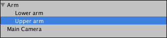
In the following screenshot, Upper arm is Connected Body for the lower arm:
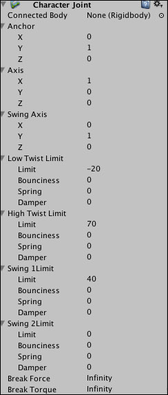
Anchor is where a joint rotates around. Axis which have twist axis and swing axis; using twist axis, we handle twisting while using swing axis, we handle swinging. Low Twist Limit is for the lower limit of the joint and similarly, High Twist Joint is for the higher limit of the joint. Again, Swing 1Limit is for the lower limit around the swing axis and Swing 2Limit is for the upper limit around the swing axis.
- Rotate the Arm game object and test the scene.
In the previous example, we have learned how we can use the character joint.
Configurable joint possesses features of all the joints. It works on the principle of two primary functions which are movement/rotation restriction and movement/rotation acceleration. We can see that there are multiple interdependent properties in the configurable joints. To get the required effect, we will need to play with the values of its different properties.
Let's see what do we mean by movement/rotation restriction. For this, perform the following steps:
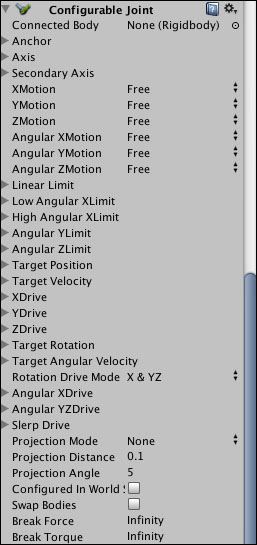
Using the previously shown different properties, we can achieve the desired effect for your project. Now, let's see how we can handle the movement and rotation of different properties in the project.
We can restrict movement as per the axis. XMotion, YMotion, and ZMotion allow you to do that and while using Angular XMotion, Angular YMotion, and Angular ZMotion, we can define the rotation. These properties can be set to Free which means unrestricted, Limited which means restricted based on limits, or Locked which means restricted to zero movement.
We can use the Limit properties to restrict the motion. Using Linear Limit, we can define the maximum distance from the origin point. Using Bounciness, Spring, and Damper, we can define the behavior of the object when it reaches the limit on any of the limited motion axes. To stop the object's movement on the border, we set all these values to 0. Using bounciness, we set the bounce back behavior of the object from the border similarly. Spring and Damper will create springing forces to apply the spring effect border.
We can use the Limit properties to restrict the rotation. Limiting rotation works almost the same as limiting motion but the differences are the Angular Limit properties. We can restrict translation along all three axes by defining the Linear Limit property, and we can also restrict rotation along each of the three axes by defining the Angular Limit property per axis.
Using the Angular XMotion limitation, we can define a Low Angular XLimit and a High Angular XLimit. For the y and z axes, the low and high rotation limits will be the same, which we set using the Limit property of Angular YLimit or Angular ZLimit.
Using drive properties, we define the acceleration by defining the Target value. To specify object movement or rotation in terms of moving the object toward a particular position or rotation, we need to define the Target value to move toward, and using a drive to provide acceleration that will move the object toward that target.
Using the XDrive, YDrive, and ZDrive properties, we define movement along that axis. Spring value defines the object's motion toward the Target position. Similarly, if we are using velocity in its mode, its maximum force value defines acceleration toward the velocity.
Rotation acceleration properties contain the Angular XDrive, Angular YZDrive, and Slerp Drive function similar to the translation Drives. There is one small difference. Slerp Drive behaves differently. It has different functionality than the Angular Drive functionality so we cannot use both together.