The hardware
Abstract
Chapter 6 begins with a brief review of the ARM processor and the specifications of the Mini2440, the recommended target board for this section of the book. We also review some other inexpensive ARM-based single board computers to show why the Mini2440 was selected. Next comes a discussion of NAND versus NOR flash, and the characteristics of file systems for flash memory.
Keywords
ARM architecture; single board computer; NAND flash; NOR flash; YAFFS; u-boot
Beware of programmers carrying soldering irons.
Anonymous
Embedded computing covers an extremely wide range of hardware, from the (probably) 8-bit processor that powers your automatic coffee maker, to the (perhaps multicore) 32-bit or 64-bit processor in your cell phone or tablet, up to the massively parallel processing environment that runs the telecommunications network. In this chapter, we will get to work on the embedded target board that we will use in the next few chapters for applications programming.
The ARM Architecture
ARM is a 32-bit and 64-bit reduced instruction set computer (RISC) architecture developed by ARM Holdings, a British company originally known as Advanced RISC Machines. It is said to be the most widely deployed 32-bit architecture in terms of numbers produced. According to Wikipedia, over 50,000,000,000 ARM processors had been produced as of 2014.
The basic idea behind RISC architecture is that a simpler instruction set requires fewer transistors, which in turn consume less power and take up less die space. The relative simplicity of the RISC architecture makes ARM processors suitable for low power applications. As a result, they have come to dominate the mobile and consumer electronics market. About 98% of all mobile phones use at least one ARM processor1.
ARM Holdings itself does not make chips. Rather, it licenses the architecture to a number of semiconductor manufacturers including Applied Micro, Atmel, Freescale, Marvell (formerly Intel), Nvidia, ST-Ericsson, Samsung, and Texas Instruments, among others.
Open Source Hardware
Open source software has been around for at least 25 years. More recently, some groups have started developing open source hardware, generally small, single board computers based on ARM processor chips.
BeagleBoard
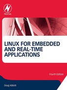
The BeagleBoard is based on the TI (Texas Instruments) OMAP3530 system-on-a chip (SOC) that combines an ARM Cortex-A8 CPU with a TI TMS320C64x digital signal processor. It was initially developed by TI as an educational tool, and the design was released under the Creative Commons license. The original BeagleBoard was release in July of 2008 (Fig. 6.1).
Specifications (Rev. C4)
• Processor: TI OMAP3530 at 720 MHz
• DVI-D using HDMI connector, max. resolution 1280×1024
• Power: 5 VDC, barrel connector
Requiring only 2 W at 5 V, the board can also be powered through its USB port.
There have been several versions of the BeagleBoard released over the years. These include:
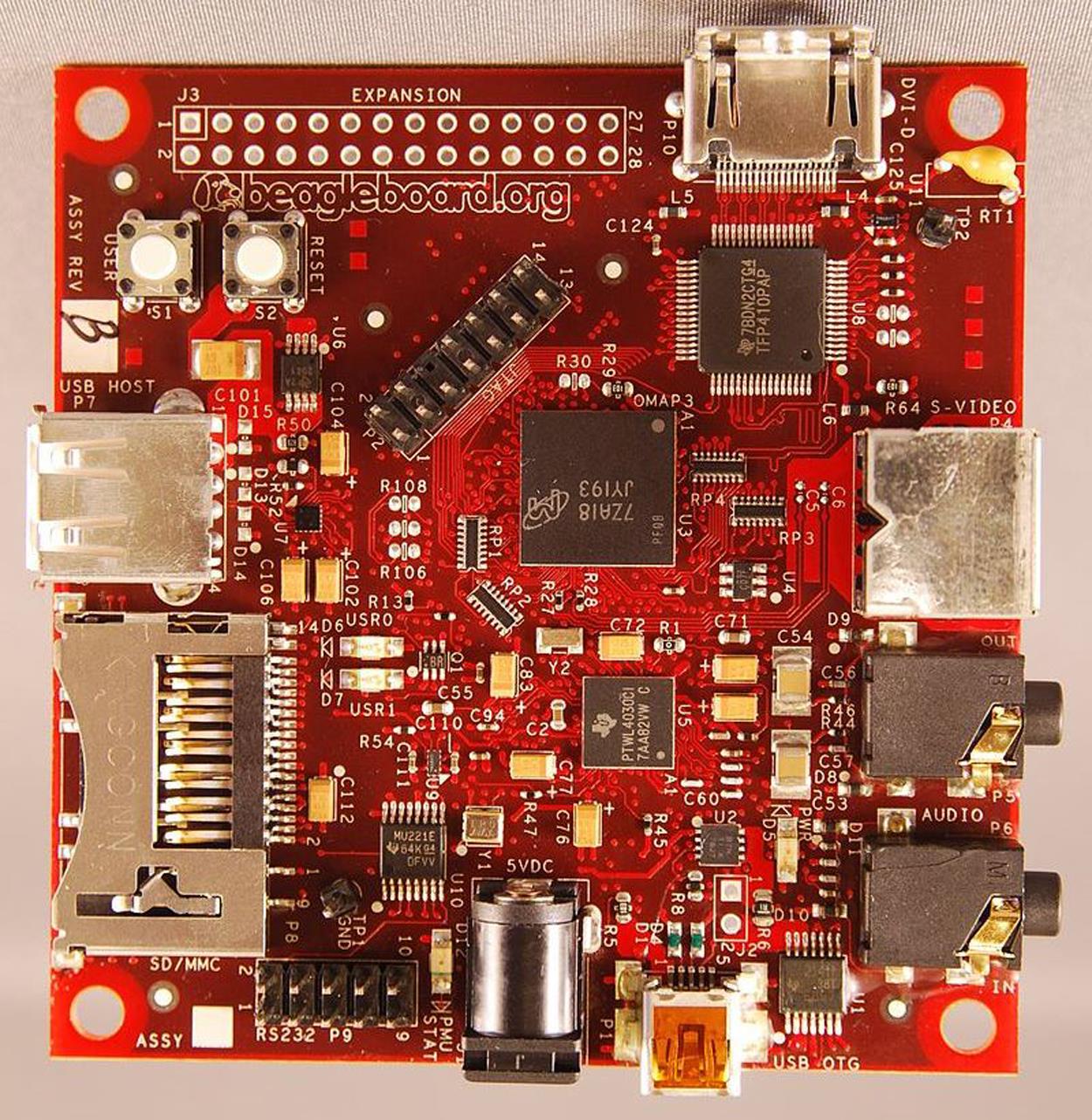
BeagleBoard-xM
• Processor: TI DM3730 at 1 GHz (Fig. 6.2)
• 4 GB Micro SD card with Angstrom Linux distribution
• DVI-D using HDMI connector, max. resolution 1280×1024
• Power: 5 VDC, barrel connector
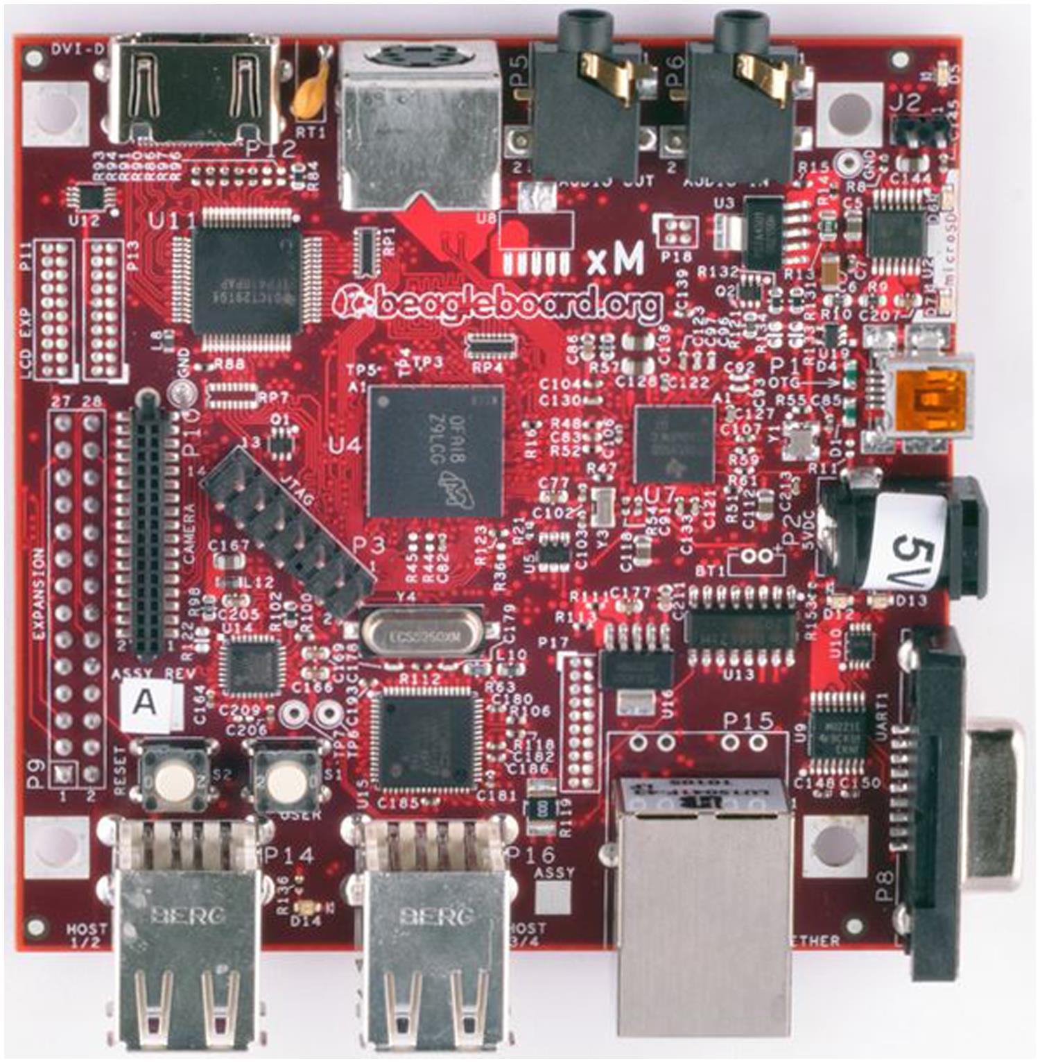
BeagleBone
A “bare bones” version (Fig. 6.3). The BeagleBone has a pair of 46-pin expansion connectors into which expansion boards called “capes” may be inserted. Up to four capes can be stacked at once. A large number of capes are available. See the Resources section for a link to a page listing them.
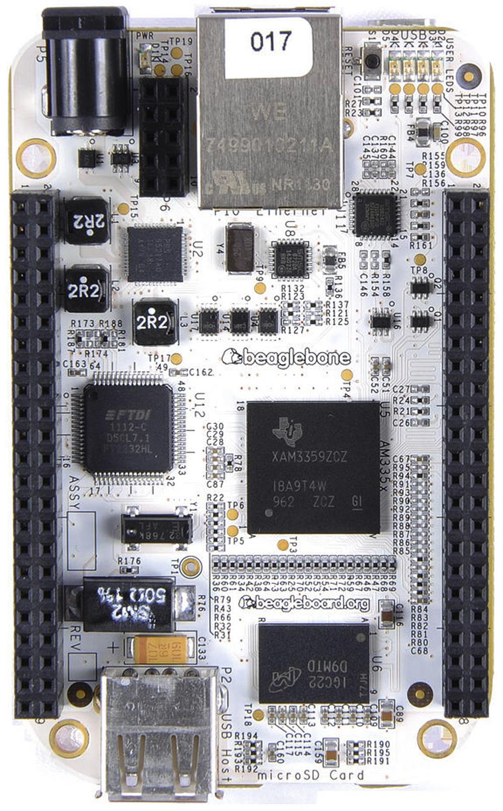
BeagleBone Black
Successor to the BeagleBone. The Black offers more features at a lower price. The hardware-related exercises in the book are designed for either the BeagleBone or the BeagleBone Black (Fig. 6.4).
• Processor: TI AM335x ARM Cortex-A8 at 1 GHz
• 2 (Rev. B) or 4 (Rev. C) GB eMMC flash. Rev. B ships with Angstrom, Rev. C ships with Debian
• TTL serial port on 6-pin header
• JTAG on 20-pin header (unpopulated)
• Power: 5 VDC, USB, barrel connector, or battery

We will use the BeagleBone Black to explore embedded Linux for much of the rest of the book. Some of the exercises require a potentiometer connected to an analog input. The easiest way to do that is with a prototyping cape, such as the one offered by Sparkfun (see Resources for web address). You will also need to order two 46-pin headers.
The other accessory you may want is a USB to serial TTL cable. While the BeagleBone Black does emulate a serial port on its USB client, that does not access the u-boot bootloader, which we will need to make some modifications to. Again, there are multiple sources for this cable, among them Sparkfun.
Gumstix
The Gumstix series of SBCs are produced by a company of the same name. The name comes from the size of the boards, which is about the size of a stick of chewing gum. There are currently three product lines:
• Overo series based on the TI OMAP ARM Cortex A8 processors
• 11 models priced from $109 to $179
• DuoVero series based on TI OMAP4430 ARM Cortex A9 dual core processors
• Three models priced from $169 to $199
• Verdex Pro series based on Marvell PXA270 Xscale processors
Owing to its small size, the computer board itself does not have any standard I/O connectors. Connection to the board is through two small 70-pin AVX connectors that mate with an expansion board that provides the usual connections (Fig. 6.5).

Additional specifications
Several expansion boards are available with a wide range of connection options including Ethernet, USB, stereo audio in and out, camera interface, and DVI video, among others. The expansion boards are priced from $27.50 to $229.
Raspberry Pi
In March of 2012 the big buzz in the world of ARM-based SBCs was the Raspberry Pi, a $35 board that runs standard Linux distributions such as Fedora and Debian. Developed in the UK by the Raspberry Pi Foundation, the objective is to provide a low-cost computer that will stimulate the teaching of computer science in schools.
The device went on sale February 29, 2012, and almost immediately the initial production run of 10,000 units sold out.
Like all of the open source boards we have looked at, the RPi has gone through a substantial evolution. The latest revision, called the Raspberry Pi 3 Model B, was released in February of 2016 (Fig. 6.6).

Specifications
Setting up the BeagleBone Black
Setting up the BeagleBone Black is pretty straightforward. The Quick Start guide included with the board is really about all you need to get started. So, start by connecting the board to your workstation using the supplied USB cable. Initially, the four blue user LEDs will come on solid. After about 10 seconds, they will assume their default assigned function:
Fig. 6.7 shows the layout of the board with specific reference to connectors, switches, and indicators. The only cable supplied with the board is a USB cable. The simplest setup is to simply connect the board to your workstation through the USB cable, which supplies up to 500 mA of power for the board.

The board’s USB slave port is a multifunction device that appears as:
• Mass storage device that appears at boot under the normal path for removable devices (/run/media/<your_user> in CentoOS 7)
Mount the board’s mass storage device, and scan through the START.htm page in Firefox. Among other things, it will instruct you to execute the script file mkudevrule.sh. This is necessary in order to utilize the board’s serial and network ports. It would probably be a good idea to reboot your workstation after this, to make sure that the changes have been implemented.
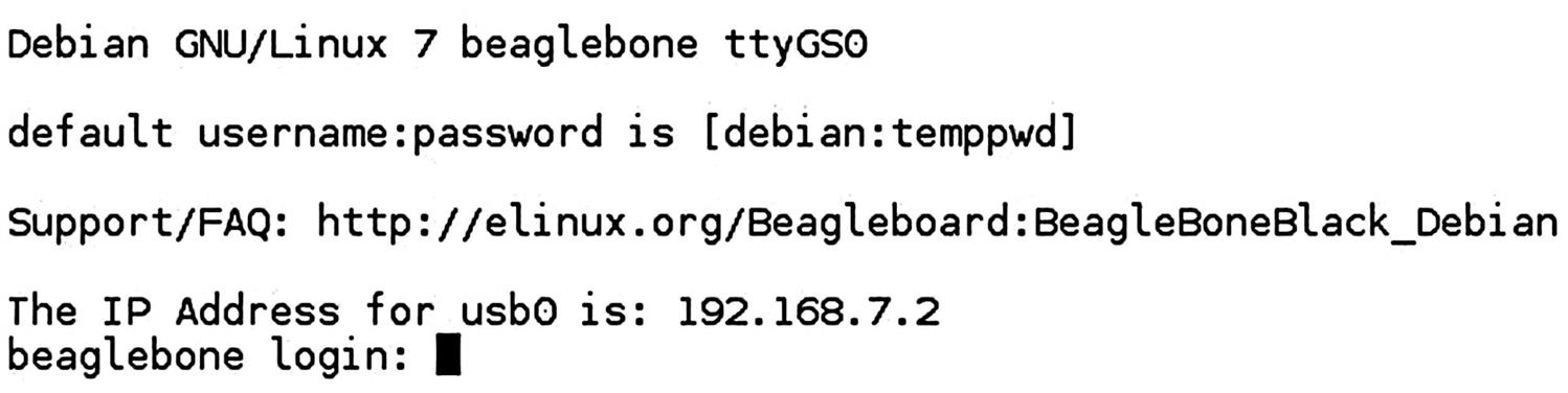
Now fire up minicom. You should see a screen like Fig. 6.8. The board gives you a normal user password, or you can log in as root with no password. Try a few shell commands just to prove it really is a Linux shell. Execute uname –a to verify that you really are talking to a BeagleBoard.
Finally, in another shell window, execute ssh –l [email protected]. You will be asked for the same password as the minicom shell. Or, again, you can log in as root with no password.
So, you have two options for getting shell access to the target board: the serial port, or SSH over the network. Both of these operate over the same USB interface.
You will also want to connect your BBB to your network through the Ethernet port, so you can Dynamic Host Configuration Protocol (DHCP) an IP address.
Flash Memory and File Systems
BeagleBone Black Memory Configuration
The BeagleBone Black has several forms of memory, both volatile and nonvolatile, as shown in Fig. 6.9. There are two forms of nonvolatile storage: a 4 KB EEPROM (Electrically Erasable Programmable Read-Only Memory) that stores ID data about the board itself, and a 4 GB eMMC (embedded Multi-Media Card) NAND flash that uses a byte-wide port for address and data. In addition to the on-board NAND flash, there is a microSD card slot for additional storage. Finally, there is 512 MB of DDR3 RAM for working memory.

The eMMC is divided into two partitions: a 32 MB VFAT formatted boot partition and the remainder is formatted as an ext4 root file system. Once the board is booted, the boot partition is visible to your workstation as a USB drive. It is also mounted in the BBB’s file system as /boot/uboot.
Preparing the Board
Caveat
In the remainder of the book, I’ll be describing Debian version 7.4 released in 2014. There are two reasons for this:
I tried the latest release, Debian 8.7, but ran into problems that I couldn’t resolve and couldn’t find help with on-line. Specifically, I couldn’t mount the root file system over Network File System (NFS), although all of the documentation says it should work fine. Clearly, after you finish the book, you’re free to install whatever version strikes your fancy. But for now, we are going to stick with version 7.4.
We are going to make some changes to the way the BBB boots up. Specifically, instead of mounting the root file system from the eMMC, we are going to mount it over NFS from the workstation. This requires modifying the boot process.
The Boot Process
The BBB uses a very capable open source boot loader called u-boot, which we will get into in more detail in a later chapter. U-boot makes extensive use of environment variables to control the boot process.
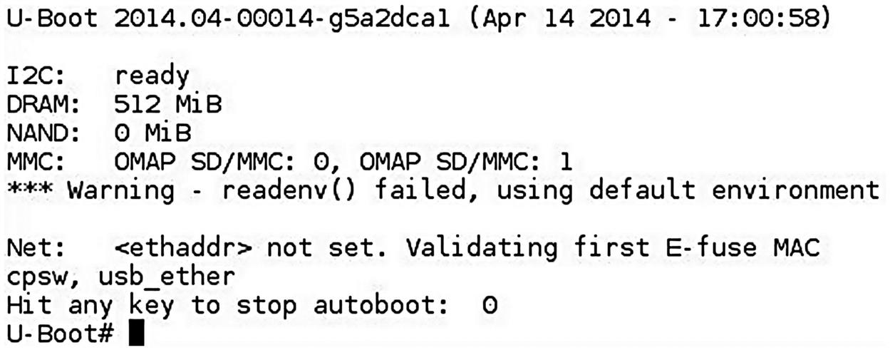
Hook up your serial cable per the instructions that came with it. Change the minicom Serial Device from ttyACM0 to ttyUSB0. Reset the board, but this time quickly hit a key. I usually hit the space bar. This brings up the u-boot prompt, along with some basic board information as shown in Fig. 6.10.
Enter the command printenv to see the environment variables. There are a lot of them. Environment variables can be set with the setenv command:
The value of an environment variable is referenced by enclosing it in ${}. An environment variable can contain one or more u-boot commands separated by ‘;’. Such a variable can be “executed” with the run command. A variable can also contain the run command, allowing it to execute other variables.
U-boot has a very extensive command set, much of which is detailed in Appendix A. For now, type help to see a complete list.
U-boot tries to read its environment from a NAND flash that is not installed on the BBB. That fails, and so it uses a default environment built into u-boot itself. One consequence of this is that we cannot permanently modify the default environment without modifying and rebuilding u-boot itself. We can, of course, modify variables each time we boot.
But note the variable bootenv=uEnv.txt. When u-boot has finished setting up the default environment, it reads the file specified by bootenv for additional instructions. This file resides in the eMMC’s boot partition that is visible in your workstation.
Issue the boot command to let Linux boot up. Mount the boot partition, and open uEnv.txt with an editor. The interesting piece is down at the end, the variable uenvcmd. This is the last variable u-boot executes, and so it should boot up the kernel in some fashion.
In the default case, uenvcmd loads three files from the eMMC: the kernel, the initial RAM disk image (initrd), and something called a flattened device tree (fdt). mmcargs sets the bootargs variable, which is passed to the kernel as it boots. The bootz command transfers control to the kernel, passing it the addresses of the initrd and fdt. So, to modify how the root file system gets mounted, we modify uEnv.txt, or perhaps better, supply a different one.
In your samples/directory, open the file uEnvnet.txt and find uenvcmd. About the only thing that is different is it runs netargs instead of mmcargs. netargs sets up bootargs to specify the file system type as nfs, and provides the location of the server and path to the file system directory. Up around the middle of the file is a set of variables that define the address of the server and the path to the root file system, which you will probably want to change.
Historically, I’ve always defined a fixed IP address for the target board. For some reason that does not work with the BBB, and so you see at the tail end of netargs ip=dhcp.
In principle, you should be able to write directly to the boot partition from your workstation, but I found that to be less than reliable. What I did was to create a directory on the BBB under /home, and then mount my workstation’s home directory there over NFS. But, before you can do that, you have to install a package called nfs-common. Your BBB must be connected to the Internet. Then execute:
Of course, if you are logged in as root, you can drop the sudo. You might want to put the mount command into a shell script, as you may be executing it a number of times. Now you can copy uEnvnet.txt from the workstation to /boot/uboot on the BBB:
Always execute sync after changing the /boot/uboot directory, or your changes may not get to the flash before you reboot. I suggest you do not flat out replace the original uEnv.txt just yet and in fact, you might want to keep a copy of it.
Differences Between Version 7.4 and Version 8.7
Now that we understand the boot process, I can say a little about the differences between Debian 7.4 and the latest release, 8.7. The principal difference I see between the two is in how the boot code is structured. As described above, version 7.4 splits the eMMC into two partitions, one for booting and one for the root file system. In version 8.7, there is only the ext4 root partition that includes the kernel image, the initrd, and device table files. The u-boot image is not visible. It is clearly there, but it is hidden.
The default u-boot environment has expanded substantially. In 7.4 it is 4.6 KB, and in 8.7 it is 20.5 KB. The intention is to make it easier to write uEnv.txt files, which is fine, but it also makes the default environment itself much harder to understand.
The Root File System Image
Even though we will be mounting the root file system over NFS, you will need to load an image file to the eMMC in order to create a boot partition. But first you need to load the image file to a microSD card. A 4 GB card is sufficient. You should use a USB card reader, as there have been reports that the built-in readers on some laptops are not reliable under Linux. The card should show up as /dev/sdb. If not, you can execute:
just after inserting the card, and it should show what device was just recognized.
Browse to debian.beagleboard.org/images and download BBB-eMMC-flasher-debian-7.4-2014-04-14-2gb.img.xz. Uncompress the file with the xz command thus:
This yields one file, BBB-eMMC-flasher-debian-7.4-2014-03-26-2gb.img. Write this file to the microSD card with the dd command:
This will take a fairly long time. When it is finished, there will be two partitions on /dev/sdb; a bootable FAT partition named BEAGLEBONE, and an ext4 partition named eMMC-Flasher. This image is specifically for flashing the eMMC.
Insert the microSD into your unpowered BBB. The BBB documentation says that to boot from the microSD card, you must hold down the boot pushbutton while applying power. In my case, the mere presence of a microSD card causes the board to boot from the card. Power it up. The kernel will boot up as normal, and present a login prompt. But the pattern of the LEDs indicates that something else is going on. That something else is flashing the eMMC. When the four LEDs come on steady, the flashing is finished. Power down the board, remove the microSD card and repower the board. It boots Debian 7.4 from the eMMC.
Finally, you need to get the target root file system on to your workstation under your home directory. You do not want to copy it from the microSD card, because that image is specifically intended for flashing the eMMC. What you can do is copy from the BBB eMMC over the network to your workstation. Create a subdirectory under your home directory to match what you specified for rootpath in uEnvnet.txt. Now copy the entire target file system into that directory. I suggest copying each top level directory separately, rather than everything in one big cp –r command. Note, incidentally, that there are several top level directories that are empty. You can just execute a mkdir command for these. A few directories require some special attention:
• /boot – Do not copy the /uboot directory. Just create an empty directory.
• /dev – You only want the part of /dev that is on the microSD card. The remainder of /dev is populated by a program called udev.
• /home – Do not copy your home directory that you mounted over NFS.
You will need to edit /etc/fstab as root user. There will be a line that looks something like this:
Your UUID will probably be different. This line is trying to mount the root file system from a disk drive, which not surprisingly interferes with mounting over NFS. Just comment the line out and save the file.
Boot to the NFS File System
Reset the board into the u-boot prompt if you are not already there. Execute the following commands:
The reason for not overwriting uEnv.txt right now is that there might be something wrong with your uEnvnet.txt, in which case you will need to boot back into the eMMC file system. When you are confident that uEnvnet.txt is working correctly, you can rename it uEnv.txt and boot directly into the NFS file system.
Interestingly, the boot up seems to be somewhat more verbose with the NFS file system than with the eMMC file system.
As a final step, move the samples/ directory into your target file system under /home.
What Can Go Wrong?
It is not unusual to encounter difficulties when bringing up an embedded target board such as the BeagleBone Black, even though the designers have gone to great lengths to make the process as painless as possible. The most common problems fall into two broad categories. The first is the serial port. Make sure the baud rate is set correctly. This is generally not a problem, because 115 kbaud seems to be the default for minicom. A more common problem is not turning off hardware flow control.
Common networking problems include having Security Enhanced Linux enabled, and/or the firewall turned on. This will prevent the target from NFS mounting its root file system. As a starting point, disable SELinux, and turn off the firewall. Later on you can configure either of these features to allow NFS mounting, but still provide some level of protection.
Make sure the IP address is correct. Actually, this should not be a problem, because you will be getting an IP address through DHCP.
With the target board fully configured and connected to the workstation, we can turn our attention to the task of writing applications. That’s the subject of the next chapter.