5
Spontaneous Emergence of Chirality
Mohan SRINIVASARAO1
1 School of Materials Science and Engineering, School of Chemistry and Biochemistry, Center for Advanced Research on Optical Microscopy (CAROM), Georgia Institute of Technology, USA
5.1. Introduction
This chapter deals with the spontaneous emergence of chirality or chiral structures from materials that are achiral. We will primarily focus on the appearance of chiral structures in the context of the simplest of the liquid crystalline phases, the nematic phase, where the constituent molecules possess long-range orientational order. In doing so, we intend to take a broader approach, where our observations are contexualized, taking into account the historical developments dealing with “chirality”. We will begin with a discussion of chirality since the early 1800s, highlighting the many contributions of French scientists in the 19th century to molecular chirality. Since the manifestations of “chirality” have often been through optics, and, in particular, to the rotation of a light beam’s plane of polarization, it would seem not only appropriate but also required that we consider the history of these ideas in some detail.
Following these ideas, we shall discuss the appearance of chiral structures from achiral materials, in particular, from lyotropic nematic liquid crystals (LCs). A term that is often used to describe such appearances of chirality is “Chiral Symmetry Breaking”, a term that can be quite confusing, as well as, perhaps, being used rather incorrectly. We will spend a bit of time to note that this term, in principle, should not be used to describe the appearance of chiral structures from achiral materials. Then we will provide a discussion of the appearance of chirality or chiral structures from nematic LCs under various confinement geometries, from cylindrical to rectangular to square capillaries, and end with misconceptions dealing with optical activity.
5.2. Chirality: a historical tour
It is reasonable to ask why should we be concerned with the historical aspects of chirality or handedness in this short chapter. I would argue that it is due to the elegance of the nature of science. Sir Hans Krebs, Nobel Laureate in Physiology or Medicine (1953) (Krebs 1970), provides an answer: “those ignorant of the historical development of science are not likely ever to understand fully the nature of science and scientific research”. Since the history of chirality, or molecular chirality, is particularly rich in beautiful experiments (and elegant theories), it would appear worthwhile to take a detour into the pages of history.
The German philosopher Immanuel Kant is perhaps the first to have expounded on the property of handedness, during the latter part of the 18th century, dealing with a debate among the philosophers of the time, on the nature of space (Kant 1991). In referring to the two hands, which are mirror images of each other, Kant wrote sie können nicht kongruieren (they are not congruent), implying that mirror image objects that cannot be made exactly congruent are incongruent counterparts. Examples of such “incongruent counterparts” are asymmetric solid figures with identical shapes and sizes but opposite handedness, examples of which include snail shells, twining plants and right and left hands, among others. The science of molecular chirality encompasses a vast area of science (Wagnière 2007), with profound implications for biology (Mason 1991; Guijarro and Yus 2009).
An article entitled “Chemistry at its most beautiful” published in the pages of Chemical and Engineering News, on the 25th of August 2003, presents the results of a survey of the journal’s readers on “the most beautiful experiments in the history of chemistry” (Freemantle 2003). At the top of list, in first place, was Louis Pasteur’s manual separation of sodium ammonium tartrate crystals into two sets that were mirror images of each other. A prominent historian of science noted the scientific significance of Pasteur’s discovery by stating: “the experiment was the effective beginning of stereochemistry and understanding molecules in three dimensions” (Freemantle 2003). Another prominent chemist and historian notes, “Pasteur’s separation of optical isomers opened an area of chemical structure particularly important to organic chemistry and biochemistry”.
The now familiar narrative of Pasteur’s remarkable discovery starts when the 25-year-old Pasteur undertook a project to crystallize a number of different compounds, and he started his work on tartaric acid. It turns out that crystals of this organic acid are abundant in the sediments of fermenting wine. Often crystals of a second acid, called “paratartaric acid” or “racemic acid” (the etymological root of “racemic acid” comes from the Latin word racemus, meaning “cluster of grapes”) are also found in the sediments of wine barrels. At the time, it was noted that the chemical compositions of the two acids, tartaric and paratartaric, were identical. However, in solution, the two showed a striking difference; tartaric acid rotated a beam of polarized light passing through it to the right, while paratartaric acid did not rotate the plane of polarization. This, clearly, was quite puzzling and led Pasteur to wonder how this could be? Pasteur, at this point, was clearly convinced that the internal structure of the two compounds must be different, and that this difference might expose itself in the crystalline form. It must be noted that a number of experts in the developing field of crystallography had studied these compounds and noted that no difference could exist.
Pasteur painstakingly examined the crystals and found the difference he was looking for. He found that all pure tartaric acid crystals looked identical but noticed that there were two types of crystals in paratartarate. One type was the mirror image of the other, a difference that Pasteur was looking for. Pasteur then proceeded to separate the left and right crystals manually under the microscope, to form two piles of crystals (Figure 5.1). He then proceeded to show that, in solution, one form rotated light to the left and the other to the right, the magnitude of the rotation, measured with a polarimeter shown in Figure 5.2, was nearly equal. This simple experiment showed that organic molecules with the same chemical composition can have spatially different forms, and with this work was launched the new science of stereochemistry.

Figure 5.1. Hemihedral crystals of sodium ammonium tartrates. Redrawn after Pasteur
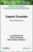
Pasteur’s findings led him to realize that the molecules of tartaric acid had to be chiral, in effect, he had discovered molecular chirality. However, it should not escape the attention of the reader that Pasteur made his discovery of molecular chirality at a time when little was known about the chemical structure and atomic bonding, as well as the spatial arrangement, and we would have to wait until 1874 when Van’t Hoff and LeBel proposed, independently and almost at the same time, the asymmetric carbon atom as a basis for molecular chirality (Ball 2005). As noted by Van’t Hoff and LeBel, in such an atom the four substituents differ, and if the arrangement of the substituents on the carbon is not planar, two non-superposable mirror images are possible, thus introducing chirality (see Figure 5.3).

Figure 5.2. Schematic of a primitive polarimeter that is used to measure the optical rotation
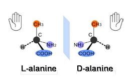
Figure 5.3. Two mirror images of an amino acid, alanine
Stereochemistry, broadly viewed, deals with the study of the spatial arrangement of atoms that form the structure of the molecules and their manipulation, and is an important branch that deals with chirality or chiral molecules. Stereochemistry is a complex and rich discipline, and its language is just as rich and complex. When Pasteur discovered molecular chirality (chirality, as a term, was not in use at the time of Pasteur’s ground-breaking discovery), he recognized the need for a term to denote the phenomenon of handedness in chemistry and crystallography, and adopted the term dissymétrie (dissymmetry) and dissymétrique (dissymmetric) for the purpose. It should also be noted, at this point, that Pasteur did not coin the word dissymétrie, which appeared in the scientific literature in France well before Pasteur.
It appears to have been coined by Frédéric Jacob Soret to describe a form of the crystals of aragonite (a form of CaCO3) as dissimétrique [sic], to indicate that the crystals lacked certain symmetry properties relative to the crystal axis. The terminology dealing with stereochemistry, as discussed in many texts, is often confusing or misused; however, we shall not be bogged down in such a discussion here. Nevertheless, these are important discussions, and hence the reader is referred to a number of excellent reviews on the nomenclature and terminology, and its egregious errors in the literature and in textbooks (Lowry 1964; O’Loane 1980; Gal 2013).
William Thompson and Lord Kelvin introduced, in 1884, the terms “chiral” and “chirality” (Thomson and Lord Kelvin 1904):
I call any geometrical figure, or group of points, chiral, and say that it has chirality, if its image in a plane mirror, ideally realized, cannot be brought to coincide with itself.
“Chiral” and “chirality” are derived from the Greek word, “cheir”, meaning “hand”. Pairs of human hands are the most common examples of Kelvin’s geometrical type; they are “identical opposites”, mirror images of each other (Thomson and Lord Kelvin 1904). The word “enantiomorph”, closely associated with chirality, captures its Greek-derived meaning of “opposite form” (enantios morphe).
Clearly, this is what Pasteur meant by “dissymétrie moléculaire”. Pasteur, in a lecture delivered to the Société Chimique de Paris in 1860, entitled Recherches sur la dissymétrie moléculaire des produits organiques naturels, speculated on the atomic arrangements in dextro- and levo-organic compounds that are optically active:
Are the atoms of the right acid grouped on the spirals of a dextrogyrate helix, or placed at the summits of an irregular tetrahedron, or disposed according to some particular dissymmetric grouping or other? We cannot answer these questions. But it cannot be doubted that there exists an arrangement of the atoms in a dissymmetric order, having a non-superposable image, and it is no less certain that the atoms of the levo-acid realize precisely the inverse dissymmetric grouping to this. (Ramsay 1981)
It was Van’t Hoff and LeBel in 1874 (Lowry 1964; Ball 2005) who provided the solution with the proposal of a tetrahedral carbon. Since the time of Kekulé (~1858), it was known that carbon atoms generally form bonds to four other atoms. Van’t Hoff suggested that the stick diagrams that were in use to depict organic molecular structures as an arrangement in space should be extended into the third dimension, out of the plane of the paper. Van’t Hoff’s proposal amounted to having the four bonds pointing to the corners of a tetrahedron. This, said Van’t Hoff, is how organic compounds acquire a handedness, resulting in the optical rotation.
5.2.1. Chirality and optics
As is clear from the discussion thus far, optics played a key role in Pasteur’s discovery of molecular chirality. His discovery benefited immensely from the illustrious 19th century French traditions in the fields of crystallography, optics and theories of the arrangement of atoms in organic molecules. Hence it would seem beneficial to understand the key events that were instrumental for Pasteur’s discovery. As already described, Pasteur measured the rotation of the plane of polarization of light on passing through a chiral medium. George Wald (Wald 1957), in a paper titled, “The origin of optical activity” begins by stating: “no other chemical characteristic is as distinctive of living organisms as is optical activity”. Wald was referring to the phenomenon that has been studied since the early 1800s, when the French physicist Jean Baptiste Biot discovered that some substances of biological origin displayed optical rotation (Applequist 1987). Instruments designed to measure such optical rotations, referred to as polarimeters (key components are illustrated in Figure 5.2), have been used to study the interaction of polarized light with chiral or optically active materials. Some of the key events that led to the science of polarimetry and to the study of chirality (or optical activity) in various disciplines are described below:
|
1669 |
Erasmus Bartholinus discovers the double refraction of Iceland spar, but he was unaware of the polarizations of the beam split by double refraction. |
|
1690 |
Christiaan Huygens provided a theory for the double refraction discovered by Bartholinus. He also showed that the two doubly refracted beams had different polarizations. |
|
1808 |
Étienne-Louis Malus discovered that light, when reflected from glass and metallic surfaces, is polarized. According to Arago (1859), “[O]ne day in his house in the Rue d’Enfer, Malus happened to examine through a doubly refracting crystal (Iceland spar), the rays of the sun reflected from the windows of the Luxembourg Palace. Instead of two bright images which he expected to see, he perceived only one – the ordinary, or the extraordinary, according to the position which the crystal occupied before his eye. This singular phenomenon struck him much”. Malus deduced the law that bears his name, Malus’ Law, that the intensity of plane-polarized light transmitted by a linear analyzer is proportional to the cosine square of the angle θ between the polarization direction and the preferred direction of the analyzer: I/I0 = cos2θ. It is quite remarkable that the first quantitative expression was deduced with the human eye as the detection system! |
|
1809 |
Francois Arago observed that light from the sunlit sky was partially polarized, and established the fact that the polarization maximum (vertically polarized) is located about 90° from the sun. He also discovered the presence of a point of zero polarization (Arago’s neutral point) at a position of 20°–25° above the antisolar direction. |

Figure 5.4. (Left) Rotation of plane of polarization of light in an optically active medium. (Right) Rotation for different colors by a plate of quartz 1 mm thick. Redrawn after Jenkins and White (1981)
|
1811 |
Francois Arago discovered the rotary polarization of quartz for a light beam traveling along the optic axis of the crystal. By now, it was known that when light propagates parallel to the optic axis of the crystal, there is no double refraction. However, Arago noted that, in the case of quartz, when a plane-polarized beam traveled along the optic axis, the plane of polarization rotated about the direction of the beam (see Figure 5.4 (left)), meaning it emerged vibrating in a different plane from which it entered the crystal. In a beautiful narration of Arago’s work, Kahr writes (Kahr and Arteaga 2012): “the white light, analyzed with a Rochon prism fashioned from doubly refracting Iceland spar crystals, produced pairs of coloured images with hues depending on the position of the prism relative to the input polarization. The colours were indifferent to the azimuth of the quartz plate. Arago had seen for the first–time optical rotation and optical rotatory dispersion.” This is schematically illustrated in Figure 5.4 (right) where |
different wavelengths are rotated to a different extent when the beam exits the crystal.
Scientists of the time were fascinated by the blue color of the sky and were having trouble identifying the reasons for this color until John Strutt (also known as Lord Rayleigh) in 1871 provided an explanation based on molecular scattering, refuting Tyndall’s argument that the blue color of the sky is due to foreign matter in the atmosphere. The color of the sky, coupled with the polarization of the sky remained unexplained and John Tyndall, in 1869 (six decades after Arago’s discovery of the polarization of the sunlit sky), stated, “these questions constitute in the opinion of our most eminent authorities, the two great standing enigmas of meteorology” (Young 1982).
|
1812 |
Sir David Brewster discovers the relationship between refractive index and polarizing angle (Brewster’s Law). |
|
1812 |
Jean Baptiste Biot repeats the experiments of Arago and demonstrates that the colors seen by Arago come about due to the direction of polarization of the light rotated and that each wavelength is rotated through different angles. Biot noted that this effect is similar to the dispersion of colors by refraction in a glass prism, but is due to optical rotation and is known as optical rotatory dispersion. Biot also discovered that there are two types of quartz, different only in how they rotate the plane of polarization of the incident polarized light beam. |
|
1815 |
Biot, while studying quartz immersed in organic liquids, made a far-reaching discovery: that the liquids themselves were optically active. These included distilled oils of turpentine, lemon, sugar solutions and camphor. What was remarkable at that time was that, unlike quartz, these organic substances were optically active as liquids that did not exist in two forms of opposite handedness. |
The discovery of optical activity in organic molecules by Biot posed two major questions, the answers to which were not obvious at the time: what is the nature of light that makes the phenomena of polarization and optical rotation possible, and what property of the organic molecules enables them to rotate the plane of polarization of the light?
1821
–1822 | Fresnel, following Thomas Young’s notion that light is a transverse wave, implying that the direction of oscillation is perpendicular to the direction of propagation, provided the first theoretical interpretation of Malus’ observations. Fresnel provided an explanation for the optical activity by considering that linearly polarized light can be thought to be composed of two circularly polarized rays, rotating in opposite directions – a left-circular and right-circular polarized ray – and the plane of polarization of the linearly polarized ray is rotated, should the two circularly polarized components travel in the medium at different velocities. |
In an effort to demonstrate this conjecture, Frensel constructed a three-piece prism, consisting of one piece of levorotatory quartz and two pieces of dextrorotatory quartz, cut in a way that light travels through the prism along the optic axes of all three parts. Linearly polarized light entering the prism was found to split into two circularly polarized rays of opposite sense when they exited the three-piece prism, thus demonstrating that the two components experience different velocities. It is remarkable that Fresnel’s conjecture of optical rotation as being equivalent to “circular double refraction” still forms the basis for modern theories of optical rotation.
Fresnel also offered an alluring explanation for why the refractive index might be different for the two circularly polarized rays: “this may result from a particular constitution of the refracting medium or of its integral molecules which establishes a difference between the sense of right to left and that of left to right; such would be, for example, a helical arrangement of the molecules of the medium which would present opposite properties according as these helices were right-handed or left-handed” (italics added by the author for emphasis).
Helices? One could ponder how Fresnel came to view certain matter to be present in a helical arrangement, as very little was known about the geometrical arrangement of molecules in matter at that time. Nature, of course, provides a number of examples of helices, such as in snail shells, the climbing habits of plants and whirlpools. In the case of quartz, Fresnel’s ideas, while wading into new areas of knowledge, also turn out to be correct, as schematically illustrated in Figure 5.5.
Viewing along the optic axis of quartz-crystal model, one finds columns of silicon and oxygen atoms built up in spirals. The known chemical structure of crystalline quartz is SiO2. Modern X-ray diffraction has provided the structure of crystalline quartz, where the SiO4 tetrahedra are arranged along a helical axis, with three tetrahedral per turn. To propose “a helical arrangement of molecules” must have been natural to Fresnel, as it is a shape that can occur in two forms, right-handed and left-handed, being mirror images of each other, just as the two directions of the rotation of polarization are mirror images of each other.
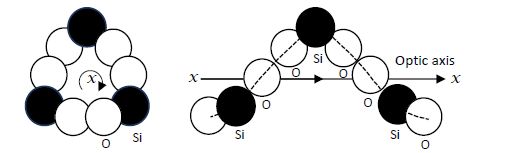
Figure 5.5. Spiral arrangement of silicon and oxygen atoms along the optic axis in quartz crystals. Redrawn after Jenkins and White (1981)

Figure 5.6. Experiment of Ghosh and Fischer: (a) Schematic of the geometry used to image the double refraction from chiral fluid. (b) Intensity plots of a laser after passage through (I–IV) 8, 12, 16, and 20 interfaces, respectively. Image IV shows two well-separated profiles that are right and left circularly polarized. Reprinted with permission from Ghosh and Fischer, (2006)
Almost two centuries after Fresnel’s remarkable experiment, Ghosh and Fischer (2006) demonstrated that a chiral liquid also splits a linearly polarized light beam into two circularly polarized beams of opposite handedness. Figure 5.6(a) depicts the experimental arrangement and the results. In order for the splitting of the beams to be large enough to be seen by the detector, Ghosh and Fischer used multiple refractions through prismatic cuvettes filled with optically active solutions (limonene, in the experiments), a scheme similar to that used by Fresnel. In Figure 5.7(b), the splitting of the beams of a 405 nm diode laser beam is clearly demonstrated and the two beams are indeed circularly polarized with opposite handedness.
|
1845 |
Michael Faraday discovers the phenomenon that now bears his name, of an induction of optical rotation for a polarized light beam traversing an (isotropic) medium parallel to the magnetic field lines. Years prior to this discovery, Faraday also discovered electromagnetic induction. It is said that Einstein considered Faraday (along with Maxwell) responsible for the greatest change in the axiomatic basis of physics since Newton. |
|
1848 |
Louis Pasteur describes the hemihedral crystals that are optically active, leading to the landmark discovery of “molecular chirality”. |
|
1852 |
Sir George Stokes describes the four Stokes parameters that describe the polarization of electromagnetic radiation. |
|
1864 |
James Clerk Maxwell writes a six-page memoir entitled “A dynamical theory of the electromagnetic field”, a development of a mathematical theory for the propagation of electromagnetic waves. |
|
1869 |
The Scottish physicist, John Tyndall, performs brilliant experiments to demonstrate that the scattering of light by particles depends on the size of the particles, as well as being the first to realize that a cloud of fine particles polarizes the beam completely at a scattering angle of 90° from the propagating direction. Tyndall published a study of photochemical smogs under the title “On the blue colour of the sky, the polarization of skylight and on the polarization of light by cloudy matter generally”. This study would prove to be quite decisive to the subsequent analysis of scattered light by Lord Rayleigh. Specifically, Tyndall was the first to observe the bluish color of light upon the scattering of natural light. |
|
1871 |
Following Tyndall’s work, not being satisfied with the explanation of the blue color of the sky, John Strutt (later known as Lord Rayleigh) provides an explanation of the blue color of the sky, deriving an expression for the wavelength dependence of the intensity of scattered sunlight. |
|
1893 |
Lord Kelvin, in a lecture entitled, “On the molecular tactics of a crystal”, introduces the concept of chirality and the words “chiral” and “chirality”, words that did not exist at the time of Pasteur. |
|
1911 |
In a paper entitled, “On the metallic colouring in birds and insects”, Albert A. Michelson (1927) observed that some scarab beetles possessed a metallic reflection and that the reflection was circularly polarized. He went on to suggest, correctly, that, “the effect must therefore be due to a ‘screw structure’ of ultra microscopic, probably of molecular dimension”. Neville and Caveney (1969) pursued the origin of circularly polarized reflection in several scarab beetle cuticles, and found that a “helicoidal structure” is responsible for the color (selective reflection) and the handedness of the circular polarization, and pointed to the analogy of the scarab beetle cuticles to those of cholesteric liquid crystals or chiral nematic liquid crystals. |
5.2.2. Chiral symmetry breaking and its misuse
The general phenomenon of the spontaneous emergence of chiral structures or objects from achiral or “racemic” initial states is often referred to as spontaneous chiral symmetry breaking. As has been noted (Walba 2003; Ávalos et al. 2004), this term can be befuddling at best and incorrect at worst. This befuddlement arises because an object or a system with “chiral symmetry” is achiral (i.e. it is congruent with its mirror image) in the physics community, while chemists, utilizing point groups to describe congruence with its mirror image, however, use the term “reflection symmetry” to describe an achiral object. It seems useful at this point to quote from Mislow’s text (Mislow 2002) from the section entitled “Reflection Symmetry-Point Groups”:
An object is said to have reflection symmetry if it is superimposable on its reflection or mirror image. Reflection symmetry is revealed by the presence of a rotation–reflection axis (also called mirror axis, improper axis or alternating axis) Sn: in a molecule having such an axis, reflection in a plane perpendicular to that axis followed by rotation by 360°/n will convert the object into itself.
It is obvious, then, for the case where n = 1, the rotation–reflection axis is simply a mirror plane.
Should an object lack reflection symmetry in its point group, then it is a chiral object. Hence, in this context, the phrase chiral symmetry most naturally suggests the antonym of reflection symmetry, i.e. a chiral object – precisely the opposite of what is meant by chiral symmetry in “chiral symmetry breaking”, as used in physics. Walba notes that from the perspective of chemists it will seem reasonable to use the term “achiral symmetry breaking” to describe the breaking of reflection symmetry, though this term is also rife with confusion. It has therefore been suggested by David Walba (2003) and others (Ávalos et al. 2004) that a compromise to bridge differences between different communities is to use the term “reflection symmetry breaking” as the least confusing terminology describing the phenomenon formerly known as chiral symmetry breaking. Barron (2009) provides an illuminating discussion on the use and misuse of the term “chiral symmetry breaking” and eventually settles on the term “mirror-symmetry breaking”. Herein, I use the term “spontaneous emergence of chirality” to denote the appearance of chiral structures from achiral systems.
5.2.3. Spontaneous emergence of chirality or chiral structures in liquid crystals
A well-known system where reflection symmetry is broken in achiral LCs is the twisted nematic (TN) state, where the spontaneous reflection symmetry breaking is made possible by specific boundary conditions. Nematic LCs possess long-range orientational order, and are characterized by an average molecular orientation along a given direction referred to as the director, specified by a non-polar unit vector or director (![]() ) (de Gennes 1974). Consider two uniaxial solid substrates, for example, mica, with the optic axis parallel to the plates, that provide strong “planar anchoring” for the nematic director, n̂. When a nematic LC is confined between two such plates that are parallel, it is found that the director aligns along the optic axis of the uniaxial substrate, resulting in a uniform achiral director structure, as shown in Figure 5.7. Now consider that one plate is rotated by 90° relative to the other, a chiral, uniformly twisted director configuration results. If the twist is low, coupled with high birefringence of the LC, then the plane of polarization of a linearly polarized light incident on the cell parallel to the optic axis of the first plate will rotate to follow the twist of the director, and will exit the second plate with its polarization along the optic axis of the second plate. In other words, the plane of polarization will have rotated by 90°, as if the light had transited through a chiral medium.
) (de Gennes 1974). Consider two uniaxial solid substrates, for example, mica, with the optic axis parallel to the plates, that provide strong “planar anchoring” for the nematic director, n̂. When a nematic LC is confined between two such plates that are parallel, it is found that the director aligns along the optic axis of the uniaxial substrate, resulting in a uniform achiral director structure, as shown in Figure 5.7. Now consider that one plate is rotated by 90° relative to the other, a chiral, uniformly twisted director configuration results. If the twist is low, coupled with high birefringence of the LC, then the plane of polarization of a linearly polarized light incident on the cell parallel to the optic axis of the first plate will rotate to follow the twist of the director, and will exit the second plate with its polarization along the optic axis of the second plate. In other words, the plane of polarization will have rotated by 90°, as if the light had transited through a chiral medium.
Figure 5.7. Illustration of the director configuration of Mauguin twisted nematic cells reported in 1911. The optic axis is shown as red arrow. (Left) Before and (right) after the rotation of the top plate
In 1911, Mauguin reported on precisely this experiment using thin mica sheets as the solid substrates. While not much was known about the structure and dynamics of LCs in 1911, Mauguin nonetheless reasoned, quite correctly, that the director must be uniformly rotating through the cell, and established that the exiting polarization should rotate with the second plate. This is often referred to as the “wave-guiding mode” or the “adiabatic limit” of plane-polarized light in a TN cell with a 90o twist, and it occurs when Δnd >λ/2π, where Δn is the birefringence of the nematic fluid and d the thickness of the cell. This is also referred to as the Mauguin limit in the literature.
Now consider an experiment that Mauguin did not report on in his 1911 article, where one takes the TN cell, with a 90o twist, and heats the system to its isotropic phase, and lets it cool back down to the nematic phase. In this case, in the isotropic phase, the system is achiral (still with the two plates at 90o) but when it cools to the nematic phase it must have a twisted structure, but since, in the nematic phase, n is equivalent to –n, domains of opposite handedness must form with equal probability. This is precisely what is observed in such an experiment, as can be seen from Figure 5.8.

Figure 5.8. Polarized light image of reverse twist domains in a sample of DSCG (disodium chromoglycate) between two parallel plates with an easy axis of 90o to each other. The scale bar is 200 μm (Courtesy, Peter Collings)
When we observe these macroscopic domains by polarized light microscopy, we can easily observe the disclination lines that separate the heterochiral domains, though the output polarizaiton is identical for the pair of heterochiral domains. This is the simplest case of the spontaneous emergence of chirality from an achiral system.
Another example of the emergence of chiral structures is during a temperature-driven anchoring transition (Amundson and Srinivasarao 1998; Zhou et al. 2002; Zhou et al. 2006); for example, a nematic LC confined between two plates where, at lower temperatures, the surfaces dictate a condition where the director is normal to the substrates (homeotropic alignment) and, at a higher temperature, adopts a director configuration parallel to the bounding substrates (planar alignment). In such a system, cycling through the anchoring transition temperature, say, from the high temperature planar state to a lower temperature homeotropic state, allows for the rotation of the director in two opposite directions [n = − n], thus leading to a 180° inversion wall, in this case, a pure twist wall. Such inversion walls have been observed in a number of experiments (Leger 1973; Ryschenkow and Kleman 1976). Figure 5.10 schematically illustrates the director configuration of an inversion wall consisting of 180° twist deformation along the x direction, the so-called Bloch wall (Kleman 1983), where d is the thickness of the Bloch wall and h is the sample thickness. Helfrich first theoretically described the director configuration of inversion walls formed due to the application of a magnetic field (Helfrich 1968). Such wall defects in nematic phases are usually unstable and collapse on themselves in a short time, but can be stabilized when confined by the bounding surfaces. Such a Bloch wall, observed between crossed polarizers, is shown in Figure 5.9, where the director configuration on either side of the wall is homeotropic and we can see the symmetric and parallel color bands with respect to the center yz plane of the wall when a white light source is used in the polarized light microscope.
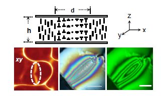
Figure 5.9. (Top) Schematic of a pure twist Bloch wall of width d. (Bottom) (left) A confocal image of a Bloch wall (dotted ellipse), and crossed polarized light images of a Bloch wall with (middle) white and (right) monochromatic illumination
The color sequence follows the Michel–Levy birefringence chart from either edge of the wall to the central plane. When a monochromatic light source is used, the wall between crossed polarizers shows interference fringes parallel to the wall. Should the Bloch walls be long enough, it is often observed that the wall is composed of two different handednesses, separated by what is referred to as a Neél wall, that mediates the difference in the two distinct handednesses of the Bloch walls, as illustrated in Figure 5.10. These structures are often not considered as spontaneous emergence of chiral structures, but, in fact, these are clear examples of the emergence of a chiral structure from an otherwise achiral system.
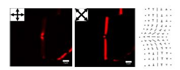
Figure 5.10. POM images of Bloch walls of two handednesses, mediated by a Neel wall, along with schematic of the director configuration of a Neel wall
5.2.4. Spontaneous emergence of chirality due to confinement
It is often convenient to study LCs in flat geometries, as it allows for easy manipulation of the director and the measurement of many characteristic properties using simple experiments. However, the confinement of LCs to curved geometry results in a much richer phenomenology. Curvature induces deformation of the director that costs energy. The terms describing the free energy of LCs are all of the order (∇n)2 to leading order. For this reason, Frank (1958), in his original description, uses the term “curvature elasticity” to describe the nematic elasticity. The presence of curvature can also result in competing effects of surface and bulk elastic constants which result in several interesting director configurations. The richness is further enhanced if the nematic fluid has significant anisotropy of its elastic constants, as is often the case with lyotropic nematic LCs. In this section, we discuss the spontaneous emergence of chiral structures from a class of LCs referred to lyotropic chromonic liquid crystals (LCLCs), as well as some lyotropic polymeric LCs.
LCLCs have gained increasing attention in the last two decades as an interesting but still poorly understood class of lyotropic LCs (Attwood et al. 1986; Vasilevskaya et al. 1989; Lydon 1998a, 1998b, 2004). LCLCs consist of many dyes, drugs, nucleic acids, antibiotics and anti-cancer agents (Cox et al. 1971; Hartshorne and Woodard, 1973; Attwood et al. 1986; Vasilevskaya et al. 1989; Lydon 1998a, 1998b, 2004; Horowitz et al. 2005; Park et al. 2008). The main structural feature of the molecules that comprise a chromonic liquid crystalline phase is either a disk-like or plank-like rigid aromatic core surrounded by either ionic or hydrogen-bonding groups (Lydon 1998b). When these molecules are dissolved in water, they stack against each other into rod-like aggregates with polydisperse lengths, even at very low concentrations (Attwood et al. 1986; Vasilevskaya et al. 1989; Lydon 1998b, 2004). The π-π interactions among the molecules are thought to be the driving force for the aggregation of these molecules into rod-like shapes.
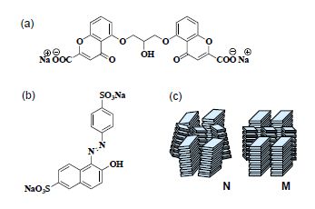
Figure 5.11. Molecular structures of (a) DSCG (disodium chromoglycate) and (b) (sunset yellow (SSY) FCF). (c) Schematic of two chromonic mesophases: nematic N and hexagonal (or columnar) M phases. (c) is redrawn after Lydon (1998b)
As the concentration reaches about 5–30 wt% of the dye in solution, a liquid crystalline phase forms (Attwood et al. 1986; Vasilevskaya et al. 1989; Lydon 1998b, 2004). There are two principal, well-characterized chromonic mesophases: a nematic N phase and a hexagonal M phase, as illustrated in Figure 5.11. The M phase is a fairly concentrated phase with a hexagonal array of molecular stacks, also referred to as the columnar phase.
In the recent past, the study of LCLCs has led to a number of observations that have been quite surprising and unexpected, and has inspired re-examination of a number of studies dealing with nematic LCs. We will start our description of them with a rather intriguing list of new observations that lead to the emergence of chiral structures from achiral systems which are quite exciting, and illustrate the rich phenomenology arising, primarily, from the fact that these materials posses anisotropic elastic properties, coupled with confinement to curved geometries.
As early as 1949, Onsager (1949) pointed out that a rod-like object in solution can form an ordered state, the so-called nematic phase (N), where the rods are parallel to each other, when their concentration exceeded some critical value.
Tobacco Mosaic Virus (TMV) is a rod-like particle with a length of 3,000 Å and 180 Å in diameter, and is monodisperse. Monodisperse aqueous solutions of TMV form a nematic phase between the concentrations of 30 and 70 mg/ml in pure water. Onsager provided an explanation for the obersvations of Bawden, Pirie, Bernal and Fankuchen (Bawden et al. 1936), dealing with aqueous suspensions of TMV that phase separated into an isotropic phase (I) and a nematic phase (N). It should be noted that the N-phase emerges as spindle-like objects called “tactoids”, and such N-tactoids have been shown to exist for a number of other materials. In these earlier studies, there was no mention of chirality in the tactoids, although it might seem prudent to re-examine these systems in light of things that are discussed in the following pages.
Recently, Tortora and Lavrentovich (2011), when studying solutions of disodium chromoglycate (DSCG, see Figure 5.11(a) for the chemical structure) in water with a finite concentration of polyethylene glycol (PEG), observed tactoids that displayed “chiral symmetry breaking”, meaning that the tactoids displayed both left-handed and right-handed twist structures, as illustrated in Figure 5.12. As already noted above, one should not use the term “chiral symmetry breaking” for these situations.
Figure 5.13 illustrates a chiral tactoid that was observed by Srinivasarao (Srinivasarao and Berry 1992) during the preparation of monodomains of a polymeric nematic in solution, but, at that time, was not recognized for the spontaneous emergence of chirality. This appears to be the first observation of the emergence of chiral structures from an achiral nematic solution. Incidentally, such polymeric nematics have a large anisotropy in their elastic constants, with twist elastic constant being at least an order of magniture lower than either splay or bend (Desvignes et al. 1993).

Figure 5.12. Nematic tactoids in the biphasic N-Iso sample of a lyotropic chromonic liquid crystal formed by aqueous dispersion of disodium cromoglycate. (a) Polarizing microscopy texture of an achiral tactoid and (b) the corresponding director structure; (c) and (d) the same for a twisted director structure. The system contains no chiral additives (see Tortora and Lavrentovich (2011) for details)
The rationale for the emergence of chiral structures in these tactoids is that the twist deformation replaces the energetically costly splay packing of the aggregates within the curved bipolar tactoids. This provides a simple prescription for creating chiral structures: that the material has a certain anisotropy of the elastic properties and that it has non-flat confinement!
It is well known that nematic LCs, when confined to spherical droplets with planar anchroing, form what are known as bipolar droplets with a point defect at the poles of the sphere. In their studies dealing with droplets of LCLCs, Yodh and co-workers (Jeong et al. 2014) used solutions of Sunset Yellow (SSY) in water and found that the droplets have a twisted bipolar structure, a consequence of a very low twist elastic constant. This leads to a very large twist in the droplets, despite the lack of chirality in the system, and are similar to those observed when the droplets are made with LCs possessing intrinsic chirality.

Figure 5.13. Chemical structure of poly(benzlbisthiazole) (PBZT) and polarized optical image of a tactoid formed from PBZT solutions in methane sulfonic acid
5.2.5. Spontaneous emergence of chirality due to cylindrical confinement
5.2.5.1. Director normal to the surfaces
In 1973, R.B. Meyer (Meyer 1973; de Gennes 1974) and Williams, Pieranski and Cladis (Williams et al. 1972) demonstrated that when a nematic fluid is confined to a cylindrical capillary, where the director is normal everywhere on the capillary surface, the director (n) escapes along the length of the capillary, therefore leading to a continous structure (plus a few point defects) and thus avoiding having a line defect throughout the capillary. This has been referred to as “escape in the third dimension” (or sometimes as an escaped radial) and has been experimentally verified over the course of five decades for many thermotropic LCs. Figure 5.14 illustrates such a situation where a well-known and well-studied thermotropic nematic LC, 5CB, is confined to a cylinder with homeotropic boundary conditions. We can clearly see the continous structure under crossed polarizers and a schematic of the director configuration is also shown in the figure. When such experiments are done with LCLCs the results are quite strikingly different with a new ground state.
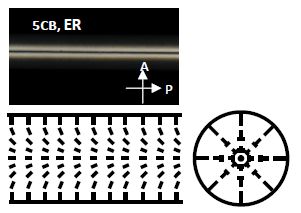
Figure 5.14. POM image of the ER in a cylindrical capillary filled with 5CB, and schematics of the director configuration
Jeong et al. (2015) reported on such an experiment where the SSY solutions were confined to a cylindrical capillary with homeotropic boundary conditions. The initial configuration of the director was the well-known escape in the third dimension. However, this configuration quickly turned into a twisted configuration where the splay and bend deformations in the capillary were replaced by a twist (due to the low twist elastic constant). This results in a twisted and escaped radial configuration (referred to as TER, see Figure 5.15), where the nematic director is parallel to the cylindrical axis near the center; but to possess the homeotropic boundary condition near the capillary wall, the director escapes along the radius through bend and twist distrotions. This also leads to a panopoly of defects that will not be described in detail here, but has been discussed by Jeong et al. (2015). This TER structure is eventually replaced by a set of two singular lines forming a double helix (as shown in Figure 5.16) which remians stable for an extended period of time. It would appear that this structure, with two singular lines forming the double helix, is the new ground state for these lyotropic materials confined to a cylinder with homeotropic boundary conditions.

Figure 5.15. POM image of the twisted escaped radial texture (TER) in a cylindrical capillary for DSCG and SSY solutions in water, along with schematics of the director configuration
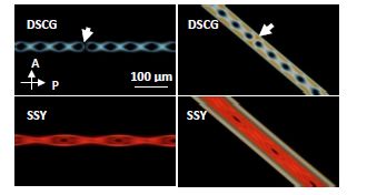
Figure 5.16. Formation of the double helix from the TER structure. The white arrow in DSCG point to walls in the structure. Each image has the same polarizer directions and magnification
It appears that this report of a TER structure eventually leading to two line defects forming a double helical structure down the long axis of the cylinder, reported by Jeong et al., is not the first of its kind. Such a structure was reported by Jin-Hua Wang (1996), a student of R.B. Meyer. Wang observed such a structure in solutions of TMV in capillaries with homeotropic alignment, as early as 1996. That TMV forms a liquid crystalline phase was known as early as 1936, and led to the formulation of a theory for the phase separation by Lars Onsager in 1949, as noted above. In the experiments of Wang, TMV solutions in the nematic phase were confined to cylindrical capillaries with homeotropic boundary conditions. Wang also noted that the two bright “spiral lines” running through the entire length of the capillary were “clearly visible even without a microscope”. It was also noted that the lines did not lie on the surface of the quartz capillary, and that they were at a distance of 35 μm from the capillary walls. These observations are strikingly similar to those reported by Jeong et al. (2015), but for a system that is polymeric in nature.
It should be mentioned that we have used another polymeric nematic material, poly benzyl glutamate with homeotropic boundary conditions, and the observations mimic what has been seen for LCLCs, TMV and also some micellar nematics (Dietrich et al. 2017). It appears that the observations described thus far, that the escape in the third dimension giving rise to a TER configuration, followed by the transformation of the TER to a system with two spiraling line defects down the length of the capillary, seems to be common for all nematic fluids that are lyotropic in nature, as most if not all have a very low twist elastic constant (Dietrich et al. 2020).
The presence of TER structures can be rationalized on the basis of a low twist elastic constant for this class of LCs. The free energy cost of splay, twist, bend and saddle-splay distortions of a nematic fluid is described by the well-known Frank-Oseen elastic free energy:
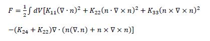
Jeong et al. (2015) performed numerical calculations to understand the rationale for the observation of TER structures using the known values for lyotropic LCs (Zhou et al. 2012). From their calculations they came to the conclusion that the TER director configuration lowers the elastic free energies of the “escape in the third dimension” or the escaped radial configuration, with a degenerate twist deformation, the twist being either left- or right-handed. They noted that total elastic free energy of the twisted (TER) configuration is smaller than that of the escaped radial configuration when K22< K22~0.27K, where K = K11=K33. So, the condition for observing a twisted structure in lieu of the escaped radial structure is that when the twist elastic constant is about an order of magnitude smaller than the corresponding splay and bend elastic constants, a condition that many lyotropic LCs satisfy. It should be noted, for cylinders with homeotropic boundary conditions, where ![]() is normal to the boundaries of the cylinder, the saddle-splay (K24) contribution to the total free energy takes on a constant value, and does not depend on what
is normal to the boundaries of the cylinder, the saddle-splay (K24) contribution to the total free energy takes on a constant value, and does not depend on what ![]() is in the bulk, and hence does not play a major role in determining the director configuration.
is in the bulk, and hence does not play a major role in determining the director configuration.
5.2.5.2. Director parallel to the surfaces
Now we consider the case of confining lyotropic nematics in a cylinder with planar degenerated (gliding) boundary conditions. As already indicated, when nematic LCs are confined within flat boundaries with planar boundary conditions, the ground state is characterized by an average molecular orientation along a common direction referred to as the easy axis of the director, denoted by n. Curvature for nematics costs energy and the coupling of the curvature with the free energy can be appreciated when one notes that the elastic free energy expression of the n is of the order of (∇n)2. For this reason, the Frank free energy is often referred to as the curvature elasticity of nematic LCs (Frank 1958). Pairam et al. (2013) confined prototypical nematics, the thermotropic NLC 4-Cyano-4’-pentylbiphenyl (5CB), in a toroid with the director parallel to the surfaces everywhere, and demonstrated that the, achiral, axial state is unstable to the doubly twisted, chiral state that depended both on K22/K24 and the aspect ratio of the torus ξ =R0/ a, where R0 is the central ring radius and a the tube radius. They also demonstrated that the magnitude of the twist distortion in a toroid grew with decreasing aspect ratio due, in large part, to the K24 contributions to the overall free energy of the system, thus effectively screening the energy penalty of an increasing twist distrotion.

Figure 5.17. Schematic of the director configuration of (a) axial and (b) double twist
We now confine the LCLCs in a cylinder with planar boundary conditions and interrogate the resulting director configuration. In most experiments with conventional nematics, the director lies along the long axis of the capillary, the axial configuration, as illustrated in Figure 5.17(a). When such a configuration is observed under crossed polarizers, the intensity profile of the transmitted light beam is of the form: ![]() where ∅p is the angle between the easy axis of the polarizer and the director. The observed intensity is a minimum when the director is either parallel or perpendicular to the incident polarization, leading to complete extinction of the light, with the maximum intensity being at an angle of 45° with respect to the incident polarization. This is exactly what is observed when one confines a thermotropic LC, say 5CB for example, with planar boundary conditions.
where ∅p is the angle between the easy axis of the polarizer and the director. The observed intensity is a minimum when the director is either parallel or perpendicular to the incident polarization, leading to complete extinction of the light, with the maximum intensity being at an angle of 45° with respect to the incident polarization. This is exactly what is observed when one confines a thermotropic LC, say 5CB for example, with planar boundary conditions.
However, when the experiments are repeated with solutions of DSCG, the observations point to a different result. Images under a polarized light microscope for two angular positions of a capillary filled with DSCG solutions are shown in Figure 5.18(a) and 5.18(b), corresponding to the long axis of the capillary being parallel and at 45° with respect to the incident polarization, respectively. It is quite clear in both cases that the expected extinction of the incident light is not achieved. Should one have an axial configuration, the image corresponding to Figure 5.18(a) would be one of complete extinction of light. Instead, incident light is transmitted by propagating through the sample and they appear to possess comparable intensities in both Figure 5.18(a) and Figure 5.18(b). This simple observation makes it abundantly clear that the plane of polarization of the linearly polarized incident light is rotated by the lyotropic LC, DSCG, and exits at an angle to the analyzer that is neither 0° nor 90°. As already noted above when dealing with Pasteur’s discovery of optical activity, this represents a classic signature of twists. A doubly twisted configuration would explain the observed images and is illustrated in Figure 5.17(b). The director of this doubly twisted configuration is axial at the center of the cylinder, twisting progressively as it approaches the surface.
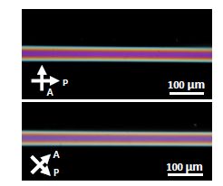
Figure 5.18. Crossed polarized microscopic images of DSCG in a cylindrical capillary
Validation of the hypothesis of a double twist can be done by carrying out Jones matrix simulation with a simple doubly twisted director ansatz, as such simulations quantify the change in the polarization state of the light as it traverses the sample. The doubly twisted director is specified by ![]() ez are the orthonormal vectors in cylindrical coordinates, with
ez are the orthonormal vectors in cylindrical coordinates, with ![]()
![]() The twist parameter ω determines the amount of twist in the system; ω = 0 corresponds to an axial configuration, r is the radial distance from the center of the circular cross-section and R is the cylinder radius. The simulated optical microscopy textures conform closely to the experimental observations that light is indeed not extinguished with the capillary long-axis parallel to the polarization, of the incident polarization as well as reproducing all the aspects of the measured intensity profiles. These lend credibility to the idea that we must, indeed, have a doubly twisted director configuration in a cylindrical capillary.
The twist parameter ω determines the amount of twist in the system; ω = 0 corresponds to an axial configuration, r is the radial distance from the center of the circular cross-section and R is the cylinder radius. The simulated optical microscopy textures conform closely to the experimental observations that light is indeed not extinguished with the capillary long-axis parallel to the polarization, of the incident polarization as well as reproducing all the aspects of the measured intensity profiles. These lend credibility to the idea that we must, indeed, have a doubly twisted director configuration in a cylindrical capillary.
Based on the experimental observations and the Jones matrix simulations, we can then ask a number of questions that are of consequence: What drives the spontaneous twist deformation of the director field? How twisted is the structure of the double twist? Is there a size dependence of this twist? All of these questions are addressed in detail elsewhere (Davidson et al. 2015; Nayani et al. 2015), but we provide the essential arguments below.
In order to understand the driving force for the doubly twisted configuration, we start by considering the contribution of the saddle-splay (K24) term in the free energy expression given by equation [5.1], where K11, K22 and K33 are the Frank elastic constants associated with splay, twist and bend bulk deformations. We ignore the splay-bend (K13) contribution as we are dealing with a case of planar anchoring, though the influence of K13 has been quite contentious (Lavrentovich and Pergramenshchik 1995). It should also be noted that several studies have neglected the contribution of saddle-splay under strong anchoring conditions, the rationale for which stems from the fact that the bulk integral of the saddle-splay can be reduced to a surface integral using Stoke’s theorem, and that the contribution of saddle-splay on the surface would be negligible in comparison to the cost of the anchoring violation. However, this argument is troublesome as the saddle-splay contribution can only be neglected if the director depends only on one Cartesian coordinate, and for strong anchoring, which is not the case in the experiments described (Kralj and Zumer 1995). For planar anchoring, when the confining boundaries are curved, the contribution of K24 cannot be neglected, which would indicate that planar anchoring may lay at an angle to the confining cylinder long-axis. Further, in geometries like cylinders where the two principal curvatures are different, the contribution of saddle splay plays a prominent role in determining the director configuration.
For the case of planar anchoring, the saddle-splay term can align the director along the direction of the largest principal curvature. To better understand this, the K24 contribution to the free energy (per unit length) can be written as: ![]()
![]() where k1 and k2 are the principal curvatures at a point on the surface and n1 and n2 are the director components along the corresponding directions. For a cylinder, n1 = nθ and n2 = nz hence, k1 = 1/R and k2 = 0. As a result, for the case of cylindrical geometry, the integral of F24 is minimized when the director at the surface is along the eθ direction, thus driving the system to twist and provided that there is sufficient anisotropy of the elastic constants, the twisted structure is always stable.
where k1 and k2 are the principal curvatures at a point on the surface and n1 and n2 are the director components along the corresponding directions. For a cylinder, n1 = nθ and n2 = nz hence, k1 = 1/R and k2 = 0. As a result, for the case of cylindrical geometry, the integral of F24 is minimized when the director at the surface is along the eθ direction, thus driving the system to twist and provided that there is sufficient anisotropy of the elastic constants, the twisted structure is always stable.
Using the same director ansatz outlined for the Jones matrix simulation, we obtain an expression in leading order of ω for the free energy per unit length:

It is, in fact, the sign of the quadratic term that determines whether the system adopts an axial configuration or breaks reflection symmetry, resulting in a chiral, doubly twisted director configuration. This theory is generic and would describe the reflection symmetry breaking of any nematic fluid. Provided K24 > K22, the director is always going to be twisted. Specifically, for LCLCs the low value of K22 almost always leads to the possibility of satisfying the twisting criterion. From the observation of twisted director configurations, it is self-evident that K24 for LCLCs studied must always be greater than K22. While the model is relatively simplistic (in terms of the ansatz used), the essential physics is captured with the criterion that K24 > K22 for a twisted structure.
For ascertaining the criterion for the twist, we can calculate the value of K24 by comparing the value of the twist parameter ω measured experimentally, and that obtained after minimizing the free energy expression with the experimental measurement of ![]() with ω The twist parameter is obtained by measuring the twist angle as the beam traverses the diameter of the cylinder. In order to do this, we used the Mauguin limit, where
with ω The twist parameter is obtained by measuring the twist angle as the beam traverses the diameter of the cylinder. In order to do this, we used the Mauguin limit, where ![]() , with ∅ the total twist angle and Γ the retardation due to the anisotropy of the refractive indices, and the director field serves as a waveguide to the incident polarized light. Due to the low birefringence, ne – no, (~0.02) for DSCG, capillaries of diameter 400 µm are necessary to satisfy the waveguiding requirement. Using waveguiding measurements, we estimate the total twist angle for the solutions used in the study to be (150 ± 10)o.
, with ∅ the total twist angle and Γ the retardation due to the anisotropy of the refractive indices, and the director field serves as a waveguide to the incident polarized light. Due to the low birefringence, ne – no, (~0.02) for DSCG, capillaries of diameter 400 µm are necessary to satisfy the waveguiding requirement. Using waveguiding measurements, we estimate the total twist angle for the solutions used in the study to be (150 ± 10)o.
In the ansatz chosen, ∅ = 2 sin-1(ω), we find that ω = 0.95 ± 0.03. Substituting the value of ω thus determined into the theoretical expression below:
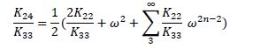
we find that the range of K24/K33 for DSCG varies from 0.75 to 1.75 under the assumption that K22/K33 ~ 0.1. We performed the same experiment with SSY to obtain a twist angle close to 170o. This would correspond to a value of K24/K33 of 6.75. It should, however, be noted that the exact value of K24/K33 is extremely sensitive to the value of the twist angle for large twists (ω ~ 1). By way of comparison to small molecule LCs, say 5CB, we note that the value of K24 is significantly higher in comparison to the other elastic constants. For all the capillary dimensions (50, 100, 400 and 500 µm) used in the experiments, the twist angle measured is independent of the system size, pointing to another interesting aspect of the results thus far. This is in contrast to measurements made by Pasteur where the specific rotation [α],
was +12° for tartaric acid, where α (in degrees) is the observed optical rotation, l is the length of the sample tube (in decimeters) and c is the concentration (in gm/ml) of the solution.
Since the twist angle is independent of the system size, we can confine LCLCs in as small a capillary as experimentally possible and still obtain the same values of the twist angle. It should be noted that the twist angle depends only on the ratio of the elastic constants. It should also be evident that the obtained values of K24/K33 seemingly violate Ericksen’s inequalities (Ericksen 1966); these emerge on the basis that the Frank free energy is positive definite, with the minimum being assumed to be a deformation free director. In the systems chosen for the experiments, the anisotropy of the elastic constants results in the formation of a ground state that is lower in energy than the deformation free ground state. Therefore, we conclude that Ericksen’s inequalities no longer apply. In a recent paper, Selinger considers the role of K24, providing a nice discussion of its implications on various experimental observations (Selinger 2018), while also noting the circular nature of the argument leading to Ericksen’s inequalities.
In prior studies, we have formed monodomains of LCLCs using a rectangular capillary but had noticed the presence of two line defects confined to the edges of the capillary. We have also previously studied the dynamics of such line defects that were formed in the capillary (Shams et al. 2015); however, we had not paid enough attention to the pathway of the LC to the monodomain state. In an attempt to understand the pathway to a monodomain, we re-evaluate the experiments in rectangular capillaries (Fu et al. 2017). When LCLC is confined to a rectangular capillary with planar boundary conditions, one expects an axial director profile pointing along the long axis of the capillary, corresponding to a deformation free ground state. As already discussed, for such a director configuration one expects complete extinction of light when the capillary is either parallel or perpendicular to the polarizers. However, when a sample is cooled from the isotropic to the nematic phase, we find that light is transmitted even when the capillary is parallel to the polarizer, as shown in Figure 5.19(a). Such an observation implies that the director is twisted. It is also evident that there are disclination lines that separate different domains; these are in fact domains of opposite twists as can be seen from uncrossing the polarizers, where in Figure 5.19(b) and Figure 5.19(c) correspond to images with polarizers making an angle of 70° and 110° with each other. Figure 5.19(d) is a schematic illustration of the doubly twisted director profile that would be consistent with the experimental results.
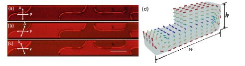
Figure 5.19. Crossed polarized microscopic images of DSCG in a cylindrical capillary. Reprinted with permission from Fu et al. (2017)
On cooling the sample from the isotropic phase, it is seen that the twist, in fact, originates at the edges of the capillary (Figure 5.20(a)) with the twisted fronts approaching each other as they engulf the isotropic regions (Figure 5.20(b–e)). The twisted domains are spatially random with equal probability for either handedness. When the two twisted domains meet, those with the same handedness merge, while those with opposite handedness are separated by disclination lines.
We can use rather simplistic scaling arguments for the preference of a doubly twisted director configuration as opposed to the axial configuration. Let us start with the assumption that the rectangular capillary can be treated as a pair of flat plates capped with semi-cylindrical edges. In this case, it is evident that the director would favor a doubly twisted profile driven by K24, as was the case for a cylinder. For a twist angle close to 180°, the K24 contribution to the free energy per until length would be –πK24. While twist is favorable at the edges, the twist in the flat region of the capillary results in an energy penalty estimated as K22 (w/h) (~10K22, for the geometry used), where w is the width of the rectangle and h is the height between the plates. The energy cost for having a doubly twisted director (FDT) for a rectangular capillary is FDT ~ (10K22−πK24), and K24 for SSY is about 50K22, implying FDT < 0, and hence a doubly twisted configuration is favored in the rectangular capillary.
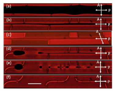
Figure 5.20. Time lapsed POM images of SSY cooling down from isotropic phase to nematic phase. The twist region of random handedness nucleates at the edges, expands to the entire capillary. Polarizer and analyzer are crossed in (a)(b) and (d)(e)(f), but uncrossed in (c). Scale bar is 200 μm. Reprinted with permission from Fu et al. (2017)
Although it is favorable to twist at the edges, twisting in the flat region costs energy. A simple scaling argument would estimate the energy cost per unit length in the flat region to be of the order K22 (w/h) (~10K22, for our geometry), where w is the width of the rectangle and h is the height, as shown in Figure 5.20d. Hence, the deformation cost of having a doubly twisted director (FDT) in a rectangular capillary is: FDT ~ (10K22−πK24). Previous experimental estimates of K24 for SSY are about the order 50K22 (Davidson et al. 2015; Nayani et al. 2015). Clearly this implies, FDT<0, and the doubly twisted director is preferable when compared to axial configuration (Faxial=0). This explains the initial doubly twisted director configuration in the rectangular capillary. However, in a few hours the doubly twisted configuration leads to a monodomain in the flat regions of the capillary but with the twist confined to the edges, mediated by two line defects that separate the twisted and the axial configuration. It should be noted that the defect lines are in the midplane running along the entire length of the capillary, and the twist being confined to the hemispherical caps of the capillary.
The monodomain configuration in the flat region does not suffer any energy penalty; however, there is a penalty to be paid for the two half-strength disclination lines. A simple estimate of the energy cost of the disclination core per unit length is of the order of πKm, where m = 1/2 is the strength of the line. Since twists are the dominant deformation around the core, the energy cost for the two lines is π(K22/2). Clearly, the cost of having two disclination lines is an order of magnitude lower than the doubly twisted flat regions, and the monodomain-like configuration is stable for months and is likely the ground state for SSY in rectangular capillaries.
In an effort to ascertain the above analysis, experiments were done with square capillaries with widths of 50 and 100 μm. In this case, one does form the doubly twisted configuration and this remains stable for months without ever reverting to a monodomain, as in the case of a rectangular capillary. Again, using the previous scaling arguments, we note FDT ~ (K22 (w/h) − πK24) for a doubly twisted configuration; and FMono ~ (π(K22/2) − πK24) for a monodomain-like configuration in a rectangular capillary. For a square capillary, w/h is 1, such that FDT is smaller than FMono, thus leading to the conclusion that the doubly twisted configuration is the desired one for SSY in a square capillary.
5.2.6. Some misconceptions about optical rotation
Having discussed the spontaneous emergence of chirality or chiral structures in the previous sections, dealing primarily with ordered nematic fluids, to conclude this chapter, we now turn our attention to a common misconception about optical rotation and its link to molecular chirality; thus reconnecting back to the historical beginnings outlined in this chapter.
Chemistry students know that the presence of optical activity implies a chiral, or dissymmetric, arrangement, the appreciation of this fact was possible only after many years of painstaking work by some of the most noted scientists of the 19th century, as discussed in section 5.2.2. Perhaps the first exposure of a chemistry student to the rotation of the plane of polarization of a linearly polarized light beam is often in introductory courses dealing with organic chemistry. One is taught in such courses, that the observation of optical rotation is a confirmation of chirality of molecules in isotropic liquids. Often a corollary of this lesson is that enantiomorphism is a necessary condition for optical rotation. As Kahr notes in his minireview on “Optical rotation of achiral compounds” (Claborn et al. 2008), a premier textbook in organic chemistry states that “the same non-superimposability of mirror images that gives rise to enantiomerism is also responsible for optical activity” (Boyd and Morrison 1976). With a sense of frustration, Kahr notes, “Unfortunately, the link between optical activity and enantiomorphism is not only introduced early and reinforced relentlessly in a chemist’s education, it is wrong”. It has been pointed out quite elegantly by Barron (2009), O’Loane (1980) and Nye (1985), among others, that oriented systems belonging to non-enatiomorphous point groups will show optical rotation or be optically active for certain directions of the incident light; however, this fact has not made significant inroads in the science of molecular chirality.
The term nonenantiomorphous refers to crystals that can be superposed on to their mirror image. From his experiments Pasteur concluded that enantiomorphism is a necessary condition for optical activity or optical rotation in crystals, an erroneous conclusion to be sure. In 1882, J. Willard Gibbs, in a paper entitled, “Double refraction in perfectly transparent media which exhibit the phenomena of circular polarization”, in the American Journal of Science – utilizing Maxwell’s electromagnetic theory – proposed that crystals belonging to two non-enatiomorphous point groups [S4(4) and D2d- (42m)] could be optically active and rotate the plane of polarized light. In a footnote, Gibbs imagines crystals composed of spiral forms and writes:
There is no difficulty in conceiving of the constitution of a body which would have the properties described above. Thus, we may imagine a body with molecules of a spiral form, of which one half are right-handed and one half left-handed, and we may suppose that the motion of electricity is opposed by a less resistance within them than without. If the axes of the right-handed molecules are parallel to the axis of X, and those of the left-handed molecules to the axis of Y, their effects would counterbalance one another when the wave-normal is parallel to the axis of Z. But when the wave-normal (of a beam of polarized light) is parallel to the axis of X, the left-handed molecules would produce a left-handed (negative) rotation of the plane of polarization, the right-handed molecules having no effect; and when the wave-normal is parallel to the axis of Y, the reverse would be the case.
This implies that an incident light beam might encounter paths with differing optical activity along different directions, within a given material. Validation of the Gibbs conjecture had to wait for about 85 years until Hobden (1967) was able to measure optical activity in two nonenatiomorphous crystals – silver gallium sulfide belonging to point group D2d (42 m), and cadmium gallium sulfide – of point group S4(4), and these measurements made possible by the material becoming fortuitously isotropic for light at a wavelength of 487.2 nm. With these measurements, Hobden wrote in 1967, “It is hoped that this observation will finally eradicate the notion that optical activity is exclusively related to enatiomorphism”. It is our hope that the above discussion rights some of the misconceptions about optical activity in various materials.
5.3. Concluding remarks
The Nobel Prize winning chemist Vladimir Prelog commented that, “The world is chiral and clinal, enjoy symmetry wherever you find it”, and, in keeping with the beauty implied by this statement, this work has tried to provide a curated tour of chirality in ordered achiral fluids. Namely, a tour confined to the spontaneous emergence of chiral structures is presented when ordered fluids, that are themselves achiral, are confined within curved surfaces. It is remarkable to find the various conditions under which large-scale chiral structures emerge. For the materials that have been considered here, it appears that emergent chiral structures are driven by the achiral material’s large anisotropy in their elastic constants in response to the imposed boundary conditions. In particular, having a low twist elastic constant relative to the other elastic constants seems to be a key element for the emergence of chiral structures. The main takeaways of this chapter are an attempt to clarify the misuse of the term “chiral symmetry breaking”, as well as providing a tour of the remarkable progress that has been made over the past two centuries, albeit an incomplete tour. Clearly, no attempt has been made to be comprehensive, but rather a conscience choice was made to provide a flavor of interesting phenomena that lead to the emergence of chiral structures in a class of LCs, known as LCLCs, that exhibits the apparently necessary anisotropy of its elastic constants, and when confined with the appropriate boundary conditions. In one sense, the clarification and perspective presented in this chapter demote such spontaneous chiral structures; they are seen as not a true phase transition of the LCLC and hence are inappropriate to use symmetry breaking concepts. However, in another sense, these beautiful emergent structures stemming from the delicate interplay of material properties, surface anchoring and boundary conditions exemplify the rich and surprising phenomena inherent in LCs and those yet to be explored.
5.4. Acknowledgments
It is a pleasure to acknowledge several illuminating discussions with Prof. Bart Kahr of NYU, Prof. Germano Iannacchione of WPI, Prof. Peter Collings of Swarthmore College, Prof. Dilip Kondepudi of Wake Forest University and Prof. Pawel Pieranski of Université Paris-Sud. It is with pleasure that I thank Oleg Lavrentovich for providing me the images used in Figure 5.12. It is a pleasure to acknowledge various discussions and help with the manuscript from Dr. Jung Ok Park. It is a pleasure to thank my former students, Dr. Xuxia Yao, Dr. Karthik Nayani and Dr. Rui Chang, whose work forms the basis of this chapter. The author declares no competing financial interests.
5.5. References
Amundson, K.R. and Srinivasarao, M. (1998). Liquid-crystal-anchoring transitions at surfaces created by polymerization-induced phase separation. Physical Review E, 58(2), R1211–R1214.
Applequist, J. (1987). Optical activity: Biot’s bequest. American Scientist, 75(1), 59–68. Arago, F. (1859). Biographies of Distinguished Scientific Men. Ticknor and Fields, Boston. Attwood, T.K., Lydon, J.E., Jones, F. (1986). The chromonic phases of dyes. Liquid Crystals, 1(6), 499–507.
Ávalos, M.N., Babiano, R., Cintas, P., Jiménez, J.L., Palacios, J.C. (2004). Symmetry breaking: An epistemological note. Tetrahedron: Asymmetry, 15(20), 3171–3175.
Ball, P. (2005). Elegant Solutions: Ten Beautiful Experiments in Chemistry. The Royal Society of Chemistry, Cambridge.
Barron, L.D. (2009). An introduction to chirality at the nanoscale. In Chirality at the Nanoscale – Nanoparticles, Surfaces, Materials and More, Amabilino, D.B. (ed.). Wiley-VCH, Weinheim.
Bawden, F.C., Pirie, N.W., Bernal, J.D., Fankuchen, I. (1936). Liquid crystalline substances from virus-infected plants. Nature, 138, 1051–1052.
Boyd, R.N. and Morrison, R.T. (1976). Organic Chemistry, 2nd edition. Prentice Hall, New Jersey.
Claborn, K., Isborn, C., Kaminsky, W., Kahr, B. (2008). Optical rotation of achiral compounds. Angewandte Chemie – International Edition, 47(31), 5706–5717.
Cox, J.S.G., Woodard, G.D., Mccrone, W.C. (1971). Solid-state chemistry of cromolyn sodium (disodium-cromoglycate). Journal of Pharmaceutical Sciences, 60(10), 1458–1465.
Davidson, Z.S., Kang, L., Jeong, J., Still, T., Collings, P.J., Lubensky, T.C., Yodh, A.G. (2015). Chiral structures and defects of lyotropic chromonic liquid crystals induced by saddle-splay elasticity. Physical Review E, 91(5), 050501(R).
Desvignes, N., Suresh, K.A., Berry, G.C. (1993). Static and dynamic light-scattering on aligned solutions of a rodlike polymer, polymer analysis and characterization. J. Applied Polymer Symposia Series, 52, 33–43.
Dietrich, C.F., Rudquist, P., Lorenz, K., Giesselmann, F. (2017). Chiral structures from achiral micellar lyotropic liquid crystals under capillary confinement. Langmuir, 33(23), 5852–5862.
Dietrich, C.F., Collings, P.J., Sottmann, T., Rudquist, P., Giesselmann, F. (2020). Extremely small twist elastic constants in lyotropic nematic liquid crystals. Proceedings of the National Academy of Sciences of the United States of America, 117(44), 27238–27244.
Ericksen, J.L. (1966). Inequalities in liquid crystal theory. Physics of Fluids, 9(6), 1205–1207. Frank, F.C. (1958). I. Liquid crystals. On the theory of liquid crystals. Discussions of the Faraday Society, 25, 19–28.
Freemantle, M. (2003). Chemistry at its most beautiful. Chemical & Engineering News, 81(34), 27–30.
Fu, J.X., Nayani, K., Park, J.O., Srinivasarao, M. (2017). Spontaneous emergence of twist and the formation of a monodomain in lyotropic chromonic liquid crystals confined to capillaries. NPG Asia Materials, 9, e393.
Gal, J. (2013). Molecular chirality in chemistry and biology: Historical milestones. Helvetica Chimica Acta, 96(9), 1617–1657.
de Gennes, P.G. (1974). The Physics of Liquid Crystals. Clarendon Press, London.
Ghosh, A. and Fischer, P. (2006). Chiral molecules split light: Reflection and refraction in a chiral liquid. Physical Review Letters, 97(17).
Guijarro, A. and Yus, M. (2009). The Origins of Chirality in the Molecules of Life. Royal Society of Chemistry, Cambridge.
Hartshorne, N.H. and Woodard, G.D. (1973). Mesomorphism in system disodium chromoglycate-water. Molecular Crystals and Liquid Crystals, 23(3–4), 343–368.
Helfrich, W. (1968). Alignment-inversion walls in nematic liquid crystals in the presence of a magnetic field. Phys. Rev. Lett., 21, 1518–1521.
Hobden, M.V. (1967). Optical activity in a non-enantiomorphous crystal silver gallium sulphide. Nature, 216(5116), 678.
Horowitz, V.R., Janowitz, L.A., Modic, A.L., Heiney, P.A., Collings, P.J. (2005). Aggregation behavior and chromonic liquid crystal properties of an anionic monoazo dye. Physical Review E, 72(4), 1710.
Jenkins F.A and White, H.E. (1981). Fundamentals of Optics. McGraw-Hill International Editions, London.
Jeong, J., Davidson, Z.S., Collings, P.J., Lubensky, T.C., Yodh, A.G. (2014). Chiral symmetry breaking and surface faceting in chromonic liquid crystal droplets with giant elastic anisotropy. Proceedings of the National Academy of Sciences of the United States of America, 111(5), 1742–1747.
Jeong, J., Kang, L., Davidson, Z.S., Collings, P.J., Lubensky, T.C., Yodh, A.G. (2015). Chiral structures from achiral liquid crystals in cylindrical capillaries. Proceedings of the National Academy of Sciences of the United States of America, 112(15), E1837–E1844.
Kahr, B. and Arteaga, O. (2012). Arago’s best paper. Chemphyschem, 13(1), 79–88.
Kant, I. (1991). On the first ground of the distinction of regions in space. In The Philosophy of Right and Left: Incongruent Counterparts and the Nature of Space, Van Cleve, J., Frederick, R.E. (eds). Kluwer Academic, Dordrecht.
Kleman, M. (1983). Points, Lines and Walls. John Wiley & Sons, New York.
Kralj, S. and Zumer, S. (1995). Saddle-splay elasticity of nematic structures confined to a cylindrical capillary. Physical Review E, 51(1), 366–379.
Krebs, H.A. (1970). History of tricarboxylic acid cycle. Perspectives in Biology and Medicine, 14(1), 154–172.
Lavrentovich, O.D. and Pergramenshchik, V.M. (1995). Patterns in thin liquid crystal films and the divergence (“surfacelike”) elasticity. International Journal of Modern Physics B, 09(18n19), 2389–2437.
Leger, L. (1973). Walls in nematics. Molecular Crystals and Liquid Crystals, 24(1–2), 33–44. Lowry, T.M. (1964). Optical Rotary Power. Dover Publications, New York.
Lydon, J. (1998a). Chromonic liquid crystal phases. Current Opinion in Colloid & Interface Science, 3(5), 458–466.
Lydon, J. (1998b). Chromonics. In Handbook of Liquid Crystals, Vol. 2B: Low Molecular Weight Liquid Crystals II, Demus, D., Goodby, J., Gray, G.W., Speiss, H.-W., Vill, V. (eds). Wiley-VCH, New York.
Lydon, J. (2004). Chromonic mesophases. Current Opinion in Colloid & Interface Science, 8(6), 480–490.
Mason, S.F. (1991). Chemical Evolution: Origins of the Elements, Molecules, and Living Systems. Clarendon Press, Oxford.
Meyer, R.B. (1973). Existence of even indexed disclinations in nematic liquid crystals. Philosophical Magazine, 27(2), 405–424.
Michelson, A.A. (1927). Studies in Optics. The University of Chicago Press, Chicago. Mislow, K. (2002). Introduction to Stereochemistry, Dover Publications, Mineola.
Nayani, K., Chang, R., Fu, J.X., Ellis, P.W., Fernandez-Nieves, A., Park, J.O., Srinivasarao, M. (2015). Spontaneous emergence of chirality in achiral lyotropic chromonic liquid crystals confined to cylinders. Nature Communications, 6, 8067.
Neville, A.C. and Caveney, S. (1969). Sacarabaeid beetle exocuticle as optical analogue of cholesteric liquid crystals. Biological Reviews of the Cambridge Philosophical Society, 44(4), 531–562.
Nye, J.F. (1985). Physical Properties of Crystals: Their Representation by Tensors and Matrices. Oxford University Press, Oxford.
O’Loane, J.K. (1980). Optical activity in small molecules, nonenantiomorphous crystals, and nematic liquid crystals. Chemical Reviews, 80(1), 41–61.
Onsager, L. (1949). The effects of shape on the interaction of colloidal particles. Annals of the New York Academy of Sciences, 51(4), 627–659.
Pairam, E., Vallamkondu, J., Koning, V., Van Zuiden, B.C., Ellis, P.W., Bates, M.A., Vitelli, V., Fernandez-Nieves, A. (2013). Stable nematic droplets with handles. Proceedings of the National Academy of Sciences of the United States of America, 110(23), 9295–9300.
Park, H.S., Kang, S.W., Tortora, L., Nastishin, Y., Finotello, D., Kumar, S., Lavrentovich, O.D. (2008). Self-assembly of lyotropic chromonic liquid crystal sunset yellow and effects of ionic additives. Journal of Physical Chemistry B, 112(51), 16307–16319.
Ramsay, O.B. (1981). Stereochemistry. Heyden, London.
Ryschenkow, G. and Kleman, M. (1976). Surface defects and structural transitions in very low anchoring energy nematic thin-films. Journal of Chemical Physics, 64(1), 404–412.
Selinger, J.V. (2018). Interpretation of saddle-splay and the Oseen-Frank free energy in liquid crystals. Liquid Crystals Reviews, 6(2), 129–142.
Shams, A., Yao, X., Park, J.O., Srinivasarao, M., Rey, A.D. (2015). Disclination elastica model of loop collision and growth in confined nematic liquid crystals. Soft Matter, 11(27), 5455–5464.
Srinivasarao, M. and Berry, G.C. (1992). Magnetic-field induced instability on an aligned nematic solution of a rodlike polymer. Molecular Crystals and Liquid Crystals, 223, 99–121.
Thomson, W. and Lord Kelvin, B. (1904). Baltimore Lectures on Molecular Dynamics and the Wave Theory of Light. C. J. Clay & Sons, London.
Tortora, L. and Lavrentovich, O.D. (2011). Chiral symmetry breaking by spatial confinement in tactoidal droplets of lyotropic chromonic liquid crystals. Proceedings of the National Academy of Sciences of the United States of America, 108(13), 5163–5168.
Vasilevskaya, A.S., Generalova, E.V., Sonin, A.S. (1989). Chromonic mesophases. Uspekhi Khimii, 58(9), 1575–1596.
Wagnière, G.H. (2007). On Chirality and the Universal Asymmetry: Reflections on Image and Mirror Image. Verlag Helvetica Chimica Acta, Zürich.
Walba, D.M. (2003). Ferroelectric liquid crystal conglomerates. In Topics in Stereochemistry, Materials-Chirality, Green, M.M., Nolte R.J.M,, Meijer, E.W., Denmark, S.E. (eds). John Wiley & Sons, New York.
Wald, G. (1957). The origin of optical activity. Annals of the New York Academy of Sciences, 69(2), 352–368.
Wang, J.-H. (1996). Liquid crystal phases formed by rod-like macromolecules. PhD Thesis, Brandeis University, Waltham, MA, USA.
Williams, C., Pieranski, P., Cladis, P.E. (1972). Nonsingular S=+1 screw disclination lines in nematics. Physical Review Letters, 29(2), 90–92.
Young, A.T. (1982). Rayleigh-scattering. Physics Today, 35(1), 42–48.
Zhou, J., Collard, D.M., Park, J.O., Srinivasarao, M. (2002). Control of the anchoring behavior of polymer-dispersed liquid crystals: Effect of branching in the side chains of polyacrylates. Journal of the American Chemical Society, 124(34), 9980–9981.
Zhou, J., Park, J.O., De Luca, G., Rey, A.D., Srinivasarao, M. (2006). Microscopic observations and simulations of Bloch walls in nematic thin films. Physical Review Letters, 97(15), 157801
Zhou, S., Nastishin, Y.A., Omelchenko, M.M., Tortora, L., Nazarenko, V.G., Boiko, O.P., Ostapenko, T., Hu, T., Almasan, C.C., Sprunt, S.N., Gleeson, J.T., Lavrentovich, O.D. (2012). Elasticity of lyotropic chromonic liquid crystals probed by director reorientation in a magnetic field. Physical Review Letters, 109(3), 7801.