18
Expanding the Basics
18.1 Lighting for Subject Movement – Basics
There is often a need to light artistes moving in vision within the area of action. There are occasions when it is quite natural for artistes to go in and out of lit areas, for example in drama action at night, but many applications require the lighting levels to be maintained during an artiste’s move. The main problem is, of course, the basic inverse square law, resulting in the artiste getting more illuminance as they move towards a keylight. There are a number of techniques, which may be applied to avoid noticeable illuminance changes:
- stopping down the lens as the artiste gets more brightly lit
- dim the keylight as the artiste walks towards it
- use a spotted luminaire (Figure 18.1)
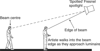
Figure 18.1 Subject movement – use of a spotted luminaire
- use a luminaire with a very long throw, so that the effects of inverse square law are minimised, i.e. follow spot
- avoid the artiste walking directly towards the keylight
- use half-scrims or veils to even out the illuminance when walking towards a keylight (Figure 18.2)
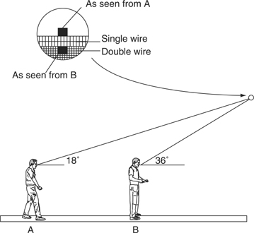
Figure 18.2 Subject movement – use of half-wires/scrims/yashmaks
- use two identical luminaires to cover the artiste’s two acting areas and arrange a suitable ‘cross-over’ or ‘take-over’ between the two luminaires (see p. 223)
- use the bounce technique to produce a ‘graded’ walk (see p. 225).
Dimming the keylight is fine if the keylight can be localised to the artiste, i.e. not lighting backgrounds or other artistes seen in shot, provided it is not a noticeable change in colour temperature. It must not cause problems for the next shot, with the keylight dimmed.
Stopping down the iris is a better option (no change in colour temperature), but the same principles apply, the artiste must be seen in isolation.
A spotted luminaire can sometimes solve the problem, where the artiste starts in the beam centre and as he/she walks towards the luminaire they move progressively into the edge of the beam. An alternative to this, often used on location work, would be to start with a spotted lamp and progressively flood it as the artiste walked towards the luminaire. Again, the luminaire must be localised on the artiste.
The use of half-scrims, half-wires, veils or yashmaks is the common technique for helping to provide even coverage. These have been introduced during earlier discussion. The essential requirement for these to work is that there must be a significant change in the angle between the keylight and the artiste (Figure 18.2).
The half-scrim provides a very soft edge to the start of the reduction in illuminance because it is very close to the lens. Veils and yashmaks have to be positioned close to the lens if they also are to give a smooth reduction in illuminance. A small incident light meter, e.g. Sekonic, is ideal for checking illuminance at position A and position B before deciding which scrim/veil to use. An alternative to using scrims or yashmaks would be to use half white diffusion in a colour frame close to the fresnel lens.
18.2 Lighting for Subject Movement – Setting a Crossover
Where a large distance separates the two acting areas, and it is not practical to use one keylight, two keylights with a suitable changeover between them is the solution. Before discussing this technique it is worth examining some salient points about barndooring:
- Barndoors are most effective when the luminaire is fully flooded.
- The barndoor produces the ‘sharpest’ cut of light when its edge is farthest from the lens.
- The degree of barndooring ‘sharpness’ increases as you get nearer to the luminaire. This is a particularly important point when setting a crossover, and can be checked by putting a luminaire on a floor stand at head height. Set it to, say, 6 m and put the large barndoor vertical and at 90° to the lens. Observe how much you have to move your head from seeing all the hot spot to seeing none of the hot spot. At 3 m it will probably be about 0.5 m, and at 6 m it will be about 1 m. Incidentally, note how the hot spot follows you as you move within the beam.
- The barndooring sharpness depends on the sharpness of the hot spot image. This is controlled by the particular Fresnel lens and the amount of diffusion introduced on the rear of the lens. A well-defined hot spot will give sharper barndooring than one with a diffused image (Figure 18.3).
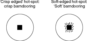
Figure 18.3 Hot spot ‘sharpness’ (Fresnel spotlight)
Incidentally, if you see two hot spots, it means that the mirror/lamp base assembly is loose or bent in some way. Normally, the reflected image of the filaments should ‘lie’ over the actual image of the filaments, to produce one hot spot. Sometimes, ‘saggy’ filaments can give rise to one image being slightly displaced from the other.
Beware of trying to achieve ‘sharp’ barndooring from a luminaire which has got two hot spots, it will not be (Figure 18.4)!

Figure 18.4 Double hot spot (Fresnel spotlight)
Figure 18.5 illustrates the problem of lighting the artiste for position A and position B, with a walk between A and B.

Figure 18.5 The setting of a crossover
To ensure a good crossover, the following points should be observed:
- The artiste should walk towards his keylight, i.e. not turn away from it.
- Both keylights should be identical luminaires and accurately set on position A and position B, respectively.
- The keylights need to be at similar heights, similar angle and similar distances to each area.
- The keylights should be fully flooded.
- The illuminance at area A and area B should be adjusted to be the same.
Ideally, the crossover should be disguised by the action so, in the above case, it is suggested to complete the crossover immediately the artiste starts walking at X. The sequence of operations for setting the crossover would be to adjust the barndoors as indicated in Figure 18.5. This is something of an ‘ideal’ case. In practice, the barndooring of Key A will be sharper than that of Key B, and Key A will be providing more illuminance than Key B (Key A is closer to the artiste).
Depending on circumstances, half-scrims or veils can be used to control the change in illuminance as Key A is approached. Some practitioners find it easier to simply use scrims/veils or even half white diffusion on Key A to produce a gradual reduction in illuminance, as Key B is moved into.
The above technique is worth practising on a quiet day to perfect your own technique. It is useful to have a small analogue incident light meter to check the evenness of the walk; aim initially at a spread of illuminance within half of one f-stop and see if you feel that this is satisfactory. Start with a 30° angle between keylight and camera, then progress to 0°! When confident with two luminaires, try setting the crossovers for three luminaires, i.e. two crossovers.
Obviously, the backlights can be treated in a similar way for barndooring, but not so critical as the keylights. Fill-lights are used to provide a base light of illuminance.
18.3 Lighting for Subject Movement – Alternatives
- On location there may be a need to cover a long walk without getting lighting stands in shot. The problem here is to maintain lighting level and vertical keying angle. One keylight could satisfy the needs for lighting the start of the walk, but at the end of the action the vertical keying angle would be too steep. This can be resolved, as shown in Figure 18.6, by using two luminaires with a vertical crossover between them.
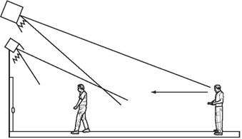
Figure 18.6 Artiste movement coverage in a long walk
- Use of bounce techniques to cover artistes’ movements provides a very quick and easy way to provide the necessary cover. The principle is illustrated in Figure 18.7 and use is made of the cosine law nature of the light reflected from a diffuse reflector. The centre of the reflected light is directed at the furthest area. For this to be effective, there must be a significant angle difference between the start position and the end position. This is to ensure that as the artiste walks from A to B the ‘angle change’ to the reflector ensures that, due to the cosine law, he receives less illuminance.
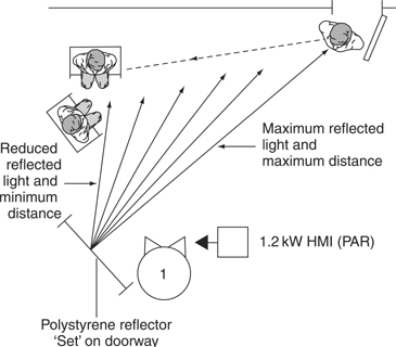
Figure 18.7 Use of ‘bounce’ to cover artiste movement
If there are any hot spots on the walk, these can be minimised by placing an appropriate size of veil between the reflector and the artiste. The above technique may also be used to light a stairway in a large foyer (Figure 18.8). At the top of the stairs it is a horizontal key, but the artiste looks down so this is acceptable.
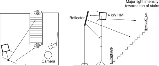
Figure 18.8 Use of ‘bounce’ to light subjects descending ‘open’ stairs
- Fluorescent lights fitted with 60° control screens can be extremely easy to adjust to provide a suitable crossover from one to the other. The soft edge to the light beam means that, with careful adjustment, one can get a smooth transition from one to the other.
A word of caution on the subject of crossovers/walks. Avoid the situation of a significant increase in lighting level during a walk – this will be most noticeable to the viewer. On the other hand, a slight reduction in illuminance will tend to appear to be more natural and will be accepted by the viewer.
As a rough guide, you should aim to get the coverage on a walk to be within ½ of one f-stop to ensure that any variations in exposure are minimal i.e. ± ¼ of one f-stop.
Fractional f-Stops – How Much is a Half-Stop Change in Illuminance?
Many lightmeters are calibrated in fractional f-stops. The f-number series is a logarithmic series with a ×2 increment in exposure between each f-stop. So a half-stop increment will result from two identical numbers which multiply to give 2, i.e. √2= ×1.4, or ×0.7 if reducing exposure. Similarly a one-third stop increment results from a change in exposure by × ![]() = ×1.25 and a quarter-stop increment requires a change in exposure of
= ×1.25 and a quarter-stop increment requires a change in exposure of ![]() = ×1.19. Summarising,
= ×1.19. Summarising,
| +½ f-stop = ×1.4; | –½ f-stop = ×0.7 |
| +1/3 f-stop = ×1.25; | – |
| +¼ f-stop = ×1.19; | –¼ f-stop = ×0.84 |
18.4 Creating Mood – the Implicit Requirements
Reading the script will reveal the explicit requirements such as day, night, dawn, sunset etc. as straightforward statements. The mood or atmosphere will be indicated as an implicit requirement, often being determined by the interpretation of the reader. It is essential that the lighting is completely in sympathy with this requirement, following effective planning with the director.
Lighting will have a major impact on the created mood or atmosphere in a scene. Costume, scenery and make-up all have a part to play in creating the right mood but they all require lighting to be correct for the scene to work effectively.
Mood can be described as any departure from ‘normal’, although of course ‘normal’ itself represents a particular mood. The lighting factors affecting mood are:
Texture
Modelling/contrast
Ambiguity
Clarity
Colour
Exposure
Texture – subjects look more interesting and appear more realistic when texture is revealed to a maximum, i.e. the nature of the surface is revealed by using a large angle between the keylight and the camera. This applies equally to buildings and to people. Dark clothing, for example, is best revealed when lit for texture. Maximum texture will help in the creation of dramatic-looking pictures.
Modelling and contrast – these two factors have a major impact on mood, with more dramatic pictures resulting from lighting which creates maximum modelling (increased shadow areas) and high contrast. Remember to shoot the shadow side of the face, not the lit side, otherwise the modelling will not be revealed to maximum effect.
The term ‘key’ is often used to describe mood, namely:
The distribution of tones and tonal contrast
High key – predominance of light tones within the picture, little shadow (modelling) with low contrast. The pictures have a light cheerful look, almost two-dimensional in appearance. Lighting ratio approx. 1:1 for keylight and fill-lights.
Medium key – ‘normal’ distribution of tones within the picture. Typical lighting ratio approx. 1:2.
Low key – predominance of dark tones and ‘heavy’ shadows. Typical lighting ratio approx. 1:4 or greater.
Ambiguity relates to the degree of uncertainty created by lighting. The more ambiguity created, the more mystery created. The lighting of an actor may require just the eyes to be lit or conversely only lighting the lower part of the face, thereby inducing mystery, i.e. who is this person – what is he thinking? Another example would be an exterior moonlit scene. A building lit with a large HMI could be transformed from a ‘clear moonlight night’ to one which introduced mystery and uncertainty by using a suitable ‘cookie’ (dapple-plate) or tree-branch gobo in front of the light source.
Clarity in terms of image sharpness and contrast is another factor affecting mood. Camera filters can be used to modify these parameters. The filters are graded in sets of 5, where Filter 1 provides the most subtle effect and Filter 5 results in the most severe effect. This enables the choice of filter to suit each situation, i.e. zoom angle and severity of effect required. On-camera filters are most effective at wide apertures, i.e. f2.0–f2.8. Some of the filters, e.g. Promist, have more subtle grades, i.e. ¼ and ½. See p. 228.
Before using filters for a particular requirement, it is recommended to experiment with them to determine the most appropriate filters – thus saving time on the shoot day. Use a large, good-quality monitor to assess the filter effects. Camera detail, electronic sharpening of the picture, will also have an effect on the overall picture sharpness.
Colour – the psychological effects of colour has been mentioned elsewhere in this text, namely:
- Red/orange colours are associated with warmth, friendliness.
- Blue colours are associated with cold, night-time, unwelcome feelings.
- Green, as pastel shades can be used to create a cool environment, with deep greens suggesting evil.
Lighting balance – the relative brightness of each part of the picture contribute to the overall effect. A correctly aligned picture monitor or viewfinder can be used for this or a simple ‘pan glass’. The latter is a great asset in judging relative brightness – although, of course, the monochrome viewfinder picture also does this!
Exposure – it is so important to get exposure right! Having lit the scene to get the right mood, exposure is the final judgement that ensures that it looks right. Provided the viewfinder is correctly set up consistently, a cameraman will make good exposure judgements – based on experience. The Zebra pattern can be used to ensure no overexposure occurs or to make judgements in exposure, i.e. one step down on ‘normal’ exposure. A waveform monitor is another useful aid.
18.5 On-Camera Filters
Television camera manufacturers strive to produce cameras which have the highest possible specification in terms of picture sharpness and tonal gradation of the picture. Often, however, there is often a need to move away from the ‘technically perfect’ picture to create a particular mood or simply for cosmetic reasons, e.g. the ‘sharp’ camera and hard lighting revealing too much texture on facetones! Camera filters may be used behind the lens (filter wheel) or in front of the lens on a matte box.
The matte box provides the facility for easy rotation of the filter as required and easy change of filters. It is also useful as a lens hood to reduce stray light entering the lens, which helps to maintain contrast and definition of the optical image.
Most filters are available in sets of five, where filter 1 has the most subtle effect and 5 has the greatest effect. Some filters also include ½,¼ and 1/8 within their range to provide very subtle effects. Usually the filters work best at wide-open apertures. However, the effect will also be affected by lens angle of view.
It is always a good policy to experiment with filters before you use them on a shoot. Observe the effect on:
Facetones
Picture sharpness
Changes to highlights, possible ‘halo’ around highlights
Changes to black level, reduction in picture contrast
Always use a large good-quality monitor (ideally Grade I or II) to assess the effects of the filter. Some of the more commonly used filters are described below.
Nets – available as black, white or skintone. Black nets soften the ‘electronically’ sharp television image, reducing the visibility of facial blemishes. White nets perform similarly, but if the filters are backlit the image will be ‘sat-up’ by the ‘flare’ introduced by the net. The skintone filter introduces soft diffusion and enhances skintones.
Fog filters – operate by scattering the light, having the greatest effect on highlights, with scattering the highlights into the shadow areas. Resolution is reduced.
Double fog filter – produces a more neutral-looking fog while allowing clearer detail than a standard fog.
Graduated fog filter – used to produce fog at the top of the picture and clear at the bottom. This results in progressively more fog from foreground to background.
Promist – results in removing harsh edges on electronically sharpened pictures, introduces a small amount of flare, which reduces picture contrast slightly.
Black Promist – a very popular filter, similar to the Promist but with a more subtle reduction in contrast (less flare into the shadow areas).
Soft/FX – useful for portraiture, it will reduce wrinkles and skin blemishes while retaining overall clarity. Eyes appear sharp.
Warm Promist and Warm Soft/FX – combines a warm filter with the effects filter.
Colour Grad filters – these are coloured filters, which are half clear and half coloured with a smooth transition from full colour to clear. Usually used to create coloured skies, taking care to keep the artistes, faces in the ‘clear’ zone.
ND Grad filter – similar to Colour Grad but in neutral density, useful to help cope with excessively bright skies.
Neutral blended ratio attenuators (NBRA) – similar to an ND Graduated filter except that the graduation is over the whole filter. A one-stop NBRA has a one-stop loss in the centre, two stops at the dark edge and zero loss at the light edge. These filters can be useful to reduce the contrast in a scene, which is part in shadow and part in sunshine. The filter is rotated in the matte box so that the denser part is coincident with the brightly lit area. Opening up one stop to compensate for the filter results in the exposure on the foreground (shadow) being increased by one f-stop and the background (sunlit area) being reduced by one f-stop. A two-stop NBRA would graduate from four stops ND to zero.
Polarisers – reduce ‘glare’ reflections, resulting in improved colour saturation. They can also be used to darken blue skies to improve contrast with clouds. Remember they have approximately a two-stop loss.
Contrast handling filters – can be used to reduce the contrast ratio between highlights and shadow areas, without loss of sharpness. These are three basic types:
- Ultra contrast filters – which introduce ambient light and light from the image area into the shadow areas, but do not result in flare or halation on light sources or hot spots.
- Low contrast filters – spread light from the highlights into the shadow areas, they produce a slight halation around the light sources or hot spots.
- Soft contrast filters – absorb light, diminishing the highlights while retaining the shadow detail, again giving a slight amount of halation.
18.6 Lighting Effects
Often there is a need to create special lighting effects. To ensure that an effect is going to work for a particular venue/requirement it is recommended that a ‘test’ of the effect be made beforehand. The following are typical effects:
Sunrise/sunset – This obviously requires a warm feeling to the lighting. The light source used needs to be at least ½CTO warmer than the ambient lighting, i.e. a MIRED shift of+109 MIREDs. If the camera white point is at 3200K (a tungsten-lit scene) the ‘sunset’ effect can be created with a low elevation tungsten source +½CTO filter. If the white point is at 5500 K (daylight-lit scene), then use either an HMI/MSR+ ½CTO filter or tungsten source with a ½CTB. Depending on the degree of warmth required the filtering could be increased to ¾CTO and ¼CTB respectively. Hence the value of the test. To ensure that the sunlight effect works, it is important that it is not contaminated with any other source, i.e. seen clearly without any mixing with other sources.
Night-time – this has been covered in detail elsewhere (p. 252).
Fire-flicker effect – There are several electronic fire-flicker effects available to help in the creation of this effect. Despite these, one of the simplest and most effective ways of achieving this effect is to use strips of rag on a broom handle (Figure 18.9). These are shaken in front of a floor-mounted spotlight. Use full CTO or ¾CTO filters on the light source to give the appropriate colour (camera white balanced to tungsten). Very dramatic effects can be achieved by using the light source relatively close to the action, which results in large shadows of the artiste on any adjacent walls.
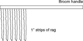
Figure 18.9 Fire-flicker device
Water-ripple effect – To suggest action near water, use a black water tray 0.6 m x 0.6 m x 0.1 m with broken mirror in the bottom, and half-fill with water. Use a hard light source (Fresnel spotlight) to bounce light off the water and the mirror. The light source should be used close to the tray to collect all of the light beam and the water should be disturbed slightly to obtain the water ripple effect on the set or the artistes (Figure 18.10). An alternative to this would be to use a profile projection with a moving water ripple effect. This would tend to give a more ‘regular’ effect and not as random as the water tray.
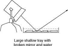
Figure 18.10 Water-ripple effect
Candlelight – It is always useful, when working with coloured light on faces, to have the motivation for colour in shot, in this case the candle flame, and the candle. Figure 18.11 illustrates a possible set-up. The important points here are:
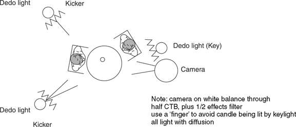
Figure 18.11 Candle-lit scene
- The candle must not be illuminated – use a ‘finger’ to block any light from the keylight.
- The candlestick must be ‘warm’. It is therefore more realistic to ‘warm-up’ the camera by white balancing through a ½CTB or ¾CTB to ensure that the complete scene is warmed up. This saves time on filtering the light sources. Other variations on this would be to white balance through ½CTB and use a ½Black Promist, ½Warm Promist or ½Warm Soft Effect filter on the camera. These will soften the image, and add a glow to highlights, i.e. the candle. One drawback in this scenario is that the true colour of the candle flame is only seen at about f16. This reinforces the argument for moving the white point. Not only does the candle become warmer but also the flame.
Lightning – Best achieved with special ‘lightning’ units (see p. 134), ora large HMI/MSR fitted with a manual semaphore shutter to enable rapid ‘flashing’ of the light. Lightning effects should be very intense, best used as side-lights or back-lights. Frontal use of these lights will ‘wash-out’ the scene.
Light beams – For light to be made visible in the atmosphere it must hit something, e.g. mist, fog, smoke and dust particles. The two essential items for revealing light beams are:
- Strong light sources – sun, HMI PARs, Xenon, large Fresnel spotlight, narrow-angle PAR cans.
- Haze machines/fog machines.
Haze machines are ideal for use in enclosed areas where a general haze can be built up over a period of time and easily maintained. They provide a very even haze. Fog machines are more useful for exterior work, capable of providing large quantities of fog. Some machines have coolers, which cool the fog which then dispenses more slowly. Obviously on a windy day use of an exterior fog machine is going to present problems!
For best results, haze and fog should be backlit, or sidelit to reveal the light beams. Incidentally, water droplets as in fountains should be lit in a similar way for best effect.
18.7 Lighting Demonstrations
Examples of demonstration shoots include cooking items, gardening and do-it-yourself repairs and renovations. The simplest demonstration set-up is that of a single artiste to camera, shooting mid-shots and medium close-ups of the artiste supplemented with close- ups of the item being demonstrated. If shooting with two cameras it can be shot very quickly, keeping one camera on the presenter, the second on the close-ups of food etc. Shooting single camera requires the presenter to be shot and then the close-ups shot as cut-aways. Unless the presenter technique requires everything to be shot on an obvious single-camera, i.e. panning and zooming to follow the action, not a technique which endears itself to viewers! Figure 18.12 illustrates a typical lighting set-up based on the need:
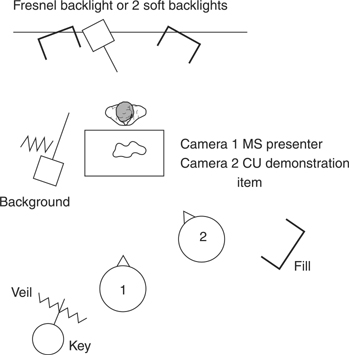
Figure 18.12 Basic demonstration, lighting for a single presenter
- To provide modelling (form) for the presenter and the item being demonstrated.
- To avoid camera shadows on the demonstration item. Remember, the close-up camera will probably need to crane-up and tilt down to look at the items being demonstrated. Similarly the presenter’s camera will need to be on the eyeline, i.e. elevated. Hence the need for an offset keylight as shown.
- To avoid overlighting the front of the table, use of a veil on the keylight is a more precise way of controlling the lighting on the front of the desk than a barndoor.
- To avoid hard shadows of the presenter over the items being demonstrated. Use:
- an offset backlight
- a kicker – this can be barndoored off the table
- two ‘soft’ backlights
Note: when using soft backlights there is a need for these luminaires to be fitted with egg-crates and tipped down to avoid camera flare. Also be aware of light spill from these lights lighting the background.
The above lighting plot is a basic solution to the problem. Note, however, that there may be a need to reverse the keylight/fill-light position if the item being demonstrated is not clearly defined. Remember, clarity of the demonstrated item is paramount!
This basic set-up may be extended to cater for a two-person presentation, i.e. host plus guest, as shown in Figure 18.13. In this, the guest is placed camera right so that the keylight favours him/her, i.e. the guest turns towards the keylight when talking to the host.
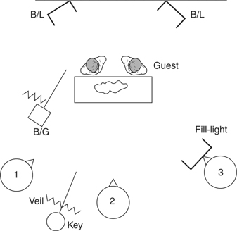
Figure 18.13 Two-handed demonstration, basic plot
An alternative solution is shown in Figure 18.14 using ‘cross-keys’. This set-up is useful when the presenters favour more of an interview discussion rather than working downstage as previous example. Note the use of side half-scrims on the keylights to reduce illuminance on the nearer of the two presenters. One of the keylights needs to be barndoored off the table top to avoid it being overlit.

Figure 18.14 Cross-lit demonstration
A by-product of this technique of cross-keying is that the presenter’s shadows are less likely to appear in shot than with the more frontal keylight. Where possible avoid in-shot presenter’s shadows, i.e. on backgrounds, unless using large softlights as keys – the soft shadows are less distracting.
To avoid the artistes’ shadows on the background, try to gain a good physical separation between the background and the presenter – at least 2 m. If shadows of the presenters on the background are a distraction consider:
- using a frontal keylight – shadows will be behind presenter
- using a side-key plus frontal fill-light.
18.8 Pack Shots
Pack shots are shots of ‘packages’ which exclude a presenter, e.g. a product or a prize, seen in isolation. Many items are straightforward to light, and the general principle is to keep it simple and try to avoid conflicting shadows. Often, effective lighting can be achieved by using a soft keylight from upstage, offset to one side. The keylight also acts as a backlight giving good separation on the items being featured, e.g. a plate of food. A complementary soft fill-light from downstage completes the set-up (Figure 18.15).
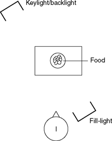
Figure 18.15 Basic lighting of food
Pack shots may give rise to glare reflections of the light source. These can be controlled by using a polarising filter on the camera. If direct reflections of the source cause problems, these can be controlled by polarising the light source as well as using a polariser on the camera. Glass and metal objects present particular lighting problems and are worth special treatment.
Lighting Glass
Glass being transparent is difficult to light. Most of the light is transmitted by the glass, and a small amount is absorbed and a small amount is reflected. The light reflected will give rise to a specular reflection that may be a distraction. Two techniques have evolved for lighting glass:
- Bright-field method
- Dark-field method.
The Bright-field method relies on placing the glassware in front of an illuminated background with black drapes either side of it. The glass is unlit! The luminaire lighting the white background must be ‘flagged’ to ensure that no specular reflections are seen in the glass (Figure 18.16).
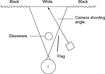
Figure 18.16 Bright-field method
This reveals the glass as slightly ‘smokey’, due to less than 100% transmission of the glass with dark edges to the glassware. The dark edges are the black drapes, refracted by the glass. Coloured filters over the background light can be used to great effect. Note, however, that if translucent liquid is introduced into the glass it will turn the glass/liquid into a lens with a consequent reversal of background colour position. If extra shape is required, a reflection of a ‘window’ can be introduced on the glass by using a white reflector downstage with black tape ‘glazing bars’ and bouncing a suitable Fresnel spotlight. A similar technique of revealing the shape of, say, a wine bottle can be used, and it also provides illuminance for the label.
The Dark-field method, as its name suggests, is the reverse of the Bright-field technique, i.e. the glass object is seen against a black background with out-of-shot white cyclorama either side of it. Figure 18.17 illustrates this technique.
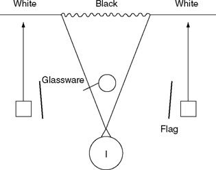
Figure 18.17 Dark-field method
Again, care should be taken to ensure that no specular reflections of the light source are visible on-camera, unless specifically requested. This technique is especially useful for cut- glassware. The image seen on-camera will be that of the glassware against black with the edges showing as highlights – the refracted images of the white drapes. Again, colour can be used to good effect, and downstage soft sources can be used to reveal engravings in the glassware.
Lighting metal, particularly polished metal, usually requires the light source to be revealed (Figure 18.18).
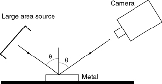
Figure 18.18 Basic technique for lighting metal
Often it is useful to add some ‘texture’ to the reflection by putting small flags or ‘Charlie bars’ over the light source. Silver trophies are usually put in a ‘tent’ of diffusion which is lit from outside. The camera shoots through a small hole in the ‘tent’.
This technique is extended for lighting a car. The usual brief is no ‘speculars’, the car must look sleek and elegant! Observe a car, outdoors, on an overcast day, and the technique for lighting a car will be revealed! The convex curves of the car reflect the sky and at the same time produce a minified image. This results in a car with highlights (the reflected sky) on all the curves, which help to accentuate the ‘lines’ of the car. At the same time, of course, the car is lit with the skylight. In a studio, this can be realised with the car, against a cyclorama, with a large butterfly above. The butterfly fitted with silk or diffusion is lit from above, usually hard sources, but if a perfectly diffused light source (from the butterfly) is required, one could use softlights (Figure 18.19).

Figure 18.19 Lighting a car - basic technique
The cyclorama can be lit to provide appropriate illuminance of the car sides. If artistes are required to be lit, standing alongside the car, use a Fresnel spotlight, which has been well flagged off the car (to avoid specular reflections).
18.9 Conference Lighting
Conferences may take many forms, from a simple single subject to a panel of politicians at a party conference. Points to remember include:
- The subject should be able to see the audience and it is essential that the questioner grilling the speaker should be seen by the speaker. Remember, a vertical keying angle of less than 30° will result in glare for the subject, i.e. well aware of the light source in his eyeline.
- Try to avoid distracting shadows of the speakers on the background. Remember the need to keep the subjects well away from the background – ideally about 2.5 m, or 1.5 m as the absolute minimum.
- If an in-shot shadow on the background cannot be avoided, say, for an end-of-match interview against a background of programme/sports logos, make sure that the subject is lit from within the picture so that the shadow falls behind the subject, not in front of them. Using diffusion on the light source will reduce the amount of distraction of an in-shot shadow.
- When multiple subjects are involved avoid mutual shadowing.
- When large halls are involved, try if possible, to gain a camera position at the front of the hall. This will avoid the need for any range extenders and the higher lighting levels subsequently needed.
- Usually large conferences have a lighting truss rigged in front of the conference speaker’s table. This gives a good facility to divide the ‘table’ into sections, lighting each section separately. Always use Fresnel spotlights to have the good control of the beam shape, i.e. provide localised lighting.
- The various options are illustrated in Figure 18.20.
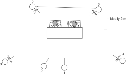
Figure 18.20 Basic alternatives. Lamp 1 used as a frontal keylight if shadow on background is a problem; Lamp 2, better position for keylight if no shadow problem; Lamps 3 and 4 may be used as fill-lights (multi-camera shooting) or as cross-keylights if audience prevents positioning of 1 or 2; Lamps 5 and 6 backlights: 3, 4, 5, 6 with diffusion
- Presentations against projection screens require good control of light beams to ensure that the projected image is not washed-out with stray light (Figure 18.21).
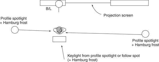
Figure 18.21 Presentation against a projection screen
18.10 Silhouette Lighting
Often when subjects do not want to be recognised they need to be seen in silhouette. Basically, this means shooting the unlit subject against a brightly lit background. It is obviously essential that the facetone is at black level. How can the cameraman ensure this?
With all vision control work, the most important aspect is invariably the face. Generally, for normal operations, the face is exposed to be about one stop down on peak white.
Typically, the dynamic range of a colour camera is in excess of 32:1, i.e. equivalent to our five stops. From the discussion on dynamic range, recall that the nine-step grey scale has a contrast ratio of 32:1 between the peak white step and the black step (Figure 18.22). But the black step results in a signal above absolute black level. So if you want the subject to be totally in silhouette, it must be well over five stops down on the lighting level used for the background. The easiest way to achieve this is to shoot the subject against a window. With no light on the subject, expose the sky – the subject will be in total silhouette.
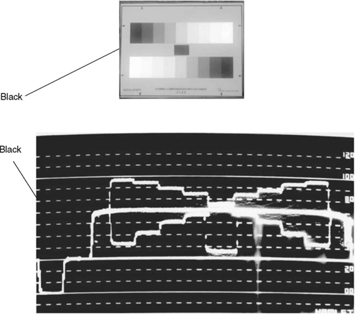
Figure 18.22 The visibility of a ‘black’ step
For interiors at night, light only the background to a high lighting level, again removing all light from the subject. Remember, you need at least five stops’ difference – a lighting ratio in excess of 32:1, preferably six stops.
For exteriors, use some form of flag to keep the light off the subject and shoot against the sky or a plain light wall. But again, remember the need for at least a five stop difference in luminance of background and subject.
As a check, open up your camera to exposure the face and note the f-number. Now stop down to correctly expose the background and note the f-number. The difference in f-number should be over five stops and your silhouette will work!
If your camera has DCC or some form of knee, switch it off for the silhouette shot. But do remember that you are not trying to ‘burn-out’ the background. Opening-up to achieve this will raise the exposure on the subject and may make him visible.
Always frame the subject so that the silhouette has some degree of ambiguity, i.e. not square-on or full profile. If in any doubt about the visibility of the face then shoot the shadow. This will have some degree of distortion. As a further measure, the shadow could be arranged across a radiator or drapes, again giving extra ambiguity to the shape of the silhouette (see Figures 18.23 and 18.24).
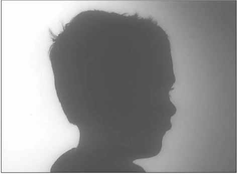
Figure 18.23 Basic silhouette, offset to disguise shape
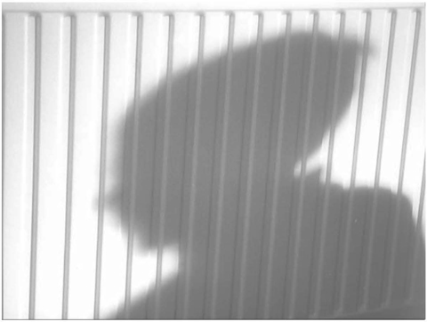
Figure 18.24 Use of shadow on a textured surface to disguise the shape
18.11 Chroma Key on Location
Often it is required to complete a chroma key foreground shot on location for insertion into an appropriate background in post-production.
Chroma key Principle
Chroma key is an electronic process whereby part of one picture (foreground) is inserted into another (background) (Figure 18.25). The area to be inserted is determined by placing the foreground subject in front of a suitably coloured backing, e.g. blue or green. The RGB signals from the foreground camera are used to devise a suitable keying or switching signal which is used to operate a fast-acting switch between foreground and background cameras. Whenever the keying signal is of a high amplitude (when scanning the keying colour) the background picture source is selected.

Figure 18.25 Chroma key principle
The Keying Signal
The keying signal is derived from the RGB signals such that it is a maximum for the keying colour. Unfortunately, colours in the foreground subject which have the keying colour in their make-up may give rise to a keying signal, producing erroneous switching. To provide discrimination against unwanted colours operating the switch, the keying signal has to rise above an operational clipping level.
Chroma key systems, therefore, use two steps to derive a suitable keying (switching signal):
- a saturated colour backing – hence chroma key
- an operation threshold or clipping level.
Lighting for Chroma Key
The lighting of a foreground chroma key set-up requires a few basic principles to be
observed to ensure successful chroma key operation in post-production.
- The backing colour should be lit uniformly and to a minimum level, consistent with correct switching. Typically, the backing should be lit to a similar level as the foreground subject. Collapsible backgrounds in green/blue are available.
- A good depth-of-field is required which ‘embraces’ all the foreground planes. Any lack of sharp focus on foreground planes will result in a ‘mix’ between subject edges and the keying colour, i.e. providing uncertainty in setting the clipping level.
- Avoid subject shadows on the keying background, unless ‘shadow’ chroma key systems are being used. The clipping level would have to be reduced to operate on the darker backing, perhaps allowing unwanted colours to key.
- Use two backlights to provide a good rimlight to the foreground subject. This will washout any colour fringing on the foreground subject. A single backlight will not give complete wash-out of the fringe.
To minimise colour fringing of the foreground subject:
- Keep the foreground subject well clear of the background.
- Keep the luminance of the background as low as possible.
- Use two backlights.
- Use minimum area of keying background.
If the background subject is known in advance, the lighting of the foreground subject should relate to it, e.g.
- Keylight from an appropriate angle
- Use hard/soft keylight as appropriate
- Use coloured light as appropriate, i.e. warm/cool
- Shadow density to match background.
For matching purposes record:
- Camera height
- Camera lens angle
- Subject distance
- Camera tilt angle
- Lens aperture.
If the inserted background is to be a simple graphic then matching of foreground and background becomes less important.
18.12 Lighting Musicians
Musicians and their instruments can provide some of the most interesting subjects to light:
- Remember if the musician is reading music to keep the keylights well away from his eyeline. Bright point sources can give rise to dark ‘after-images’ and the musicians will complain about too many notes on the music!
- With orchestras it is most important to avoid keylights on the musician’s eyeline to the conductor for the same reasons.
- Each musician, if lit individually, needs to be lit to avoid the shadow of the instrument falling on the musicians face, e.g.
Trombone
Trumpet
Harp
Flute
Tuba
French horn
Violinist’s bow.
- Usually stringed instruments require the musician to be lit from the stringed side of the instrument, i.e. from the direction which the musician will tend to look to check fingering etc., e.g.
Double bass
Cello
Guitar.
- Close-ups of the musician’s fingers will always be required. Ensure that you have an effective backlight to bring out the shape of the fingers and to separate them from the background.
- Avoid overlighting – a short depth of field is an advantage when shooting musicians and detail shots.
- If using coloured light it is useful to keep a colour theme – appropriate to the music, e.g.
Black/white plus one colour
Black/white plus two colours.
- Keep coloured light pure – avoid contamination of colour caused by two colours ‘mixing’ on stage, i.e. keep coloured light, on one subject, more than 180° apart.
- Choice of colour usually includes the palette of blues, reds, oranges and lavender. Lavender seems to be a colour which will go with any colour. (Colours used should suite the mood of the music and complement or contrast with the musician’s costume. Figure 18.26 illustrates the basic colour wheel.)
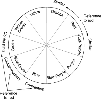
Figure 18.26 Basic colour ‘wheel’
- Green tends to work well when used in conjunction with instruments featuring woodwork – but use it in moderation!
- When lighting pop groups, using individual keys, light away from the centre of the stage, i.e. towards the edge of the stage. This is to avoid the centre-stage being overlit – the meeting point of all the light!
- When lighting a choir, keep lighting simple and try to use one keylight. Remember that if your light source is of sufficient beam angle but lacking in intensity, simply doubling the number of lights will obviously double the illuminance – and if using the combination at a long throw it will be most unlikely to see two distinct shadows.
- Conductors of choirs – try to avoid their shadow on the choir. The ‘lively’ shadow from an arm-waving conductor can be very distracting!
- Finally, lighting a piano Is generally regarded as a problem with a unique solution – there really Is only one way to light a piano keyboard properly! Figure 18.27 (page 245) illustrates the basic plot where the steep keylight is also the backlight for the piano and the pianist when shot on camera one.
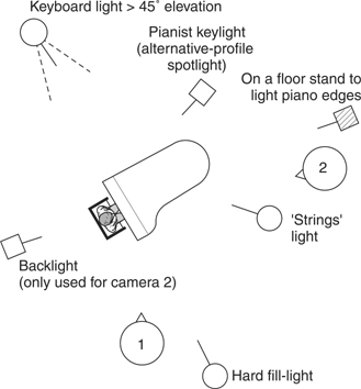
Figure 18.27 Lighting a piano
Note: Keyboard light must be steep to avoid long shadows of black notes. Avoid shadow of pianist on keyboard by placing keylight to aim straight along the keyboard. Avoid double keying of keyboard – make sure that the pianist’s keylight does not reach any part of the keyboard. Hence use of profile spotlight.
18.13 Lighting in Public Places (Supermarkets/Offices/Hospitals)
Supermarkets
The majority of lighting in supermarkets and departmental stores Is fluorescent, supplemented with tungsten/CDM lighting to give accents/highlights (Table 18.1). Most modern stores use high-frequency fittings to overcome the annoying flicker problem, which often occurs with mains frequency ballasts. The lighting will of course be ‘toppy’, although generally of sufficient illuminance for modern cameras. Depending on the nature of the shoot there may be a need to remove (flag) lighting to make pictures less ‘flat’. The problem with adding light is that of mixed lighting. Only when all sources are colour matched will the camera white balance result in a good colour fidelity picture, i.e. the camera will remove any excessive green hues during the white balance. Care should be taken in adding light to ensure that it is coloured matched to fluorescent lighting. Although matched in colour temperature, tungsten and fluorescent sources may have colour errors in the green/ magenta axis. Mixed lighting problems need to be solved at the time of the shoot. Only complete colour casts can be corrected in post-production.
Table 18.1 Supermarkets, department stores, offices and hospital lighting
| Area | Light source | Illuminance (lux) |
| Supermarkets | Colour 827 | 600–700 |
| Department stores | Colour 830 | 600 |
| Offices | Colour 840 | 300 |
| Offices (VDU) | Colour 840 | 500 |
| Drawing offices | Colour 840 | 500–750 |
| Hospital wards | Colour 840 | 600–800 |
| Operating theatres | Tungsten halogen | 60000–100000 |
Unless shooting under ‘controlled’ conditions, supermarkets will usually be full of shoppers making it difficult to use lamps on stands. Consequently any lighting will need to be with hand-held, battery-operated sources.
Offices
Offices are usually lit with fluorescent light sources at 4000 K. Offices with VDUs will be lit to about 300 lux and drawing offices will be lit to about 500 lux. Often to avoid problems of mixed lighting it is best to switch off the fluorescent lights and add corrected tungsten lighting to any existing natural lighting.
Hospitals
Generally hospital wards will be lit with fluorescent lighting, usually with localised tungsten angle-poise lamps near the bed-heads. Lighting equipment must never be plugged into hospital mains supplies without prior arrangements with the hospital authorities. This is another area where hand-held, battery-operated lighting equipment can be a useful supplement.
Operating theatres have special tungsten lighting over the operating table, supplemented with fluorescent lighting for the remainder of the room. Special arrangements have to be made for shooting in these areas to ensure that no contamination of the area or causing any obstruction to the procedures.
18.14 Stadia Lighting – Night
Sports stadia, football grounds etc. are generally lit with high intensity discharge sources, which have a correlated colour temperature of 5600 K. This colour temperature was arrived as a ‘preferred’ colour temperature for these events. Generally, when shooting interviews at these events, there is a need to supplement the stadia lighting; if possible use the stadia lighting as a backlight and add your own keylight. When adding extra light, make sure:
- It is colour matched to the stadia lighting
- It is at the right illuminance to give a similar exposure on the subject as the ‘background’ of the stadia
- It is diffused to avoid the subject being blinded by the light source
The last point is very important when lighting players against a stadium or cricket pitch in daylight. Often staging of the subject results in the subject having very little natural light on their face, e.g. under stadia roofs or cricket pavilions. You may find subjects objecting to very bright point sources in their eyes just before they go out to bat! Obviously, with sports such as cricket avoid any lights which may accidentally be on the batsman’s eyeline!
Lighting levels at stadia depend on the particular role of the stadium, often with three levels of floodlighting to cater for practice, club level and TV coverage. Many early installations were equipped with CSI sources (4000 K), but these are now being replaced with high intensity discharge sources at 5600 K. These match daylight more readily and enable film cameras to be used without any need for on-camera correction filters (Table 18.2).
Table 18.2 High intensity discharge sources (non-TV use)
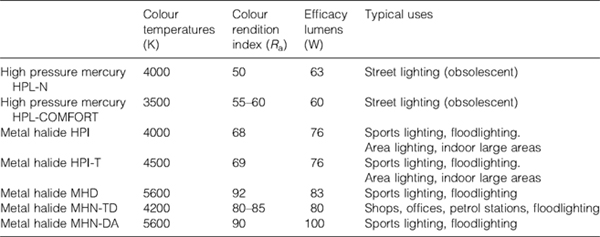
Note: With a wide range ot possibilities available tor tloodlighting, stadia lighting and public area lighting, it is recommended to check the light sources in use so that any possible mixed lighting problems can be evaluated.
The increase in camera sensitivity may be thought a reason to reduce the illuminance. However, the basic needs still need to be satisfied, namely visibility and clarity of players action for:
The players
The referee
The spectators
In many instances, the presence of television coverage has led to lighting levels which have benefited everyone! The increased use of slow-motion cameras has meant that the need for high lighting levels is maintained, and a minimum of 1400 lux is required with typical levels of 1800 lux being the design figure. Some sports require enhanced lighting levels in critical areas, e.g. goalmouth, dartboard, basket ball ‘basket’ area etc. to ensure a good exposure and adequate depth of field when using high-ratio zoom lenses (zoom ramping).
18.15 Stadia Lighting – Special Events
Often stadia are used to mount special events, concerts etc. where there is a need for long throw follow spotlights and/or xenon beamlights. The xenon light source is excellent for follow-spotlight applications:
- it is a very compact source, easy to collect and project the light.
- better efficacy than tungsten.
- excellent colour rendition (Ra 98).
- very stable colour with temperature and with life.
- very easy to match xenon sources.
The follow-spotlights have an optical system which incorporates a zoom lens. Consequently the beam angle and intensity can be varied, hence the follow spot data is quoted for both extreme conditions of beam angle. A variable iris is also included which can be used to adjust the size of the projected ‘disc’ of light (but with no change in illuminance).
Hamburg Frost and Light Hamburg Frost can be used in one of the follow-spot colour frames when requiring a soft-edged beam of light. This is better than defocusing the lens which results in a change in projected image size. Table 18.3 illustrates the performance typical of Xenon follow spotlights.
Table 18.3 Xenon follow spotlights

Xenon beam lights are extremely powerful luminaires, based on using a parabolic mirror system to produce a very narrow, intense beam of light. The optical system has a motorised focus mechanism allowing the beam to be altered from the lamp head, ballast or from a remote location.
One word of caution: the optical system does produce a ‘hole’ in the centre of the beam. This can be minimised, but avoid using beam lights as a form of follow-spot.
Table 18.4 illustrates the powerful nature of xenon beam lights. The remotely operated pan/tilt, beam focus, colour changer versions of these lights are known as Space Canons, Sky-tracker, Britelights etc.
Table 18.4 Xenon beam lights
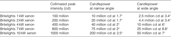
These luminaires are very powerful, and with the larger units in spot mode, the concentration of heat can crack windows! Nevertheless they can produce spectacular effects, the 16-frame scroller adding an extra dimension to an already impressive light source.
(Reminder: Xenon lamps may explode at room temperature, as the envelope gas pressure is above atmospheric pressure even when cold. Refer to safety handling instructions. All these units require forced air cooling, resulting in noise!)
18.16 Street Lighting
Sodium sources predominate in the world of street lighting, mainly for their very high efficacy. There are two basic types:
Low-pressure sodium sources – golden yellow in appearance
High-pressure sodium sources – orange/yellow in appearance
Low-pressure sodium produces light, which is basically monochromatic. Figure 18.28 illustrates the basic problem of shooting with this light source namely that the ‘single’ yellow wavelength excites the camera green CCD and predominately red CCD, resulting in red/orange pictures! This cannot be improved by any filtering on the camera or light source!
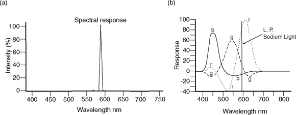
Figure 18.28 (a) Low-pressure sodium (SOX) spectrum; (b) Camera analysis plus SOX source
High-pressure sodium sources have been progressively developed to improve the colour rendition, but at the expense of the efficacy (Table 18.5). Their spectral energy distribution is shown in Figure 18.29 and the development in chromaticity is shown in the section of the CIE diagram (Figure 18.30).
Table 18.5 Sodium light sources
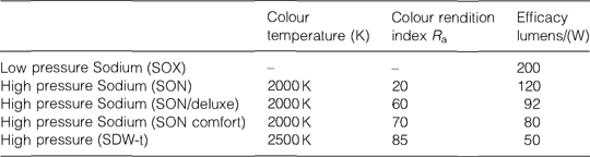
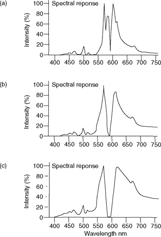
Figure 18.29 (a) High-pressure sodium (SON); (b) high-pressure sodium comfort (SON); (c) high-pressure sodium (SDW)
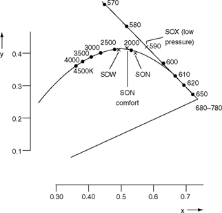
Figure 18.30 Chromaticity of sodium sources (figure shows part of CIE Chromaticity Diagram)
When using tungsten lighting and high pressure Sodium street lighting, the effects of the Sodium lighting may be reduced by suitable filtering. These are shown in Table 18.6. Clearly there is a need to test this to determine which street lights are in use. Alternatively, the local council highways department should be able to give the appropriate information on types of street lighting.
Table 18.6 Minimising the effect of sodium lights
| Street light source | Tungsten and filter | Appearance of street lighting |
| SON | No filter | Pink/orange |
| SON | –½green | Orange |
| SON COMFORT | No filter | Orange |
| SON COMFORT | Full CTO | White (match) |
| SON COMFORT | ¾CTO | Slightly orange |
| SON SDW | No filter | Yellow/green |
| SON SDW | – | White (match) |
For major shoots, the street lights could be fitted with the best appropriate light source or switched off and replaced with especially rigged ‘Blondes’.
Remember, when reading data sheets on street lighting, this will refer to horizontal illuminance values. Generally we are more interested in vertical illuminance values with vertical subjects!
Floodlighting of buildings is typically about 50–70 lux. Remember, again, that at night buildings need to be visible as lit backgrounds and not have ‘daylight’ values of luminance.
18.17 Lighting in Churches
Lighting churches for a service usually requires a full lighting rig and is normally shot as a live multi-camera outside broadcast. Single-camera operation in churches usually requires just part of a church to be lit at any one time. Several aspects should be borne in mind when lighting churches:
- Large old churches and cathedrals are usually quite dark when lit with natural daylight.
- Old churches usually have surfaces which are full of texture, and these should be lit to reveal the texture, i.e. large angle between the camera and the light source.
- Modern churches generally have flatter surfaces, which have a ‘lighter’ finish. There is a need for good control of light sources to ensure that these surfaces are not overlit, thereby causing a distraction.
- Often in lighting for texture on wood panelling, glare reflections may need to be controlled by using a polarising filter on the camera.
- Stained glass windows absorb a tremendous amount of light! During daylight they are backlit with a large area light source (skylight). Ideally, to reproduce this effect at night the windows needs to be lit with a large HMI (4 kW or larger) and the window lined with white diffusion or a silk. Simply lighting a stained glass window usually does not make it look very brightly lit. An image of the window will be on the ceiling – not in shot (Figure 18.31).
Figure 18.31 Lighting stained glass windows
- Where practical lights appear in shot, e.g. choir stalls, it can be extremely useful to insert a dimmer in their mains feed. This can give valuable control of their ‘in-shot’ brightness.
- Churches usually contain mixed lighting – candles plus daylight. It can be useful to white balance to ½CTB (4300 K) and use light sources corrected to ½CTB for the artistes. The candles retain a ‘warmth’ while the windows have a ‘cool’ look to them.
- For localised night shooting it is useful (and quick) to consider underlighting archways/ building features. This helps to create an atmosphere different from daylight and avoids the need of lighting equipment to be rigged at high level.
- Balloon lights have become popular for lighting large areas of churches/cathedrals (provided ceiling shots are not required).
- Church exteriors, at night, should again be lit for texture. Depending on the size of the building a 4kW HMI/MSR could be used for one side of a church, provided there is enough clear space for the use of the HMI far enough away to light the complete surface. If this is not possible, devise a lighting plan using several smaller wattage HMIs. Always use a flag to keep the light off the immediate foreground. Where two sides of a church are shot, it can be useful to ‘warm-up’ one side to give a slight colour difference to the second surface (Figure 18.32). Church windows should appear lit when shooting church exteriors, unless the church is supposed to be empty.
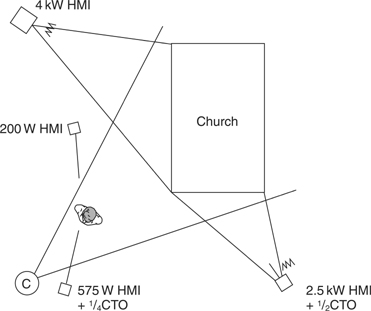
Figure 18.32 Church exterior
- If there is a need for ‘long throw’ lighting, the narrow angle PAR cans are particularly useful. They may be used corrected or not. In the latter case if the church/cathedral is very tall the daylight-lit upper parts of the building will be lit ‘cooler’ and have little effect on the congregation at floor level. Similarly, PAR cans can be useful for lighting church ceilings from the floor, again using narrow angle sources to contain the lighting to the ceilings.

18.18 Night-Lighting – Principles
The points to be considered for lighting at night on location are similar to those identified for creating mood, i.e. texture, ambiguity, colour, lighting, balance and exposure.
Texture is so important when lighting a shot at night. Typically, lighting a location so that it looks like night, i.e. dimly lit, but without texture being revealed results in pictures which will be uninteresting and flat. Clothing, especially dark clothing, is more readily revealed when lit for texture. The same is true for buildings.
Ambiguity, as discussed earlier, is a major parameter in creating an element of mystery. Night-lighting is very much an area for using dapple-plates (cookies) and simple ‘dingles’ (tree branches) in front of lights to create a shadowed and mysterious look to the location.
The colour of light used at night is an area for a major debate, and there are several opinions on what is best. Some Lighting Directors avoid coloured light completely, others use colour according to their own observation and what looks right for them. The correct placing of luminaires is important to create the right effect before considering the use of colour.
The potential light sources at night are:
- moonlight at 4100 K
- domestic tungsten at 2760 K
- street lamps (sodium) at 2000 K (low pressure) – 2400 K (high pressure)
- candles at approximately 1900 K.
So, what about the use of coloured light at night?
The stylised film treatment of using a fairly strong blue filter on lights or camera lens originates from the observation that at extremely low levels of illuminance, i.e. moonlight – 0.1 lux – human vision becomes monochromatic and we no longer see any colour, only a black/white landscape. One way to remove the colour from a scene, except of course blue, is to use a blue filter. This leaves the scene very blue.
Another argument for using blue is that when the eye/brain changes from photopic vision (full colour) to scotopic vision (night vision – monochromatic) there is a small shift in the peak response towards the blue end of the spectrum (Figure 18.33). This is sometimes used as an argument for using blue. However, the eye/brain sees this as a black/white image – not a very convincing argument to use blue!
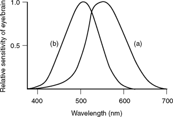
Figure 18.33 Relative spectral sensitivity of the eye/brain, (a) Photopic; (b) scotopic
Probably the best way to tackle the use of colour at night is to look at relative colour differences, say between moonlight and domestic tungsten. Moonlight is reflected sunlight, but without the presence of skylight, so it will be less than average summer sunlight, a colour temperature of 4100K is usually quoted.
A scene involving absolute reality is shown in Figure 18.34. This lighting plot could be realised with filtering of light sources, e.g.:
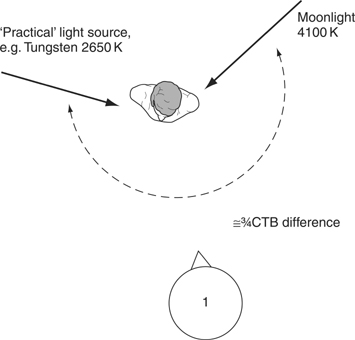
Figure 18.34 Night exterior scene – ‘reality’
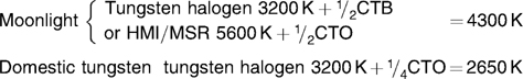
A simpler solution would be to minimise the amount of filtering by just ensuring a difference between the sources in the correct colour shift-that is the correct MIRED shift, in this case a ¾CTB difference.
18.19 Night-Lighting – Practice
A practical solution to the ‘reality’ situation discussed above is shown in Figure 18.35. Another filtering alternative is to use (Full CTB + White Flame Green) in combination to give a cool moonlight, which is not so harsh on facetones. Beware of using tungsten sources on dimmers. The change in colour temperature when dimmed may make the results not look right, i.e. lack of blueness.
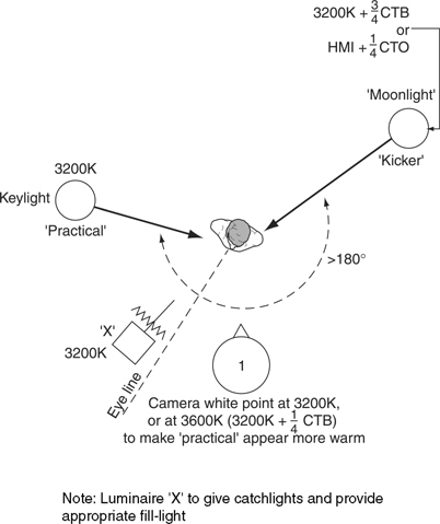
Figure 18.35 Night exterior scene – practical arrangement
Yet another alternative, depending on personal preference, is to reduce the colour temperature difference to half CTB. There will be slight differences in the effect achieved from one manufacturer’s camera to another. Certainly, the older tube cameras had an enhanced Blue response so half-CTB correction was satisfactory. Generally, aim at subtle use of colour; if it is too strong the effect will look too theatrical. Note the use of a kicker as opposed to an offset elevated backlight. A kicker should be at eye level and aimed at the subject’s temple. This reveals more texture on the side of the face and although a ‘cheat’ on reality, generally produces a better result than the elevated backlight.
Important
- The two main lights must be greater than 180° apart to avoid contamination of coloured light.
- For best results avoid symmetrical lighting on the face from the keylight and kicker.
- The small filler light, plus diffusion, provides a catchlight in the eye, it must be positioned to camera left of the eyeline to avoid contamination of coloured light and to maintain good texture on the face. The lighting balance of this light is crucial to the mood created. If only a hint of light around the eyes is required this can best be achieved with a small plastic mirror (e.g. Figure 18.36), or a Dedolight plus projection lens and shutters.
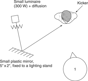
Figure 18.36 Use of a small mirror for dramatic linking of eyes only
If no diffusion is used, the projected image will have a hard edge. The lit area can be reduced by masking off part of the mirror with gaffer tape. This is a much better way of achieving this effect than trying to barndoor a Fresnel spotlight.
- Remember, moonlight should be less intense than the ‘practical’ lights.
- Avoid overexposure: generally exposure will be approximately one stop down on daylight exposure settings.
- Remember that the eye/brain will adapt its ‘white’ point to the prevailing conditions. Consequently, a building lit with an HMI/MSR may not look as blue as you might expect if the eye/brain has adapted to the HMI ‘white’. A yellowish building will, of course, look white!
- Buildings do not need to be lit to high lighting levels, they only need to be made visible. Typically, floodlit buildings are lit to 50-70 lux!
- Ideally, use a waveform monitor, e.g. Hamlet Picoscope, to verify levels or check relative signal levels by flicking to colour bars to re-establish normal levels on the picture monitor.
- It is recommended to experiment with the above ideas to establish your own preference for use of colour, lighting balance and exposure on night shoots.
- Avoid using unfiltered HMI/MSRs to produce moonlight. It tends to produce a very blue coarse look – not subtle enough.
- Remember that when using minimum lighting levels any ambient light may influence your lighting balance.
- When using a mixture of tungsten and HMI/MSR light sources remember HMI/MSRs have three to four times the efficiency of tungsten sources.
When shooting wide shots, typical techniques are:
- using a large HMI/MSR + correction as a single major backlight
- using smoke upstage, backlit with a suitably corrected HMI/MSR
- using the fire brigade to dampen roads, roofs etc. to help reveal texture
- if long shots are required, try to ‘flag’ or barndoor all but one of the lights off the ground to avoid conflicting floor shadows.
Remember that at night a moving subject will not necessarily be lit constantly, but could be lit from ‘practicáis’, e.g. street lights, lights from windows, car headlamps, lights on buildings. A technique to cover periods of walking through unlit areas is to ensure that the artiste is always seen in silhouette. Used by itself, this is another way of introducing ambiguity. Another would be to throw the shadow of the subject onto a building and then shoot the shadow only.
Sodium street lights can be simulated by using ¾CTO on a tungsten source. Use a similar technique to the moonlight set-up, with a (tungsten + ¾CTO) as a kicker to suggest the street light.
Safety at Night
- On a large shoot provide a working light to avoid tripping accidents on cables etc.
- Always have a pocket torch handy for checking camera settings.
- Do not use luminaires so that they are a safety hazard for road traffic, seafarers or aircraft.
18.20 Lighting for Cars
Daylight – Stationary
The major problems in lighting car interiors are:
- Coping with the problems of excessive contrast between the interior of the car and the car exterior (similar to interior subject with back to window).
- Coping with problems of direct sunlight entering the car, again causing excessive contrast problems.
- Lighting the artistes to look right.
Figure 18.37 illustrates one solution to the problem, but how far this lighting plot can be adapted obviously depends on the facilities available. Points to note in the lighting set-up are

Figure 18.37 Lighting a stationary car – daylight
- Except at early morning and late evening the artistes’ faces will not be lit with direct sunlight. They will be lit with a softlight.
- Usually the forehead will not be lit as intensely as the lower part of the face, due to the effect of the top of the windscreen. Hence the use of gaffer tape along the top of the windscreen.
- Use of ND filter on the driver’s window to the cope with excessive daylight outside the car. If 0.6ND is suitable the use of Rosco Scrim could be substituted (provided depth of field not too large) – this is easy to apply.
- Use of an external light to kick the faces from upstage. This helps to preserve the image of being lit from outside, especially if a significant amount of ND filter has been used.
- Use of backlight/kicker. This is especially useful when the upstage artiste looks downstage. It will assist this light if car headrests can be removed.
- Removal of direct sunlight, using an 8 foot x 8 foot butterfly. This may have a silk or black. Black is to be preferred as this will help to keep down the lighting on the downstage artiste. It is imperative that this artiste is not overlit if the total effect is to be believed. An extra black flag may be needed near the open downstage window to help control the lighting on artiste B.
- The correct lighting balance is essential if this is to ‘look right’! If artiste A has to get out of the car, then clearly, when the door is opened the problem of excessive exposure returns. Use of a vertical butterfly with a double black net positioned a short distance upstage of the car door can help with this or alternatively the use of a large sheet of acrylic ND held in a suitable frame.
- With stable natural lighting conditions a similar lighting plot can be created using metallic-based reflectors.
- Note the need for low stands to ensure the lights are at seated eyeline height!
Daylight – Moving
A typical requirement is that of shooting the driver talking to camera, or to the passenger. This has to be achieved without restricting the drivers vision or creating objectionable light sources in the drivers eye-line. A quick solution is shown in Figure 18.38. This uses a battery-operated HMI/MSR 200 W rigged on a magic arm fastened to a vertical ‘pole-cat’. Check that the car roof is suitable for this application and remember to include a clean card (beer mat) between the top of the pole-cat and the car roof! The sun visor is used to support a section of Matthews reflector material. The HMI source is aimed at the Matthews reflector to provide a soft fill-light for the subject. ND filter (or Rosco Scrim) is needed on the car window. Frontal shots of the driver and passenger usually requires the use of the car being mounted on a ‘low-loader’ complete with camera, lighting kit and possibly towing a small generator.
Figure 18.38 Lighting a moving car – daylight
18.21 Cars at Night
Stationary
The principles of lighting a car at night are the same as established earlier for night-lighting:
- Texture
- Ambiguity/clarity
- Colour
- Lighting balance
- Exposure.
Again, a typical requirement is for shooting a two-shot of driver plus passenger. The lighting is set up in Figure 18.39 will cater for close-ups, tight two-shots and wider two shots to include some of the car exterior. The principle is to establish a keylight (1) as 3200 K (camera on 3200 K white balance), with the remaining lights suggesting a ‘night’ feeling by using sources (tungsten+ ½CTB) or (tungsten+ ¾CTB). The lamp marked 2 acts as a kicker to put a blue rim on the driver and passenger. Lamp 3 acts as a backlight but also kicks the downstage side of the driver’s face when he/she turns to the passenger.
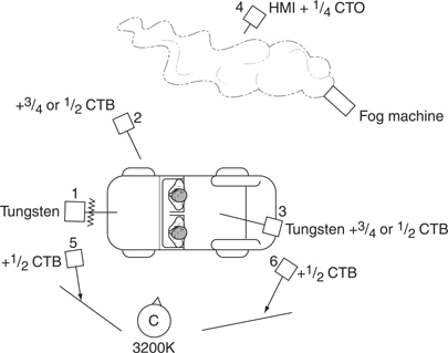
Figure 18.39 Lighting a stationary car interior at night
Lamp 4 is used to backlight smoke to give depth to the shot, or alternatively use an HMI corrected with ¼CTO to light buildings/trees and shrubs for maximum texture. When lighting large flat surfaces beware of large specular reflections if the ‘angles’ are incorrect, i. e. lights reflected directly into the camera lens.
Lamps 5 and 6 are used to provide some lighting for the car exterior and fill-light on the downstage side of the passenger’s face. Soft-light is used for this to avoid specular reflections of the light source on the car bodywork.
This is a set-up which can benefit from experimentation to seek out the options available:
- The keylight is suggested as being from street lamp or a light from a building. It is useful to diffuse this, plus add a strip of gaffer tape along the top of the windscreen to reduce the light on the artiste’s forehead.
- Choice of colour used is down to personal preference from ‘no colour’ to ¾CTB. A useful alternative is white flame green+ ¾CTB or even a pale lavender on tungsten sources, i.e. 3200 K source.
- If possible, remove headrests or use them at the lowest position to avoid a shadow from the kicker (lamp 3).
- Avoid – mutual shadowing of artists
– shadows of artists on the inside of the car
– shadow of the rear view mirror on the artistes, or ‘in-shot’ on the inside of the car.
- Use small wattage lamps, Dedolights or 300 W Fresnel spotlights will work for the main lighting around the car. Lamps 4 will depend on the amount of background to be lit.
- Having established the optimum position of the luminaires and the colour filters to use, the lighting balance and exposure will determine if it ‘looks right’. The lighting balance can be judged by eye and checked on a monitor. Exposure is critical, it is important not to overexpose the picture. As a rough guide expose the picture as though it is a ‘daylight’ scene, note the f-number and then reduce exposure by one f-stop.
Moving Car
With the need to preserve the vision of the driver by not obscuring his view and not blinding him with light, the options available tend to be limited. Small fluorescent lighting kits are available which have small sources (≈6 inches long). These are battery-operated, very compact and lightweight and may be Velcroed into position on the sun visor, and may be powered from the cigarette lighter.
Lighting from below eye-level, as though from the dashboard lights, results in an ‘underlit’ look. Unless specifically requiring this particular look, avoid it! The dashboard light as a light source, with modern cars, is not very convincing!