
Ultrawide Bandwidth Radio Frequency Identification and Localization |
|
CONTENTS
5.2.1 UWB: Definitions and Regulatory Issues
5.2.3 Ranging Capability of UWB Signals
5.3.1 UWB Propagation Characteristics
5.4 UWB RFID and Localization with Active Tags
5.4.3 The IEEE 802.15.4f Standard
5.5 UWB RFID and Localization with (Semi)Passive Tags
5.5.1 Hybrid Tags Based on UHF and UWB Modulations
5.5.2 Tags Based on Backscatter Modulation
5.6.2 High-Accuracy Radio Detection, Identification, and Localization Applications
Radio-frequency identification (RFID) technology for use in real-time object identification is facing a rapid adoption in several fields, such as logistic, automotive, surveillance, and automation systems, etc. [1,2]. An RFID system consists of readers and tags applied to objects. The reader interrogates the tags via a wireless link to obtain the data stored on them. Tags equipped with a complete radio-frequency (RF) transmitter are denoted as active. The cheapest RFID tags with the largest commercial potential are passive or semipassive, where the energy necessary for tag-reader communication is harvested from the reader’s signal or the surrounding environment. In current ultrahigh frequency (UHF) (semi)passive RFID technology, the reader sends an unmodulated continuous wave (CW) field that the tags modulate and scatter back to the reader. The backscatter modulation is realized by properly changing the tag’s antenna load according to the data so that no active RF transmission happens [3].
It is expected that the global revenues coming from the RFID technology will amount to tens of billions of dollars in the near future. This includes many new markets that are being created, such as the market for real-time locating system (RTLS), which will itself be more than $6 billion in 2017 [4]. Therefore, future advanced RFID systems are expected to provide both reliable identification and high-definition localization of tags [5]. Accurate real-time localization at the submeter level, high security, and management of large numbers of tags, in addition to extremely low power consumption, small size, and low cost, will be new important requirements. Unfortunately, most of these requirements cannot be completely fulfilled by the current first- and second-generation RFID [2] or wireless sensor network (WSN) technologies such as those based on the ZigBee standard [6]. In fact, RFID systems using standard CW-oriented communication in the UHF band have an insufficient range resolution to achieve accurate localization, are affected by multipath signal cancellation (due to the extremely narrow bandwidth signal), are very sensitive to narrow-band interference and multiuser interference, and have an intrinsic low security [1,7]. Although some of these limitations, such as security and signal cancellation due to multipath, are going to be reduced or overcome in future versions of UHF RFID systems [8,9], a technology change is required to satisfy new applications’ requirements fully—especially those related to high-definition localization at the submeter level.
A promising wireless technique for future identification and localization systems is the ultrawide bandwith (UWB) technology characterized, in its impulse radio UWB (IR-UWB) implementation, by the transmission of subnanosecond duration pulses. The employment of wideband signals enables the resolution of multipath and extraordinary localization precision based on time of arrival (TOA) estimation signals. In addition, UWB allows for low power consumption at the transmitter side, extremely accurate ranging and positioning capability at the submeter level, robustness to multipath, low detection probability, efficient multiple channel access, and interference mitigation—thus leading to a potentially large number of devices operating and coexisting in small areas [7,10,11].
Thanks to their low power consumption, IR-UWB transmitters can be successfully adopted both for active and passive tags. UWB has been proposed to realize low consumption and low complexity active RF tags for precision asset location systems [12]. Recently, some commercial proprietary RTLSs have been introduced based on tags emitting UWB pulses with extremely low duty cycle to ensure high battery duration [13–15], and the IEEE 802.15.4f working group has been formed to define a dedicated standard to cover the RTLS segment [16].
As anticipated, passive tags solutions are of particular interest thank to their potential lower cost and power consumption. To this purpose, the idea of passive tags based on UWB backscatter signaling was introduced in Dardari et al. [5], Dardari [17], and Dardari and D’Errico [18], where tag architectures as well as backscatter signaling schemes robust to the presence of clutter (i.e., reflections coming from surrounding objects) are presented. Nevertheless, UWB RFID analysis based on backscatter modulation is at the beginning and different issues must still be investigated [5,19].
In this chapter, a survey of the UWB technology and its current application for RFID and RTLS systems is given. Particular emphasis will be paid to recent and promising solutions based on passive UWB RFID tags due to their potential low cost and hence wider market perspectives.
5.2.1 UWB: DEFINITIONS AND REGULATORY ISSUES
The UWB technology has been around since 1960, when it was mainly used for radar and military applications. Nowadays it is a very promising technology for advances in wireless communications, networking, radar, imaging, positioning systems, WSNs, and RFID [6,10,11,20,21].
The most widely accepted definition of a UWB signal is a signal with instantaneous spectral occupancy in excess of 500 MHz or a fractional bandwidth of more than 20% [22]. The fractional bandwidth is defined as B/fc, where B denotes the –10 dB bandwidth and fc is the center frequency. A way to generate such signals is by driving an antenna with very short electrical pulses with duration in the order of 1 ns or less.
In 2002, the US Federal Communications Commission (FCC) issued the First Report and Order (R&O), which permitted unlicensed UWB operation and commercial deployment of UWB devices. There are three classes of devices defined in the R&O document: (1) imaging systems (e.g., ground penetrating radar systems, wall imaging systems, through-wall imaging systems, surveillance systems, and medical systems), (2) vehicular radar systems, and (3) communications and measurement systems. The FCC allocated a block of unlicensed radio spectrum from 3.1 to 10.6 GHz at the maximal effective radiated isotropic power (EIRP) spectral density of –41.3 dBm/MHz for these applications, where each category was allocated a specific spectral mask, as described in reference 22, and UWB radios overlaying coexistent RF systems can operate. In Figure 5.1 an example of an FCC spectral mask for indoor commercial systems is reported. With similar regulatory processes currently under way in many countries worldwide, government agencies responded to this FCC ruling.
Regarding Europe, it is important to mention that on February 21, 2007, the Commission of the European Communities released a decision on allowing the use of the radio spectrum for equipment using UWB technology in a harmonized manner in the community [23]. The decision concerns the use of the radio spectrum on a noninterference and nonprotected basis by equipment using UWB technology, with the definition of maximum allowed EIRP densities in the absence and in the presence of appropriate interference mitigation techniques. In Figure 5.1 the maximum EIRP density in the absence of appropriate mitigation techniques is reported. In particular, the upper frequency band of 6–8.5 GHz has been identified in Europe for long-term UWB operation with a maximum mean EIRP spectral density of –41.3 dBm/MHz and a maximum peak EIRP of 0 dBm measured in a 50 MHz bandwidth without the requirement for additional mitigation [24]. Within the lower band of 3.1–4.8 GHz, low duty cycle (LDC) or interference detection and avoidance (DAA) UWB devices are permitted to operate with the same limits for the EIRP. In addition, dedicated standards have been amended for specific UWB applications such as RTLS [25,26]. Table 5.1 reports an overview of the current worldwide UWB emission masks.
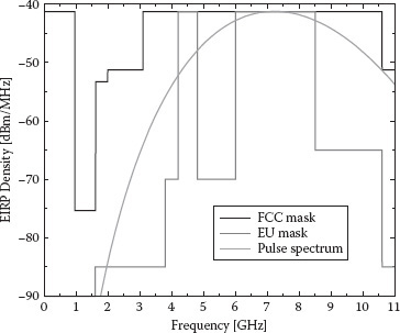
FIGURE 5.1 FCC and EU spectral masks, respectively, for indoor commercial systems in the absence of appropriate mitigation techniques. An example of sixth derivative of the Gaussian pulse spectrum with tp = 0.192 ns, compliant with FCC mask, is also reported.
UWB transmission systems can be realized through conventional modulation schemes by stretching the bandwidth to be larger than 500 MHz, for example, by adopting orthogonal frequency division multiplexing (OFDM) signaling. This approach has been followed by the WiMedia alliance standard for multimedia applications requiring high data rate transmissions [27]. One promising UWB technique, especially for RFID and WSN applications, is named IR-UWB. The IR-UWB technique relies on ultrashort (nanosecond scale) pulses that can be free of sine-wave carriers and do not require intermediate frequency processing because they can operate at baseband, thus drastically reducing the hardware complexity and power consumption. The IR-UWB technique has been selected as the physical (PHY) layer of the IEEE 802.15.4a Task Group for wireless personal area networks (WPAN) low rate alternative PHY layer [20,28], and for the standard IEEE 802.15.4f related to RTLS [16], as will be detailed in Section 5.4.3.
TABLE 5.1
Worldwide UWB Emission Masks
Band |
EIRP |
Mitigation technique |
China |
||
4.2–4.8 GHz |
–41.3 dBm/MHz |
DAA |
6.3–8.9 GHz |
–41.3 dBm/MHz |
No mitigation |
Europe |
||
3.1–4.8 GHz |
–41.3 dBm/MHz |
LDC or DAA |
2.7–3.4 GHz |
–70 dBm/MHz |
No mitigation |
3.4–3.8 GHz |
–80 dBm/MHz |
No mitigation |
3.4–6 GHz |
–70 dBm/MHz |
No mitigation |
6–8.5 GHz |
–41.3 dBm/MHz |
No mitigation |
8.5–9 GHz |
–41.3 dBm/MHz |
DAA |
Japan |
||
3.4–4.8 GHz |
–41.3 dBm/MHz |
DAA |
4.8–7.25 GHz |
–70 dBm/MHz |
No mitigation |
7.25–10.25 GHz |
–41.3 dBm/MHz |
No mitigation |
Korea |
||
3.1–4.8 GHz |
–41.3 dBm/MHz |
LDC or DAA |
7.25–10.25 GHz |
–41.3 dBm/MHz |
No mitigation |
United States |
||
3.1–10.6 GHz |
–41.3 dBm/MHz |
No mitigation |
As said, in IR-UWB the information is encoded using pulses. Typically, the adopted pulse p(t) is derived by the Gaussian pulse p0(t) = exp(−2π(t2/τ2p))
p(t) = 4ν√2π√τp cos ((1 + ν)πt/τp) + sin ((1 − ν)πt/τp)4νt/τp1 − (4νt/τp)2 cos (2πf0t) |
(5.1) |
where parameter τp and roll-off factor ν determine the bandwidth W = (1 + ν)/τp.*
In Figure 5.1 the sixth derivative of the Gaussian pulse with τp = 0.192 ns is shown in the frequency domain. It can be noted that this pulse is compliant with the FCC specifications. In general, due to the short pulse duration (typically less than 1 ns), the bandwidth of the transmitted signal can be on the order of one or more gigahertz.
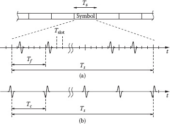
FIGURE 5.2 (a) UWB time-hopping frame structure; (b) UWB direct-sequence frame structure.
To allow for multiuser communication in a typical IR-UWB communication system, each symbol (bit) is associated to multiple pulses.
In time-hopping (TH) schemes, symbols of duration Ts are divided into time intervals Tf called frames (see Figure 5.2a). The frames are further decomposed into smaller time slots Tslot. The UWB pulse p(t), with duration Tp < Tslot, is transmitted in each frame in a slot position specified by a user-specific pseudorandom TH code {ck} having period Ns, where Ns is the number of pulses per symbol [10]. In direct sequence (DS) schemes (see Figure 5.2b), each pulse is modulated according to a pseudorandom binary code {ck} having period Ns and transmitted at regular intervals of Tc seconds—usually named, in this case, chips. The frame/chip time Tf/Tc is usually chosen to be greater than the maximum multipath delay to avoid intersymbol interference. The information can be associated to pulse polarity leading to pulse amplitude modulation (PAM) signaling or to pulse position, thus obtaining a pulse position modulation (PPM) signaling scheme.
Implementing an impulse-based radio allows for a simple circuit structure with low power dissipation since there is no need to up-convert a carrier signal [29]. The transmitter feeds these impulses to a very large bandwidth nonresonating antenna, or sometimes the antenna itself shapes the pulses to the required frequency of operation. In Figure 5.3 an example of a simple UWB pulse generator schematic proposed in Baghaei-Nejad et al. [29] is reported; it consists of a delay line, a NOR gate, and a pulse shaping circuit.
The basic UWB receiver is a correlation receiver [10] where the received signal is correlated with a local replica (template) of the transmitted pulse p(t) or, equivalently, is filtered by a filter matched to p(t) (matched filter [MF]). In a single-user additive white Gaussian noise (AWGN) scenario, the bit error probability (BEP) of a UWB link employing binary antipodal PAM is simply
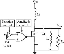
FIGURE 5.3 Example of UWB transmitter schematic [29].
(5.2) |
where Er is the energy of the received pulse, N0 is the thermal noise one-side power spectral density, and erfc(·) is the complementary error function. The received energy per symbol is Es = NsEr.
Typical indoor environments often exhibit the presence of a dense multipath with delay spread much larger than the resolution capability of the signal being employed [30,31]. The transmission of ultrashort pulses can potentially resolve extremely large numbers of paths experienced by the received signal, especially in indoor environments, thus eliminating significant multipath fading [30]. This may considerably reduce fading margins in link budgets and may allow low transmission power operation. In addition, rich multipath diversity can be collected through the adoption of rake receivers, which combine the signals coming over resolvable propagation paths in a way that maximizes the signal-to-noise ratio (SNR) [32].
It can be shown that the bit error probability of a rake receiver is
(5.3) |
where ηcap is called the energy capture efficiency and accounts for the ability of the RAKE receiver to collect the energy coming from different propagation paths. For more information on the fundamentals of UWB, we refer to references [10], [11], and [32] and references therein.
5.2.3 RANGING CAPABILITY OF UWB SIGNALS
Distance estimation (ranging) between tags and multiple readers represents the first step to localize the tag using, for example, multilateration algorithms [33]. Considering that the electromagnetic (e.m.) waves travel at the speed of light c = 3 · 108 m/s, the distance estimate can be obtained from the measurement of the time of flight (TOF) τf of the signal and by observing that τf = d/c, where d is the actual distance between the tag and the reader. This requires an accurate estimation of the TOA of the received signal.

FIGURE 5.4 Classical MF-based TOA estimator.
To understand which fundamental system parameters dominate ranging accuracy, we present an overview of the performance limits of TOA estimation in AWGN channels. We consider a scenario in which a unitary energy pulse p(t) is transmitted (with duration Tp) through an AWGN channel.* In the absence of other error sources, the received signal can be written as
(5.4) |
where Er is the received energy and n(t) is AWGN with zero mean and two-sided power spectral density N0/2.
The goal is to estimate the TOA τ, and hence the distance d, by observing the received signal r(t). This task can be challenging due to the presence of thermal noise and multipath components. Under this simple model, TOA estimation is a classical nonlinear parameter estimation problem, with a solution based on an MF receiver [34]. As shown in Figure 5.4, the received signal is first processed by a filter matched to the pulse p(t) or, equivalently, by a correlator with template p(t). The TOA estimate is given by the time instant corresponding to the maximum absolute peak at the output of the MF over the observation interval. This scheme yields a maximum likelihood (ML) estimate, which is known to be asymptotically efficient; that is, the performance of the estimator achieves the Cramér-Rao bound (CRB) for large SNRs.†
The MSE of any unbiased estimate ˆd
Var (ˆd) = E {∈2} ≥ c28π2 B2eff SNR |
(5.5) |
where ∈ = ˆd − d
B2eff = ≜ ∫∞−∞f2 |P(f)|2 df∫∞−∞ |P(f)|2 df. |
(5.6) |
Notice that the lower bound in (5.5) decreases with both SNR and the constant Beff, which depends on the shape of the pulse. This reveals that signals with high power and/or wide transmission bandwidth are beneficial for ranging.
It is known that the ML estimation error tends asymptotically to the Gaussian distribution. Denoting d the true distance, the measured range ˆd
(5.7) |
where the ranging estimation error ∈ can be modeled, as first approximation, as a Gaussian random variable (RV) with zero mean and variance σ2, where σ2 is bounded by (5.5).
Figure 5.5 shows the root mean square error (RMSE) for CRB using the RRC second and sixth-order Gaussian monocycle pulses. Note that higher derivative Gaussian monocycles or lower τp reduce the bound. It can be observed that centimeter level accuracy (e.g., RMSE on TOA less than 1 ns) is potentially feasible using UWB signals. Other improved but more complex bounds can be found in Dardari et al. [34].
In more realistic environments, numerous practical factors might affect ranging accuracy. Sources of error from wireless signal propagation include multipath, direct path excess delay and blockage incurred by propagation, respectively, of a partially obstructed or completely obstructed direct path component that travels through obstacles such as walls in buildings. For more information about ranging using the UWB signal, please refer to Dardari et al. [34] and references therein.
5.3.1 UWB PROPAGATION CHARACTERISTICS
The performance limits of a communication or localization system are determined by the channel it operates in. UWB propagation channels show fundamental differences from conventional narrowband propagation in many respects. In
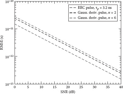
FIGURE 5.5 CRB on the TOA estimation RMSE as a function of SNR in an AWGN channel. The RRC pulse, the second-order Gaussian, and the sixth-order Gaussian monocycle pulses with, respectively, tp = 3.2 ns, tp = 1 ns, and tp = 0.192 ns are considered.
this section a brief description of UWB propagation characteristics and models is presented.
In a free space environment the received signal power spectral density at distance d is
Pr (f) = Pt (f) Gt (f) Gr (f)c2(4πfd)2 |
(5.8) |
where Pt(f) is the power density spectra of the transmitted signal; Gt(f) and Gr(f) are the transmit and receive antenna power gains, respectively; and c is the speed of light.
A number of UWB channel models have been proposed depending on the frequency range and operating conditions [30–32,35]. Widely adopted models valid for the 3–10 GHz frequency range in a number of different environments as well as for the frequency range below 1 GHz in office environments have been presented within the IEEE 802.15.4a Task Group and are briefly described in the following [31,35,36].
5.3.1.1 Path-Loss Model
In a UWB channel, the path loss is a function of frequency, distance, and the frequency characteristics of the antennas. In Molisch et al. [31], the following frequency-dependent path-loss model is given:
L0 (f,d) = 2k0 (f/fc)2(κ + 1) dβηTX (f) ηRX (f), |
(5.9) |
where
k0 is the isotropic path-loss at the reference distance of 1 m and center frequency fc
the parameter κ is the frequency dependency decaying factor
ηTX(f) and ηRX(f) are, respectively, the transmit and the receive antenna efficiencies
fc is the center frequency usually taken equal to 5 GHz.
Parameter β is the power path-loss exponent typically ranging between ≈1.8 and ≈4 [36], while the coefficient 2 accounts for the typical loss due to the presence of a person close to the antenna.
5.3.1.2 Multipath Characterization
Most of UWB channel models are based on an extended version of the classical Saleh-Valenzuela indoor channel model [37], where multipath components arrive at the receiver in groups (clusters) following the Poisson distribution. Specifically, the equivalent baseband channel impulse response related to the IEEE 802.15.4a models is [31]
h0(t) = L∑l=1Kl∑k=1 αk,l exp (j θk,l) δ(t − Tl − τk,l), |
(5.10) |
where
L represents the number of clusters
Kl is the number of paths in the lth cluster
Tl is the TOA of the lth cluster
αk,l, θk,l, and τk,l represent, respectively, the amplitude, phase, and relative excess delay associated with the kth path within the lth cluster
δ(t) is the Dirac pseudofunction
The IEEE 802.15.4a working group defined several models based on (5.10), denoted with CM1-CM8, whose parameters’ statistical characterization is specific to different reference environments (e.g., open office, industrial, etc.).
Another widely adopted model is the dense multipath model with a single cluster composed of L independent equally spaced paths and exponential power delay profile (PDP). The passband impulse response is given by
(5.11) |
where αl = alpl, with al being the path amplitude and pl an RV that takes, with equal probability, the values {–1,+1} [30]. The average path power gains Λl are given by
Λl = E {|αl|2} = (eΔ/ε − 1) e−Δ(l−1)/εeΔ/ε(1 − eLΔ/ε) |
(5.12) |
for l = 1, 2, … , L. The parameter ε describes the multipath spread of the channel (decay time constant) and Δ is the resolvable time interval so that the lth path arrival time is τl = τ1 + (l – 1)Δ. In most of the previously mentioned models the small-scale fading, which characterizes the path amplitudes al or αk,l, follows a Nakagami-m distribution, with m being the severity parameter depending on the working conditions.
As already mentioned, passive RFID tags are based on backscatter modulation, where the antenna reflection properties are changed according to information data [3]. It is therefore fundamental to model the backscatter antenna characteristics. In general, when an e.m. wave encounters an antenna, it is partially reflected back depending on antenna configuration. An antenna scattering mechanism is composed of structural and antenna mode scattering [38,39].* Structural mode occurs owing to the antenna’s given shape and material and it is independent of how the antenna is loaded. On the other hand, antenna mode scattering is a function of the antenna load; thus, data can be sent back to the reader through a proper variation of the antenna load characteristic without requiring a dedicated power source (backscatter modulation). This property is currently adopted in traditional passive UHF RFID tags based on CW signals to carry information from the tag to the reader [3].
While in UHF RFIDs an extensive literature exists dealing with this issue [3,39], the characterization of backscatter properties when operating with UWB signals is still not a well investigated and understood topic, especially in realistic environments [40–41,42,43]. In the following I give an overview of the UWB antenna backscatter properties.
5.3.2.1 UWB Antenna Backscattering
When a UWB pulse is transmitted and UWB antennas are employed, the reflected signal takes the form reported in Figure 5.6, where the structural and antenna modes’ scattered components are plotted separately for convenience. The antenna mode scattered signal can be varied according to the antenna load ZL, whereas the scattering of the structural mode will remain the same. Among the various possibilities, three particular choices are of interest for passive UWB RFID: ZL = 0 (short circuit), ZL = ∞ (open circuit), and ZL = Z∗A

FIGURE 5.6 Example of backscatter mechanism of the transmitted pulse due to tag’s antenna and the presence of scatterers [44].
5.3.2.2 The Round-Trip Channel Transfer Function
To analyze the performance of backscatter modulation schemes, a proper model for the reader–tag–reader interaction is needed.
Consider a reference scenario, as shown in Figure 5.6, where a couple of UWB antennas, acting as tag and reader and located at distance d, are present. In the simple case of linear polarization of each antenna, the far field radiated from the reader and incident to the tag can be expressed as
Einc (f; d,Θr) = e−kdd. √η04π. HTreader (f; Θr). a1 (f) , |
(5.13) |
where
λ is the wavelength
k = 2π/λ
η0 is the free space impedance
a1(f) is the incident wave at the reader’s port
Θr = (θreader,ϕreader) is the reader orientation
HTreader (f; Θr)
The e.m. wave at the tag’s antenna is partially backscattered according to the antenna’s scattering characteristics, which depend on the antenna load (different load configurations will be referred to as tag status X) and reader–tag orientation in the three-dimensional space Θ = {Θr, Θt}, with Θt = (θtag,ϕtag) being the tag orientation. The antenna mode component of the received backscatter signal at the reader’s antenna port is given by
b1 (f; d, X, Θ) = HRreader (f; Θr). √4πη0. E(a)SC (f; d, X, Θ), |
(5.14) |
where HRreader (f; Θr)
Htag (f; Θ, X) = 4πdλ . E(a)SC (f; d, X, Θ).ej kdEinc (f; d,Θr). |
(5.15) |
In particular, it can be shown that the amplitude characteristic of Htag(f;Θ,X) can be expressed as
|Htag (f; Θ, X)| = √4πσ(f; Θ, X)λ2 , |
(5.16) |
where σ(f;Θ,X) is the radar cross section of the tag. It turns out that the tag transfer function depends on the reader and local tag orientation Θ, but it is not dependent on the distance, since it relates the incoming plane wave complex amplitude at the tag to the far field radiated spherical wave. It is, for example, easy to prove that Htag(f;Θ,X) = 1 for a lossless tag reradiating isotropically. By considering the relationship between the transmitting and receiving modes of the reader
HRreader (f; Θr) = −J λ4π HTreader (f; Θr), |
(5.17) |
we finally obtain the round-trip transfer function for linear polarized antennas:
Note from (5.18) that, in free-space propagation conditions, the channel gain decreases with the distance d of an exponent factor of 2 instead of 1, as happens in conventional communication links. This typically reflects into a poor link budget when using the backscatter principle for data communication.
In a UWB RFID system the reader’s antenna emits typically a very short pulse p(t). We denote w(t;d,X,Θ) the backscattered signal, received back by the reader’s antenna, because of the tag’s antenna mode, shape and energy of which are a function of the tag status X (open, short, loaded) as well as of Θ. In the frequency domain, it is
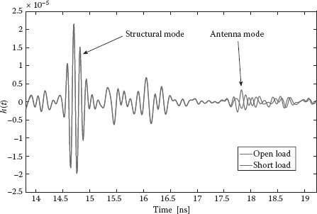
FIGURE 5.7 Example of backscatter impulse responses collected inside in the anechoic chamber at distance dref = 2.15 m for open and short circuit load conditions.
W (f; d, X, Θ) = P(f) H (f; d, X, Θ). |
(5.19) |
Figure 5.7 shows an example of backscattered signal measured in the anechoic chamber for open- and short-load conditions. In order to discriminate the structural mode from the antenna mode easily in the time domain, a delay line of electric length 40 cm was inserted between the tag antenna and the load. The structural and antenna modes can be clearly distinguished, where only the latter depends on the antenna load. In particular, the difference of about 180° for the antenna mode scattering between the two load conditions is clearly evident.
In a more realistic scenario, where several scatterers might be present, H(f;d,X,Θ) must also account for multipath components arising due to reflections. As of now, the only statistical model for a UWB backscatter round-trip channel with multipath available in the literature is that adopted in Sibille et al. [42] and Heiries et al. [46], where a double-convoluted IEEE 802.15.4a channel model based on (5.10) is proposed. However, this preliminary model has not been validated yet through extensive experimental campaigns in realistic scenarios.
5.3.2.3 Measurement Results
We present some experimental results collected in a typical laboratory scenario having dimensions 5.13 × 4.49 m2 at ENSTA-ParisTech laboratory. A rectangular grid of nine test points as shown in Figure 5.8, spaced out of about 1 m in depth and 70 cm in width, was defined. The tag monopole dual feed stripline (DFMS) antenna was positioned alternatively in each point on a vertical support dressed with absorbers. Data postprocessing was performed to obtain the antenna backscattering response from the measured parameter S21 = H(f;d,X,Θ).

FIGURE 5.8 Indoor scenario considered for the measurement campaign at ENSTAParisTech. The distances between each point and the antennas connected to the vector network analyzer are also reported.
In Figure 5.9(a), an example of backscattered signal h(t;d,X,Θ) measured in the laboratory scenario from the tag placed at location I (distance 3.15 m) is reported. As can be noted, several clutter components (including the antenna structural mode) are present. Figure 5.9(b) shows the antenna mode backscattered signal (of interest) after clutter removal. Owing to its small amplitude, it turns out to be completely buried within the clutter component. The presence of an echo received after the first direct path is also clearly seen and can be ascribed to indirect paths between the tag and the reader. In most of the considered configurations, the normalized cross correlation between the backscattered signals in the case of open- and short-circuit loads is close to –1, as expected for antenna mode signals. This good symmetry property is useful in cases of signaling schemes employing antipodal pulses and justifies, in the following analysis, the approximation of perfect pulse symmetry—that is, w(t) = w(t;d,0,Θ) = –w(t;d,1,Θ), where for notation compactness, we have hidden in w(t) the explicit dependence on d and Θ.
In Sibille et al. [42] and Guidi et al. [47], extended measurement results in a realistic environment are presented. An important issue to be investigated is the characterization of the effect of close-to-antenna objects. Some interesting preliminary results can be found in Guidi et al. [43], where it is shown how near metallic objects do not lead, in general, to a backscattered signal reduction—contrary to what happens in narrowband UHF RFID tags.

FIGURE 5.9 Example of backscatter responses collected inside the laboratory (plot a) grid location I at distance of 3.15 m, and of the only antenna mode contribution after clutter removal (plot b) in the same location I.
5.4 UWB RFID AND LOCALIZATION WITH ACTIVE TAGS
As already mentioned, an IR-UWB transmitter can be very simple and it is characterized by an extremely low duty cycle transmitted signal. Therefore, such a transmitter has low complexity and low consumption (less than 10 mW, depending on the pulse repetition rate) [49,50]. On the other hand, a UWB receiver, even a simple one, is typically characterized by higher values of consumed power that could be in the order of 100 mW [49]. Therefore, devices based on the IEEE 802.15.4a standard for WSNs, which allows for bidirectional communication, do not fit typical RFID applications requirements. For this reason most of proposed UWB RFID devices designed for RTLSs have only transmitting active tags operating with low duty cycle in order to extend battery operation up to a few years [12–15].
An alternative solution has been proposed [48] where the concept of pseudorandom active reflector is introduced. As shown in Figure 5.10, it consists of a simple device that repeats a slightly delayed version of the received UWB signal only in certain time intervals according to a suitable pseudorandom (PR) TH sequence. In particular, the signal received by the antenna is amplified with gain G and delayed by a fixed quantity Td of a few nanoseconds. The delayed version of the signal is used to drive the transmitter section composed of a power amplifier and a UWB antenna. The trigger pulse at the output of the PR generator enables the receiver amplifier for a certain time window Tw (activity window). A delayed version, by the quantity Td, of the same trigger pulse is used to enable the transmitter. The transmission and receiving windows are not time overlapped, so no transmitter–receiver coupling occurs and the same antenna can be used for both the transmitter and receiver. The reader emits pulse trains with the same PR TH sequence used by the reflector it wants to communicate with. Each reflector has a unique PR sequence and reflects, with a delay Td, the received UWB signal for a short time interval according to the TH sequence (see Figure 5.10). When synchronized, all transmitted pulses are reflected only by the tag adopting the same PR sequence of the reader, thus making the reader able to collect coherently the energy from that particular tag. As stated in Dardari [48], the advantages of this solution are in the hardware simplicity since only the analog section is present, in the low power consumption of the tag, and in the low timing constraint regarding the relative transmitter and reflector clock rates.

FIGURE 5.10 Pseudorandom active UWB reflector scheme and example of timing structure in case of single-pulse transmission [48].
The first application of UWB technology in the RFID and RTLS fields was for precision asset location systems operating in indoor environments [12–15]. In these systems only UWB transmitting tags are employed; then, tag position estimation cannot rely on absolute distance estimate between tag and readers and localization schemes based on time difference of arrival (TDOA) are usually adopted. In TDOA-based localization systems, burst UWB signals are broadcast periodically by the tag and are received by several readers placed in known positions (see Figure 5.11a). The readers share their estimated TOA and compute the TDOA, provided that they have a common reference clock. Considering that time measurement accuracy should be in the order of 1 ns or less, readers must be kept tightly synchronized through a wired network connection. To calculate the position of the tag, at least three readers with known position and two TDOA measurements are required. Each TDOA measurement can be geometrically interpreted as a hyperbola formed by a set of points with constant range differences (time differences) from two readers [33].
Time Domain Plus RTLS is an example of a commercial proprietary system designed for locating personnel or mobile assets adopting the TDOA technique [13]. The active tag is a compact IR-UWB battery powered transmitter that is designed for long battery duration, up to 4 years (at 2 Hz update rate) or up to 1.5 years (at 4 Hz update rate). The system can locate and track thousands of tags with submeter location accuracy using an adequate number of tightly synchronized readers that perform the functions of receiving tag signals, demodulating the tag data, measuring the TOA for each tag, and computing the TDOA for location estimation.
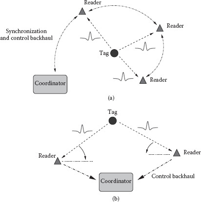
FIGURE 5.11 Active tag localization using (a) TDOA and (b) AOA estimation techniques.
Another possibility to localize the tag is to measure the angle of arrival (AOA) of the signal, thus obtaining the information about tag direction to neighboring readers (see Figure 5.11b). The AOA of an incoming radio signal can be estimated by using multiple antennas with known separation (antenna array) and by measuring the TOA of the signal at each antenna. Given the differences in arrival times and the array geometry, it is possible to estimate the direction of propagation of a radio-frequency wave incident on the antenna array. AOA does not require the precise time synchronization needed for TOA and TDOA techniques. Two angle measurements are required to determine node position (triangulation) [33]. In non-line-of-sight (NLOS) environments, the measured AOA might not correspond to the direct path component of the received signal and large angle estimation errors can occur. Due to the presence of multiple antenna elements, AOA techniques are in general more expensive in terms of cost and device dimensions than TDOA-based techniques.
The Ubisense platform is an example of a commercial precision localization system where active tags are localized using TDOA or AOA techniques [14]. When AOA localization is performed, no tight synchronization among readers is required, thus drastically reducing network requirements. However, the positioning accuracy is less than that obtainable using TDOA measurements.
Zebra Enterprise Solutions commercializes its RTLS, called Sapphire DART [15]. The location system is TOA- or TDOA based, the tag emits in the 6.5 GHz band, and the blink rate is similar to that of Ubisense at a few hertz.
5.4.3 THE IEEE 802.15.4f STANDARD
The IEEE 802.15.4f Active RFID System Task Group is chartered to define new wireless PHY layers and enhancements to the 802.15.4-2006 standard medium access control (MAC) layer [16]. This amendment defines a PHY layer, and only those MAC modifications required to support it, for active RTLS. It allows for efficient communications with active tags and sensor applications in an autonomous manner in a promiscuous network, using very low energy consumption (low duty cycle) and low transmitter power. The PHY layer parameters are flexible and configurable to provide optimized use in a variety of active tag operations including simplex and duplex transmission (reader to tags and tag to readers), multicast (reader to a select group of tags), unicast (reader to a single tag), tag-to-tag communication, and multihop capability.
At the time of writing, the group achieved a common proposal on the PHY layer based on three different physical sublayers, respectively: UWB and UHF at 433 MHz and 2.4 GHz. The UWB PHY is based on the on/off keying (OOK) modulation with 1–2 MHz pulse repetition frequency enabling high-accuracy TOA-based ranging.
The UHF interface is in the frequency range of 433.05–434.79 MHz and 1.74 MHz bandwidth. The modulation is minimum shift keying (MSK) with data rates of 250 Kb/s or 31.25 Kb/s. A received signal strength indicator is used as a low accuracy location determination mechanism.
The 2.4 GHz air interface is built on the IEEE 802.15.4 standard PHY layer. It could be used to stand alone for low precision RTLS or to provide assistance to UWB PHY layer. The operating bands have been chosen in order not to affect Wi-Fi and Zigbee nearby devices. Again, the MSK modulation is used with a bit rate of 250 Kbps found as a compromise between range, bandwidth, and power consumption.
The PHY layer specification supports a large tag population (hundreds of thousands) and basic functionalities such as read and write with authentication and accurate localization. The communication reliability of the system is expected to be high for applications such as active tag inventory counting or auditing, high-value asset location tracking, and personnel tracking. Typical requirements are operation in dense, metallic environments with submeter localization accuracy; real-time presence and location updates in seconds; and small tag sizes for easy placing on typical high-value assets. The active IEEE 802.15.4f PHY layer is capable of working in the presence of interference from other devices operating within the band of operation.
5.5 UWB RFID AND LOCALIZATION WITH (SEMI)PASSIVE TAGS
When tag cost, size, and power consumption requirements become particularly stringent, passive or semipassive tag solutions have to be taken into consideration. As already mentioned, communication with passive tags usually relies on backscatter modulation even though the tag’s control logic and memory circuits must still be energized in order to have the tag working properly. Typically, passive RFID tags obtain the necessary power to operate from the RF signal sent by the reader. As a consequence, in conventional UHF RFID systems, the corresponding operating range is restricted to be no more than 7–8 m with a transmission power level of 2–4 W [3]. Unfortunately, due to regulatory constraints, the transmission power allowed for UWB devices is below 0 dBm. This means that no sufficient power can be derived from the received UWB signal to power up a remote tag at significative distance. A possible solution is represented by hybrid tag architectures, as will be illustrated in Section 5.5.1.
Besides the adoption of semipassive tags with battery-powered control logic, a promising possibility to retrieve the necessary energy is to use energy scavenging techniques that, in many cases, provide sufficient power (about 1–10 μW) for the control logic [51]. An interesting alternative is represented by chipless tags characterized by the absence of any control logic circuit, as will be illustrated in Section 5.6.
5.5.1 HYBRID TAGS BASED ON UHF AND UWB MODULATIONS
Hybrid tags solutions are proposed in references [29] and [52–53,54,55]. The main idea is to have an asymmetric link where in the downlink (reader–tag) a conventional transmission protocol at UHF is adopted to power up the tag and accumulate enough energy to allow an IR-UWB transmitter to send data for a short time interval at high data rate in the uplink (tag–reader).
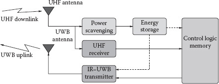
FIGURE 5.12 Hybrid UWB tag architecture proposed in Baghaei-Nejad et al. [29].
The block diagram of the module proposed in Baghaei-Nejad et al. [29] can be seen in Figure 5.12. It consists of a UHF receiving antenna, a power scavenging unit, an energy storage unit (basically a big surface-mounted capacitor), a UHF receiver, a low power IR-UWB transmitter, a UWB transmit antenna, and the control logic. Similarly to conventional passive tags, the incoming RF signal transmitted by the reader at UHF is used to provide power supply and receive the data. In particular, the reader radiates the RF signal with no data for at least 7 ms, which is the time for full charge of the storage capacitor. After enough energy has been collected, the tag goes to the receiving mode to receive commands from the reader at a low data rate (40 Kbps). The uplink transmission is performed using the IR-UWB transmitter. Thanks to the high transmission data rate (1 Mbps with Ns = 10 pulses per bit) and the low transmitter consumption (64 μW), the energy stored in the capacitor is sufficient to allow the transmission of packets containing more than 128 bits. Circuit implementation and simulations have shown that up to 10.7 m operating range with 4 W EIRP emission is feasible from the energy budget point of view. Unfortunately, no results are reported by the authors related to the uplink data transmission performance and the associated operating range.
Remote powering of a passive UWB tag by UHF has recently been achieved for high data rate exchanges (>50 Mbits/s at a few tens of centimeters) from a cell phone to a tag embedding a large memory [54].
5.5.2 TAGS BASED ON BACKSCATTER MODULATION
Recently, some applications of the UWB technology in tags based on backscatter modulation have been proposed [5,17,18,44,56,57]. Due to its extremely low complexity, backscatter communication appears very promising, especially in the perspective of the adoption of efficient energy scavenging techniques for a tag’s control logic alimentation. For this reason, in the following I describe more details to this solution.
In Figure 5.13 the architectures proposed in reference [17] and analyzed in references [18], [44], [47], and [57] for tag and reader are reported. The reader is composed of a transmitter and a receiver section.
During the interrogation cycle, the reader transmits a sequence of UWB pulses modulated by a periodic binary spreading sequence {dn} of period Nc with dn ∈ {–1,1} specific to that particular reader (reader’s code). In general, Npc pulses are associated to each code symbol (chip). To accommodate the signals backscattered by tags corresponding to an entire packet of Nr bits, the UWB interrogation contains Nt = NrNs pulses, where Ns = NcNpc is the number of pulses associated to each bit. Pulses are separated by Tp seconds. Then the UWB transmitted signal takes the form of
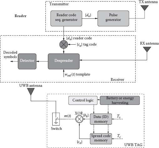
FIGURE 5.13 The considered scheme of the tag and the reader composed of a transmitter and a receiver section [18].
sreader (t) = Nr−1∑k=0s (t − kNcTc) |
(5.20) |
This is characterized by a transmission power Pt, where Tc = NpcTp is the chip time, s(t) is the composite sequence
s (t) = Nc−1∑n=0dn g (t − nTc), |
(5.21) |
and
(5.22) |
is the waveform associated to each chip dn composed of Npc elementary UWB pulses p(t). The pulse repetition period Tp is chosen so that all signals backscattered by the environment are received by the reader before the transmission of the successive pulse. In the indoor scenario, Tp = 50–100 ns is usually sufficient to this purpose.
Each pulse in (5.20) is backscattered by the tag’s antenna as well as by all the surrounding scatterers present in the environment, which form the clutter component.
The main task of the receiver section of the reader is to detect the useful backscattered signal (i.e., that coming from the tag’s antenna mode scattering, which depends on antenna load changes) from those backscattered by the antenna structural mode and other scatterers (clutter), which are, in general, dominant. To make the uplink communication robust to the presence of clutter and interference, and to allow multiple access, a proper backscatter modulation strategy is necessary at tag side.
In Figure 5.13, an example of tag architecture employing a binary backscatter modulator composed of a UWB switch is shown. The switch is controlled by a microcontroller; its purpose is to change the switch status X (short or open circuit) at each chip time Tc according to the data to be transmitted and a zero mean (balanced) periodic tag’s code {cn}, with cn ∈ {–1,+1}, of period Nc [17,18,46]. Specifically, each tag information bit bk ∈ {–1,+1} is associated to Ns pulses; thus, the symbol time results Ts = TcNc = TpNs, as illustrated in Figure 5.14. In this way the polarity of the reflected signal changes according to the tag’s code during a symbol time, whereas the information symbol affects the polarity of all pulses composing the sequence each symbol time. Therefore, the backscatter modulator signal, commanding the tag’s switch, can be expressed as
m (t) = Nr−1∑k=0bk Nc−1∑n=0cn Π (1Tc (t − nTs − iTc − Δ)) |
(5.23) |
having defined Π(t) ≜ 1 for t ∈ [0,1] and 0 otherwise. Note that, in general, reader and tag have their own independent clock sources and hence they have to be treated as asynchronous. Then the tag’s code {cn} is not in general time aligned to the reader’s code {dn}. The parameter Δ in (5.23) denotes the clock offset of the tag with respect to the reader’s clock.
Powerful acquisition techniques [58] and the TOA estimator robust to clutter proposed in Xu and Law [59] can be adopted at a reader’s side to compensate for clock offset. Once the tag and reader codes are aligned and the TOA is estimated, the reader can adjust its internal clock so that it becomes synchronous to that of the intended tag. A more general analysis considering asynchronous multiple tags can be found in Dardari et al. [44] and in [66]. For the sake of illustration, in the following I refer to a single tag scenario and consider perfect synchronization between reader and tag (i.e., Δ = 0). In addition, the tag response due to the antenna mode is examined, whereas the antenna structural mode will be treated as part of the clutter, since it does not depend on data symbols. As a consequence, any clutter removal technique adopted will be effective on the antenna structural mode component as well.
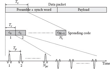
FIGURE 5.14 Example of backscattered signal structure. Only useful component reported.
Considering perfect backscattered pulse symmetry—that is, w(t;0,d,Θ) = –w(t;1,d,Θ) ≜ w(t)—the received signal at the reader can be expressed as [44]
where n(t) is the AWGN with two-sided power spectra density N0/2, and the signal w(t) represents the backscattered version of the pulse p(t) when short-circuit load is applied to the antenna, which is in general distorted due to antennas and channel frequency selectivity. The signal w(c)(t) represents the backscattered version of the pulse p(t) due to the clutter component, which also accounts for pulse distortion and tag antenna structural mode.
Looking at (5.24), it can be noted that only the antenna mode scattered component results modulated by the combination of the tag’s and reader’s codes {cn} and {dn}, whereas all clutter signal components (including the antenna structural mode scattering) are received modulated only by the reader’s code {dn}. This property can be usefully exploited to remove the clutter component through a proper receiver and code design.
An example of a possible receiver scheme is that reported in Figure 5.13, where a correlator-based demodulator is adopted with a template:
sref (t) = Nc−1∑n=0dn cnNpc−1∑i=0wref (t − iTp − nTc). |
(5.25) |
The optimum receiver can be obtained ideally by choosing the waveform wref(t) = w(t) (perfect matched receiver) as pulses composing the local template in the correlator. Unfortunately, in practical situations, wref(t) ≠ w(t); we indicate with ρ the normalized cross correlation between the actual received pulse w(t) and the template wref(t), which accounts for the mismatch due to pulse distortion (note that ρ = 1 in cases of perfectly matched receivers). In substance, this scheme performs a de-spreading operation using the combined code {cn · dn}, which identifies both the reader and the desired tag.*
Every Ts seconds, the output of the correlator is sampled, thus obtaining the decision variable for the kth bit bk:
yk = bk Er ρ Ns + γ(c) (kTs) Nc−1∑i=0ci + zk, |
(5.26) |
where zk is the thermal noise sample with variance
σ2z = N02 Ns
and Er represents the average received energy per pulse. Using (5.19) Er is given by
(5.27) |
As can be deduced from (5.26), to remove the clutter component completely, it is sufficient that the tag’s code {cn} has zero mean; that is,
∑Nc−1n=0 cn = 0.
In such a case (5.26) can be further simplified, leading to
(5.28) |
In general, from (5.28), it is easy to show that the BEP is given simply by
Pb = 12 erfc (√Er Ns ρ2N0) . |
(5.29) |
For further convenience, we define Gref the round-trip channel power gain at the reference distance dref and at the maximum direction of radiation Θmax in the AWGN scenario. In addition, we assume a typical exponential path-loss law where the power path-loss exponent β usually ranges between ≈1.8 and ≈4 [36]. The BEP can be rewritten as [18]
Pb = 12 erfc (√Pt Gref ρ2 (drefd)2βN0 Rb) , |
(5.30) |
where Rb = 1/(NsTp) is the data rate (bit rate). It is interesting to note that the exponent 2β is present in (5.30), instead of β, to account for the two-way link.
5.5.2.1 Performanes Analysis in Anechoic Chamber
We now investigate the potential operating range of the passive UWB RFID system described in this section considering the following parameter values: Tp = 100 ns, F = 4 dB (receiver noise figure), and EIRP = –6.7 dBm. The FCC-compliant sixth derivative Gaussian monocycle has been considered for the transmitted pulse.
Figure 5.15 shows the achievable operating range as a function of the data rate Rb for a fixed target BEP Pb = 10−3. A perfectly matched receiver in anechoic chamber scenario (AWGN channel) is considered using measurement data for different tags’ antenna orientation offsets ϕ with respect to the maximum radiating angle. For each measured data set, the normalized cross-correlation coefficient ρ was calculated and used in (5.30). For the balanced antipodal Vivaldi (BAV) antenna considered in the measurements, Gref = –75 dB, which accounts also for the reader’s antenna gain Greader = 5 dB. From the figure, it can be seen that, for example, for data rate Rb = 103 bits/s, an operating range larger than 20 m can be achieved. However, antenna radiation pattern and pulse distortion might determine a significant performance degradation when devices are not oriented to the maximum radiating direction, as can be noted in Figure 5.15 (see curves with ϕ ≠ 0). For comparison, the corresponding operating ranges in free-space conditions are reported for UHF-passive RFID tags operating at 868 MHz and 2.4 GHz, respectively, with a transmitted EIRP of 500 mW according to European regulations [60]. As can be noted, using the UWB technology, a significantly larger operating range is achievable with respect to that of UHF-based RFID systems, especially for low data rates, with a dramatically reduced transmitted power level (≈0.09 vs. 500 mW).
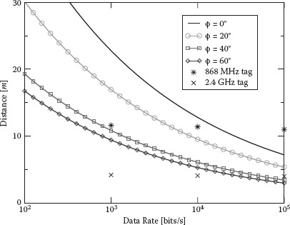
FIGURE 5.15 Tag–reader operating range in meters as a function of the data rate for Pb = 10−3 and different tag orientations in the anechoic chamber scenario [44]. BAV antenna for the tag is considered. Cross and star dots refer to the corresponding performance of UHF tags operating at 868 MHz and 2.4 GHz, respectively. (From G. D. Vita and G. Iannaccone. IEEE Transactions on Microwave Theory and Techniques, vol. 59, no. 9, pp. 2978–2990, Sept. 2005.)
5.5.2.2 Performance in Single-Tag Scenario Using Measured Data
Results related to the perfect matched receiver in every location in the grid inside the laboratory, shown in Figure 5.8, are reported in Figure 5.16 in terms of BEP calculated using (5.30). For the sake of comparison, the performance in AWGN is also reported for d = 1.46 m.
The performance obtained with the tag located at location B is better than that in AWGN condition because of the shorter distance (1.10 vs. 1.46 m). Note that in some cases tags placed at larger distances provide a better performance. This depends on the higher amount of energy that can be collected in some locations because of the presence of richer multipath components in the received signal. As a numerical example, with a target BEP Pb = 10−3, data rates up to 200 kbit/s at a distance of 3.10 m with a transmitted power lower than 1 mW are feasible in a realistic environment.
5.5.2.3 Performance in Multitag Scenario: The Impact of Spreading Codes
The design of the spreading code {cn} of the tag must be oriented to obtain a good performance both in terms of multiuser interference (MUI) rejection and clutter mitigation. We have seen that to remove the clutter component completely and hence the antenna structural mode component, it is sufficient that the tag’s code {cn} has zero mean (balanced code).

FIGURE 5.16 BEP as a function of the bit rate Rb in different tag locations (laboratory scenario) [44]. The perfect matched receiver is considered.
Regarding the MUI, the situation is similar to what happens in conventional code division multiple access systems where the performance is strictly related to the partial cross-correlation properties of codes. Classical codes such as Gold codes or m-sequences offer good performance. Unfortunately, they are composed of an odd number of symbols, and hence there is no way to obtain a balanced code to remove the clutter completely. However, considering that m-sequences have a quasibalanced number of “+1” and “–1” (i.e., their number differs no more than 1), one option to achieve clutter removal is to lengthen the code by one symbol so that the resulting code becomes balanced. As a consequence, we expect a potential degradation in terms of multiple access performance, especially when short codes are adopted. This aspect will be investigated in the numerical example.
When the scenario is quasi-synchronous (i.e., synchronous at chip level), orthogonal codes such as Hadamard codes represent a good choice, as the interference can be completely removed, at least in ideal scenarios. This could be the situation where a wake-up signal is sent by the reader to switch the tag on and reset the code phase. Such a solution, where the UWB tag is supposed to be woken up by a dedicated control signal sent in the UHF band, is under investigation [19].
As numerical example to investigate the effectiveness of code design, we consider one reader and one useful tag placed at 7 m from the reader in the direction of its maximum radiation, with 59 interfering tags randomly distributed in a range of 1 m around the useful tag. An RRC waveform with roll-off factor of ν = 0.6, τp = 0.95 ns, and f0 = 3.95 GHz is used as transmitted pulse. The system parameters are Tp = 128 ns, Nc = 1024, receiver noise figure F = 4 dB, reader antenna gain Greader = 5 dBi, tag’s antenna gain Gtag = 1 dBi, and tag’s switch loss = 2 dB. The receiver template wref(t) is matched to the pulse that would have been received in free-space propagation in the direction of the tag’s maximum radiation. Results have been obtained by Monte Carlo simulations, starting from channel responses drawn from the double-convoluted IEEE 802.15.4a CM1 channel model to account for the two-way link of the backscattered signal [46]. As far as the clutter is concerned, a uniform power delay profile in the overall interval Tp has been taken into account, with paths spaced apart of 0.95 ns; each path’s amplitude is characterized by Nakagami-m fading, with m = 3, and a root mean squared value of 0.5 mV at the receiver.
In Figure 5.17 we report the performance terms of bit error rate (BER) as a function of the number of pulses per symbol Ns and different spreading codes, respectively; Hadamard; m-sequences; and extended m-sequences. In a quasisynchronous scenario, where tags’ and reader’s code generators are supposed to be synchronized (e.g., using a wake-up signal), the performance of orthogonal Hadamard codes results are not affected by MUI and clutter. On the other hand, when reader and tags are asynchronous, the performance of the system, when using orthogonal codes, drastically degrades due to the joint effect of multipath and MUI caused by the poor cross-correlation properties of Hadamard code words that are not aligned. By using m-sequences, MUI effects are well mitigated by the good cross-correlation properties of the code, even in the asynchronous scenario. However, it is evident that the clutter effect is dominant, leading to an error floor due to code unbalance. On the other hand, as can be noted in Figure 5.17, extended (balanced) m-sequences represent a good solution in terms of clutter suppression at the expense of a negligible loss in MUI mitigation.
For a complete characterization of passive UWB RFID technology, important related topics not yet sufficiently addressed in the literature need to be investigated, such as experimental clutter and round-trip multipath channel characterization, performance assessment in the presence of interference, design of codes robust to clutter, MUI, and jitter caused by the tag’s oscillator drift [44] and [66].
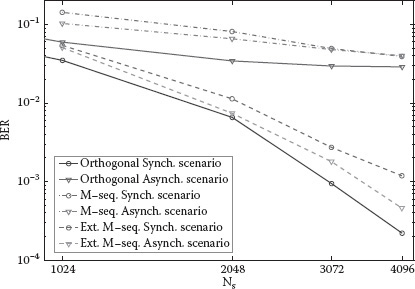
FIGURE 5.17 BER as a function of Ns and different spreading codes; 59 interfering tags. Useful tag at d = 7 m. Multipath 802.15.4a CM1 channel considered [57].
We investigate the theoretical performance of a localization system based on UWB backscatter signals. Consider a scenario composed of N readers placed at known coordinates (xi,yi), with i = 1, 2, … N, which interrogate a tag located in unknown coordinates p = (x,y) with the purpose to obtain an estimate of the reader-tag distance di (through the measurement of the round-trip time of the backscattered signal) and determine the tag’s position by means, for example, of a classical multilateration localization algorithm [33].
Range measurement ˆdi
fi (ˆdi|p) = 1√2πσ (di (p)) exp (− (ˆdi − di (p))22σ2 (di (p))). |
(5.31) |
Let ˆp = (ˆx, ˆy)
PEB (x,y) = √∑Ni=1 Ai(∑Ni=1 Aic2i) (∑Ni=1 Ais2i) − (∑Ni=1 Aicisi)2 |
(5.32) |
where Ai ≜ 1/σ2i, ci ≜ cos θi,
In Figure 5.18 an example of theoretical achievable localization accuracy evaluated using (5.5) and (5.32) in a square area of 20 × 20 m composed of four readers is given. Distance estimation between each reader and the tag is obtained by measuring the signal propagation round-trip time. Results are derived starting from measured data in AWGN and considering random tag orientation. The same system parameters used in Section 5.5.2.1 are considered with Ns = 1000. In particular, Figure 5.18 shows the covered locations in a predefined grid, where a location is defined to be covered if, for at least 70% of possible tag orientations, the localization estimation RMSE is less than 20 cm. As can be noted, even in a relatively big area, the number of locations covered with high-accuracy results can be quite large, thus making submeter accuracy localization using backscatter signaling feasible. More extended analysis starting from real measurements can be found in Heiries et al. [46] and Bartoletti and Conti [62].

FIGURE 5.18 Coverage map using four readers (R1-R4) and passive UWB tags. Locations with position estimation RMSE less than 20 cm are marked [5].
An interesting technology exploiting backscatter signaling is represented by full passive or chipless tags. In chipless tags neither the microcontroller nor backscatter modulator is present, so then no energy source is required. They are based on passive antenna loads whose response is tag dependent. Therefore, the reader can identify different tags by analyzing the structure of the signal backscattered.
An example of chipless tag can be found in Zheng et al. [63], where the proposed tag is composed of a transmission line with mismatched reconfigurable impedances encoding the tag ID as shown in Figure 5.19. Very low cost inkjet printing is used to reconfigure the tag ID by creating intersections between the preprinted planar capacitors and the transmission line. When a UWB interrogation signal is received, the impedances cause reflected waves that travel backward along the transmission line. The encoded ID can be gained by analyzing the reflected response at the reader side. This technology is quite promising thanks to the extremely low cost implementation, even though current implementations suffer from several drawbacks in terms of maximum ID length (up to 8 bits) and dimensions (a 40 cm long transmission line is required).

FIGURE 5.19 Example of UWB chipless tag proposed in Zheng et al. [63].
Similar approaches are represented by multiresonator chipless tags, where tag ID is encoded into the spectral domain in both magnitude and phase of the spectrum [64].
5.6.2 HIGH-ACCURACY RADIO DETECTION, IDENTIFICATION, AND LOCALIZATION APPLICATIONS
The possibility of designing a cheap wireless network composed of several radio transmitting/receiving nodes able to detect, localize, and track with high precision moving objects—also discriminating between collaborative objects (objects equipped with tags) and noncollaborative objects (i.e., nonidentifiable [targets])—is particularly attractive. UWB is the only technology today that allows in principle the integration of object detection (through the concept of wireless sensor radar [WSR]) [21,62,65], object identification (RFID), and localization features (RTLS) to form a new concept of integrated system we name high-accuracy radio detection, identification, and localization (Hi-RADIAL).
A wireless network integrating such capabilities would lead to a relevant improvement in development and reliability of a wide range of advanced applications including logistics (package tracking), security (localizing authorized persons in high-security areas as well as homeland), medical (monitoring of patients), family communications/supervision of children, search and rescue (communications with fire fighters or avalanche/earthquake victims), automotive safety, and military applications.
A possible application scenario example is reported in Figure 5.20, where an indoor area must be monitored and protected by a Hi-RADIAL network composed of several UWB radio transmitters/receivers placed in known positions. All authorized persons (or objects) are equipped with a UWB RFID tag. The system has the task to detect a noncollaborative moving target (intruder) entering the area and, at the same time, discriminate between authorized persons (by identifying their tags) and unauthorized persons. The position of all targets and tags is tracked in real time with submeter precision. Examples of specific applications falling in this scenario are represented by indoor/outdoor advanced security systems for personal safety, package tracking in supply chain management, advanced systems for the surveillance of factory warehouses, and automotive applications.

FIGURE 5.20 Example of advanced security application using the Hi-RADIAL concept.
The Hi-RADIAL concept opens new, challenging issues determined by spectrum use regulatory constraints; application requirements; wireless communication issues, such as the presence of dense multipath; clutter; NLOS conditions; interference; and the need of low cost and low consumption devices [19].
The author would like to thank Andrea Conti, Nicoló Decarli, Raffaele D’Errico, Francesco Guidi, and Alain Sibille. This work has been performed within the framework FP7 European Project SELECT (grant agreement no. 257544).
1. K. Finkenzeller, in RFID handbook: Fundamentals and applications in contactless smart cards and identification, 2nd ed. New York: Wiley, 2004.
2. E. Ngai, K. K. Moon, F. J. Riggins, and C. Y. Yi, RFID research: An academic literature review (1995–2005) and future research directions. International Journal of Production Economics, vol. 112, no. 2, pp. 510–520, 2008, Special Section on RFID: Technology, Applications, and Impact on Business Operations.
3. V. Chawla and D. S. Ha, An overview of passive RFID. IEEE Applications & Practice, pp. 11–17, Sept. 2007.
4. R. Das and P. Harrop, RFID forecast, players and opportunities 2007–2017 (available online at http://www.idtechex.com), 2007.
5. D. Dardari, R. D’Errico, C. Roblin, A. Sibille, and M. Z. Win, Ultrawide bandwidth RFID: The next generation? Proceedings of the IEEE, Special Issue on RFID—A Unique Radio Innovation for the 21st Century, vol. 98, no. 9, pp. 1570–1582, Sept. 2010.
6. R. Verdone, D. Dardari, G. Mazzini, and A. Conti, Wireless sensor and actuator networks: Technologies, analysis and design. London: Elsevier Ltd., 2008.
7. D. Ha and P. Schaumont, Replacing cryptography with ultra wideband (UWB) modulation in secure RFID. 2007 IEEE International Conference on RFID, Grapevine, TX, March 2007.
8. T. van Deursen and S. Radomirović, Security of RFID protocols—A case study. Electron Notes in Theoretical Computer Science, vol. 244, pp. 41–52, 2009.
9. J. Griffin and G. Durgin, Reduced fading for RFID tags with multiple antennas. 2007 IEEE Antennas and Propagation International Symposium, pp. 1201–1204, June 2007.
10. M. Z. Win and R. A. Scholtz, Impulse radio: How it works. IEEE Communications Letters, vol. 2, no. 2, pp. 36–38, Feb. 1998.
11. Proceedings of IEEE, Special Issue on UWB Technology & Emerging Applications, Feb. 2009.
12. R. J. Fontana and S. J. Gunderson, Ultra-wideband precision asset location system. Proceedings of IEEE Conference on Ultra Wideband Systems and Technologies (UWBST), vol. 21, no. 1, pp. 147–150, May 2002.
13. Time domain corporation, www.timedomain.com
14. Ubisense limited, www.ubisense.net
15. Zebra enterprise solutions, zes.zebra.com
16. IEEE 802.15.4f Draft, IEEE standard for information technology—Telecommunications and information exchange between systems—Local and metropolitan area networks—Specific requirements—Part 15.4: Wireless medium access control (MAC) and physical layer (PHY) specifications for low rate wireless personal area networks (WPANs)—Amendment: Active RFID system PHY. 2011. Online. Available: http://www.ieee802.org/15/pub/TG4f.html
17. D. Dardari, Method and apparatus for communication in ultra-wide bandwidth RFID systems. International Patent Application PCT/IB2009/000 360, Feb. 25, 2009.
18. D. Dardari and R. D’Errico, Passive ultrawide bandwidth RFID. IEEE Global Communications Conference (GLOBECOM 2008), New Orleans, LA, Nov. 2008.
19. SELECT (smart and efficient location, identification, and cooperation techniques), FP7 European Project, http://www.selectwireless.eu
20. Z. Sahinoglu, S. Gezici, and I. Guvenc, in Ultra-wideband positioning systems: Theoretical limits, ranging algorithms, and protocols. New York: Cambridge University Press, 2008.
21. E. Paolini, A. Giorgetti, M. Chiani, R. Minutolo, and M. Montanari, Localization capability of cooperative anti-intruder radar systems. EURASIP Journal on Advances in Signal Processing, Special Issue on Cooperative Localization in Wireless Ad Hoc and Sensor Networks, vol. 2008, Article ID 726854, p. 14, 2008.
22. Federal Communications Commission, Revision of part 15 of the commission’s rules regarding ultra-wideband transmission systems, first report and order (ET Docket 98-153), adopted Feb. 14, 2002, released April 22, 2002.
23. European Commission, Commission decision of 21 February 2007 on allowing the use of the radio spectrum for equipment using ultra-wideband technology in a harmonized manner in the community. Official Journal of the European Union, vol. C (2007) 522, Feb. 2007.
24. European Commission, Amendment to ECC decision to include DAA: Ecc/dec/(06)12 amended, October 2008.
25. European Commission, Draft ECC report 170 in ECC consultation ECC report on specific UWB applications in the bands 3.4–4.8 GHz and 6–8.5 GHz location tracking applications for emergency services (LAES), location tracking applications type 2 (LT2) and location tracking and sensor applications for automotive and transportation environments (LTA).
26. European Commission, Draft ECC recommendation (11)09 UWB location tracking systems type 2 (LT2). Recommendation adopted by the Working Group Frequency Management (WG FM), 2009.
27. WiMedia Alliance, Wimedia, 2005. Online. Available: http://www.wimedia.org
28. IEEE standard for information technology—Telecommunications and information exchange between systems—Local and metropolitan area networks—Specific requirement part 15.4: Wireless medium access control (MAC) and physical layer (PHY) specifications for low-rate wireless personal area networks (WPANs), IEEE Std 802.15.4a-2007 (amendment to IEEE Std 802.15.4-2006), pp. 1–203, 2007.
29. M. Baghaei-Nejad, Z. Zou, H. Tenhunen, and L.-R. Zheng, A novel passive tag with asymmetric wireless link for RFID and WSN applications. ISCAS 2007. IEEE International Symposium on Circuits and Systems, 2007, pp. 1593–1596, May 2007.
30. D. Cassioli, M. Z. Win, and A. F. Molisch, The ultra-wide bandwidth indoor channel: From statistical model to simulations. IEEE Journal of Select Areas in Communication, vol. 20, no. 6, pp. 1247–1257, Aug. 2002.
31. A. F. Molisch, D. Cassioli, C.-C. Chong, S. Emami, A. Fort, B. Kannan, J. Karedal, et al., A comprehensive standardized model for ultrawideband propagation channels. IEEE Transactions Antennas Propagation, vol. 54, no. 11, pp. 3151–3166, Nov. 2006, Special Issue on Wireless Communications.
32. M. Z. Win and R. A. Scholtz, Characterization of ultra-wide bandwidth wireless indoor communications channel: A communication theoretic view. IEEE Journal of Select Areas Communication, vol. 20, no. 9, pp. 1613–1627, Dec. 2002.
33. D. Dardari, E. Falletti, and M. Luise, in Satellite and terrestrial radio positioning techniques—A signal processing perspective. Elsevier Ltd, London, 2011.
34. D. Dardari, A. Conti, U. Ferner, A. Giorgetti, and M. Z. Win, Ranging with ultrawide bandwidth signals in multipath environments. Proceedings of IEEE, Special Issue on UWB Technology & Emerging Applications, vol. 97, no. 2, pp. 404–426, Feb. 2009.
35. C.-C. Chong and S. K. Yong, A generic statistical-based UWB channel model for high-rise apartments. IEEE Transactions Antennas Propagation, vol. 53, pp. 2389–2399, 2005.
36. A. Molisch, K. Balakrishnan, D. Cassioli, C.-C. Chong, S. Emami, A. Fort, J. Karedal, et al., IEEE 802.15.4a channel model—Final report, 2005.
37. A. Saleh and R. A. Valenzuela, A statistical model for indoor multipath propagation. IEEE Journal of Select Areas Communication, vol. 5, no. 2, pp. 128–137, Feb. 1987.
38. R. C. Hansen, Relationship between antennas as scatters and as radiators. Proceedings of the IEEE, vol. 77, no. 5, 1989.
39. K. Penttila, M. Keskilammi, L. Sydanheimo, and M. Kivikoski, Radar cross-section analysis for passive RFID systems. IEE Proceedings on Microwave and Antennas Propagation, vol. 153, no. 1, pp. 103–109, Feb. 2006.
40. S. Hu, C. L. Law, Z. Shen, L. Zhu, W. Zhang, and W. Dou, Backscattering cross section of ultrawideband antennas. IEEE Antennas Wireless Propagation Letters, vol. 6, pp. 70–72, 2007.
41. S. Hu, Y. Zhou, C. L. Law, and W. Dou, Study of a uniplanar monopole antenna for passive chipless UWB-RFID localization system. IEEE Transactions Antennas Propagation, vol. 58, no. 2, pp. 271–278, 2010.
42. A. Sibille, M. Sacko, Z. Mhanna, F. Guidi, and C. Roblin, Joint antenna-channel statistical modeling of UWB backscattering RFID. Proceedings of the 2011 IEEE International Conference on Ultra-Wideband (ICUWB 2011), Sept. 2011, pp. 474–478.
43. F. Guidi, A. Sibille, D. Dardari, and C. Roblin, UWB RFID backscattered energy in the presence of nearby metallic reflectors. European Conference on Antennas and Propagation 2011, Rome, Italy, April 2011.
44. D. Dardari, F. Guidi, C. Roblin, and A. Sibille. Ultra-wide bandwidth backscatter modulation: Processing schemes and performance. EURASIP Journal on Wireless Communications and Networking, vol. 2011, no. 1, 2011.
45. C. Roblin, S. Bories, and A. Sibille, Characterization tools of antennas in the time domain. Proceedings of International Workshop on Ultra Wideband Band Systems (IWUWBS 2003).
46. V. Heiries, K. Belmkaddem, F. Dehmas, B. Denis, L. Ouvry, and R. D’Errico, UWB backscattering system for passive RFID tag ranging and tracking. Proceedings of the 2011 IEEE International Conference on Ultra-Wideband (ICUWB 2011), pp. 489–493, Sept. 2011.
47. F. Guidi, D. Dardari, C. Roblin, and A. Sibille, Backscatter communication using ultrawide bandwidth signals for RFID applications, in D. Giusto et al. (eds.), The Internet of things: 20th Tyrrhenian Workshop on Digital Communications, SpringerScience+BusinessMedia, Pula, Sardinia, Italy, pp. 251–262, Sept. 2009.
48. D. Dardari, Pseudo-random active UWB reflectors for accurate ranging. IEEE Communications Letters, vol. 8, no. 10, pp. 608–610, Oct. 2004.
49. L. Stoica, A. Rabbachin, H. O. Repo, T. S. Tiuraniemi, and I. Oppermann, An ultrawide-band system architecture for tag based wireless sensor networks, IEEE Transactions Vehicular Technolology, vol. 54, no. 5, pp. 1632–1645, Sept. 2005.
50. Z. Zou, M. Baghaei-Nejad, H. Tenhunen, and L.-R. Zheng, An efficient passive RFID system for ubiquitous identification and sensing using impulse UWB radio, e & i Elektrotechnik und Informationstechnik, Springer Wien, vol. 124, no. 11, pp. 397–403, Nov. 2007.
51. J. A. Paradiso and T. Starner, Energy scavenging for mobile and wireless electronics, IEEE Pervasive Computing, pp. 18–26, Jan.–March 2005.
52. K. Pahlaven and H. Eskafi, Radio frequency tag and reader with asymmetric communication bandwidth, US Patent 7,180,421 B2, Feb. 20, 2007.
53. A. Muchkaev, Carrierless RFID system, US Patent 7,385,511 B2, June 10, 2008.
54. J. Jantunen, A. Lappetelainen, J. Arponen, A. Parssinen, M. Pelissier, B. Gomez, and J. Keignart, A new symmetric transceiver architecture for pulsed short-range communication. IEEE Global Communications Conference (GLOBECOM 2008), New Orleans, LA, Nov. 2008.
55. R. Vauche, E. Bergeret, J. Gaubert, S. Bourdel, O. Fourquin, and N. Dehaese, A remotely UHF powered UWB transmitter for high precision localization of RFID tag. Proceedings of the 2011 IEEE International Conference on Ultra-Wideband (ICUWB 2011), pp. 494–498, Sept. 2011.
56. J. Reunamaki, Ultra wideband radio frequency identification techniques, US Patent 7,154,396, Dec. 26, 2006.
57. F. Guidi, N. Decarli, D. Dardari, C. Roblin, and A. Sibille. Performance of UWB backscatter modulation in multi-tag RFID scenario using experimental data. IEEE International Conference on Ultra-Wideband, ICUWB 2011, Bologna, Italy, pp. 1–5, Sept. 2011.
58. W. Suwansantisuk and M. Z. Win, Multipath aided rapid acquisition: Optimal search strategies. IEEE Transactions Information Theory, vol. 52, no. 1, pp. 174–193, Jan. 2007.
59. C. Xu and C. L. Law, TOA estimator for UWB backscattering RFID system with clutter suppression capability. EURASIP Journal on Wireless Communications and Networking, vol. 2010, Article ID 753129, 14 pp., 2010.
60. G. D. Vita and G. Iannaccone, Design criteria for the RF section of UHF and microwave passive RFID transponders. IEEE Transactions on Microwave Theory and Techniques, vol. 59, no. 9, pp. 2978–2990, Sept. 2005.
61. D. B. Jourdan, D. Dardari, and M. Z. Win, Position error bound for UWB localization in dense cluttered environments. IEEE Transactions Aerospace Electronic Systems, vol. 44, no. 2, pp. 613–628, April 2008.
62. S. Bartoletti and A. Conti, Passive network localization via UWB wireless sensor radars: The impact of TOA estimation. Proceedings of the 2011 IEEE International Conference on Ultra-Wideband (ICUWB 2011), pp. 258–262, Sept. 2011.
63. L. Zheng, S. Rodriguez, L. Zhang, B. Shao, and L.-R. Zheng, Design and implementation of a fully reconfigurable chipless RFID tag using inkjet printing technology. IEEE International Symposium on Circuits and Systems 2008 (ISCAS 2008), pp. 1524–1527, May 2008.
64. S. Preradovic, I. Balbin, N. Karmakar, and G. Swiegers, Multiresonator-based chipless RFID system for low-cost item tracking. IEEE Transactions on Microwave Theory and Techniques, vol. 57, no. 5, pp. 1411–1419, May 2009.
65. V. Casadei, N. Nanna, and D. Dardari, Experimental study in breath detection and human target ranging in the presence of obstacles using ultra-wideband signals. International Journal of Ultra Wideband Communications and Systems, Special Issue on Applications of Ultra Wideband Technology in Healthcare, 2011.
66. N. Decarli, F. Guidi, A. Conti, D. Dardari, Interference and clock drift in UWB RFID systems using backscatter modulation. IEEE International Conference on Ultra-Wideband, ICUWB 2012, Syracuse, NY September 2012, pp. 1–5.
* Two different values of tp are recommended [28]: tp = 1 ns and tp = 3.2 ns with ν = 0.6, corresponding to two different bandwidths, W = 1.6 GHz and W = 500 MHz, respectively.
* In general, p(t) can be a part of a multiple access signaling such as DS or TH as explained in Section 5.2.2. For band-limited signals, we consider Tp as the interval duration containing most of the signal energy.
† The CRB gives the theoretical limit on the mean square error (MSE) of any unbiased estimator and hence it represents a useful benchmark to assess the performance of any practical estimator.
* Parameter Beff is often called effective bandwidth.
* The structural mode scattered component is here conventionally defined as the signal scattered when the antenna load is matched. In the literature it is often defined with respect to the short circuit load [38]. In any case, whatever convention is adopted, the following analysis and the results are not affected.
* Multiple readers can access the same tag by using different reader codes, provided that they are designed with good cross-correlation properties.