
5
Solderless Breadboarding with the M5Stack
In the previous chapter, you learned about the various Snap Circuits blocks that extend the M5Stack Core operational functions. You learned about blocks that allow motion, lights, and sound to enhance the appeal to the user of an M5Stack Core. You learned how to program the LED MC using a basic procedure. The PICAXE microcontroller used in the LED MC was presented to you using an electronic circuit schematic diagram. Furthermore, you learned about the ALARM IC module and the ASIC used to produce various sound effects. With the alarm IC, you learned how to wire the Snap Circuits unit to produce sounds such as a machine gun, a siren, a fire engine, and a European siren. You learned about the snap pins for the LED MC and the alarm IC modules in the previous chapter. Lastly, an interface circuit technique for wiring the M5Stack Core to a Snap Circuits LED MC and alarm IC using a transistor relay driver circuit was presented in the previous chapter.
In this chapter, you will explore the transistor relay driver and additional interface circuits. With the knowledge of how to create a block diagram and electronic circuit schematic diagram obtained in Chapter 3, you will be able to wire the M5Stack Core to operate various electronic circuit devices. You will be introduced to littleBits electronic modules by wiring them to the M5Stack Core. Furthermore, you will learn how to wire a littleBits temperature sensor to the M5Stack Core and create a simulator monitor. A discrete LED electronic flasher and a transistor DC motor driver circuit controlled by an M5Stack Core will be presented in this chapter.
By the end of this chapter, you will know how to perform the following technical tasks with the M5Stack and solderless breadboarding:
- Build a Tinkercad Circuits transistor LED driver circuit model
- Wire and test an M5Stack Core discrete LED electronic flasher
- Wire and test an M5Stack Core discrete transistor motor driver circuit
- Wire and test an M5Stack Core littleBits temperature sensor simulator device
- Wire and test an M5Stack Core controller littleBits LED flasher
In this chapter, we are going to cover the following main topics:
- An introduction to electronic interfacing circuits
- Building a discrete transistor LED electronic flasher
- Building a discrete transistor DC motor driver circuit
- Building a littleBits temperature sensor M5Stack Core simulator monitor
- Building an M5Stack Core controller littleBits LED flasher
Technical requirements
To engage with the chapter’s learning content, you will need the M5GO IoT starter kit to explore the internal/external hardware electronics and software coding of your first basic application. littleBits, electronic modules, discrete resistors, transistors, an LED, an electromechanical relay, and jumper wires will be required to complete the projects in the chapter. Furthermore, the UiFlow code block software will be required to build and run the M5Stack Core mini programmable controller applications.
You will require the following:
- A littleBits w9 proto module
- A littleBits i12 temperature sensor
- A littleBits o1 LED
- A littleBits o2 long LED
- A littleBits o25 DC motor or equivalent
- A USB-C cable
- A 2N3904 NPN transistor
- A 1N4001 silicon diode
- An electromechanical relay module
- An electromechanical relay 3-5 V DC
- Two 560-ohm, +/5% (green, blue, brown, gold) resistors
- A 10-Kiloohm, +/5% (brown, black, orange, gold) resistor
- A discrete LED
Here is the GitHub repository for the software resources:
https://github.com/PacktPublishing/M5Stack-Electronic-Blueprints/tree/main/Chapter05
An introduction to electronic interfacing circuits
Wiring two non-compatible circuits requires an electrical connection method. The electrical connection method addresses control signal differences between the two non-compatible circuits. Electronic interfacing is an electrical wiring method that connects or links one circuit to another electrical device. Traditionally, there are two approaches to interfacing electronic circuits: input and output. Input interfacing is an electrical approach to adapting an electronic circuit’s output to the input of another circuit device. Output interfacing allows an electronic or electrical circuit to control a real-world device. A real-world device such as an electromechanical relay, a discrete LED, or a liquid-crystal display (LCD) is wired to the output of a controller or switching circuit. The input and output electronic interfacing circuits traditionally use basic components, such as resistors, capacitors, or transistors. The arrangement of these basic components will allow either an amplification, filtration, or voltage-level translation to occur. Figure 5.1 illustrates the concepts of basic input electronic interfacing circuits.
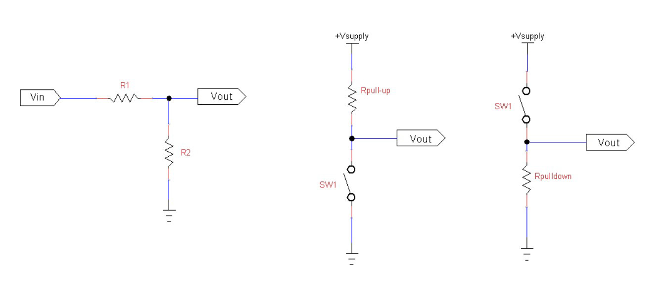
Figure 5.1 – Basic input electronic interfacing circuits
The idea behind these three basic input electronic interfacing circuits is to provide an output voltage (Vout) capable of allowing a compatible control signal to properly operate an input port or pin of a microcontroller or digital circuit. The basic input electronic interfacing circuits operate in the digital domain, thus providing a 0 or +Vsupply voltage to the input port or pin of a microcontroller or digital circuit. The voltage value of +Vsupply can be 3.3 V or 5 V, which is compliant with the input port or pin of the microcontroller or digital circuit. The two output electronic interfacing circuits are shown in Figure 5.2.

Figure 5.2 – Basic output electronic interfacing circuits
The transistors shown in Figure 5.2 provide sufficient amplification gain, thus capable of sinking and sourcing the current flow needed to properly work with the output port or pin of the microcontroller or digital logic gate. Sinking the current flow allows the transistor to provide a switched ground to the wired electrical or electromechanical load. Sourcing the current provides an active high-side voltage rail to the wired electrical or electromechanical load. Traditionally, the output electronic interfacing circuit will operate an electromechanical load such as an electric motor or relay. Operating a discrete LED or seven-segment LED display requires a transistor or an array of transistors to turn the individual segments of the optoelectronic component on or off.
Besides using discrete switching components such as a transistor, an IC may be used for an electronic interfacing circuit. A buffer is an electronic circuit used to isolate the input from the output. The input and output are decided by default in relation to the electronic circuits wired together. The buffer’s input impedance is high, therefore drawing little current flow to avoid disturbing the input of the target circuit. Impedance is the internal AC resistance of a circuit. Figure 5.3 illustrates a typical buffer IC.
Quiz 1
Electronic interfacing allows two approaches: jumper wires and terminal blocks. True or false?
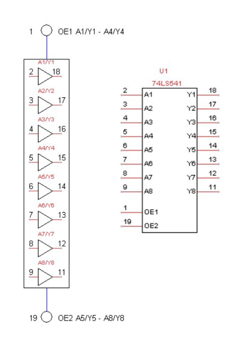
Figure 5.3 – A 74LS541 octal three-state buffer IC
You now have general knowledge about electronic interfacing and various approaches to wiring dissimilar circuits together. With this technical knowledge, you will be able to interface discrete circuits and littleBits electronic modules to the M5Stack Core. You will apply this technical knowledge in the next section by building a discrete transistor LED electronic flasher operated by an M5Stack Core.
Building a discrete transistor LED electronic flasher
You learned about electronic interfacing circuits in the previous section. In this section, you will apply this technical knowledge by building a discrete transistor LED electronic flasher operated by an M5Stack Core. To obtain the baseline information about the M5Stack Core-operated device, you will build a virtual transistor LED driver circuit. You will create the virtual transistor LED driver circuit using Tinkercad Circuits. Tinkercad Circuits is an online electronic circuit simulator platform that allows various discrete electrical electronic, digital, and microcontroller circuits to be constructed and tested. This online electronics laboratory was developed by Autodesk. You will use the electronic circuit schematic provided in Figure 5.4 to build the Tinkercad Circuits transistor LED driver circuit.

Figure 5.4 – The transistor LED driver circuit
Tinkercad Circuits is a popular online electronics simulator that allows you to test microcontrollers and digital and analog circuits. With Tinkercad Circuits, you can easily test the electrical behavior or operation of the transistor LED driver circuit shown in Figure 5.4. You can assess the Tinkercad Circuits online electronics simulator environment at this URL:
https://www.tinkercad.com/learn/circuits
After signing up and logging in to the free simulator website, you will see the Tinkercad Circuits virtual lab bench and user interface (UI) as shown in Figure 5.5.
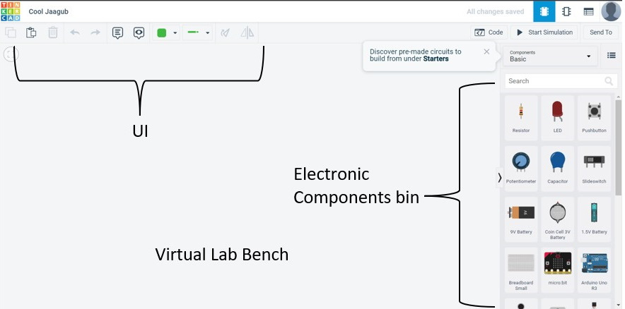
Figure 5.5 – The Tinkercad Circuits electronic simulator environment
You will create the circuit using a solderless breadboard and the electronic circuit components as shown in Figure 5.4. You can wire the transistor LED driver circuit using the virtual model as shown in Figure 5.6. You will adjust the DC power supply for a +5 V DC voltage value. Pressing the tactile pushbutton switch will allow the NPN bipolar junction transistor (BJT) to sink current or provide ground through the collector-emitter leads. The current flowing through the NPN BJT collector-emitter leads will turn on the LED.
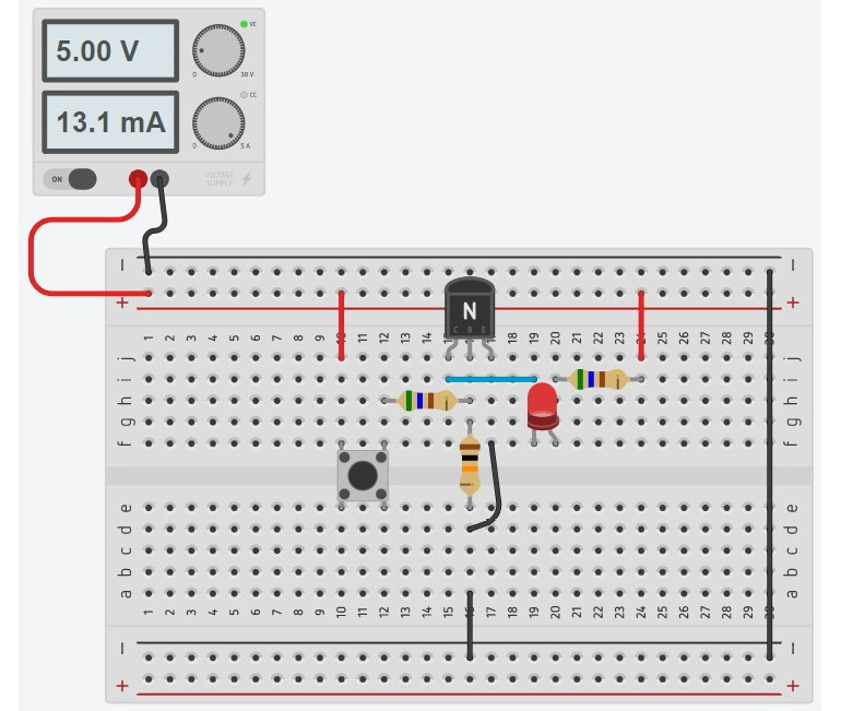
Figure 5.6 – A solderless breadboard transistor LED driver circuit
Figure 5.7 provides additional component value information to assist you in the electrical wiring of the transistor LED driver circuit. The reference designators are included to align the electronic circuit schematic diagram shown in Figure 5.4 with the components shown on the solderless breadboard.

Figure 5.7 – Transistor LED driver circuit reference designators
You can add digital ammeters and a voltmeter to obtain additional electrical information regarding the driver circuit’s operation. Figure 5.8 shows the current branches of the transistor driver’s base emitter and collector emitter. You will notice the voltmeter reading of 739 mV at the base of the transistor. The value displayed on the digital voltmeter is the base-emitter junction voltage (VBE). Typically, for silicon transistors, the VBE junction voltage is around 600 to 700 mV.
Note
To learn more about Tinkercad Circuits, refer to the online official guide at the following URL: https://www.tinkercad.com/blog/official-guide-to-tinkercad-circuits.
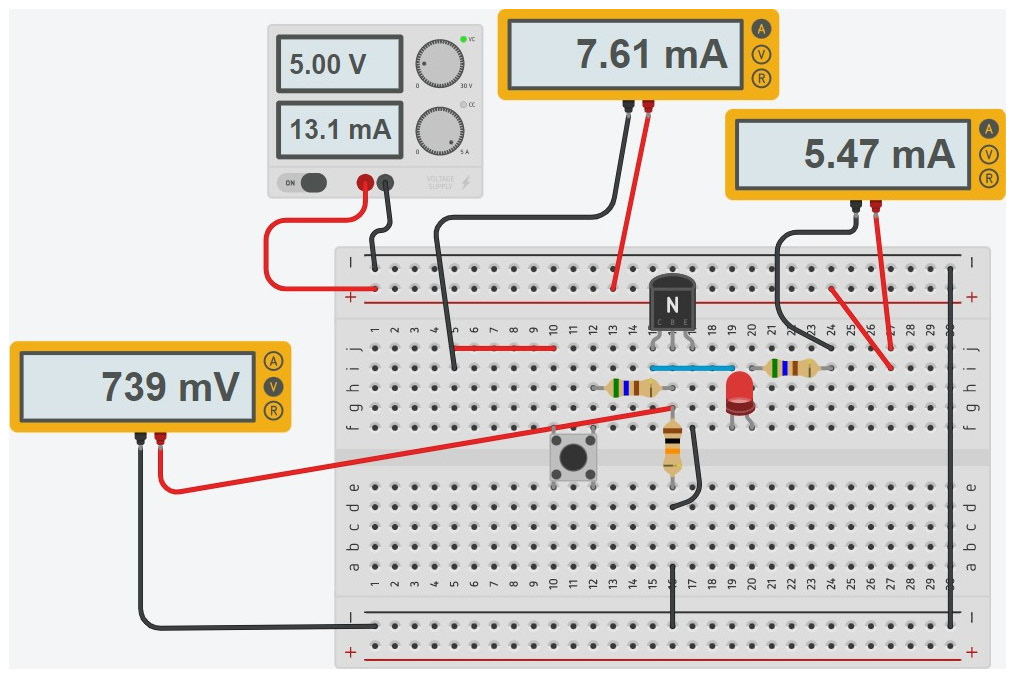
Figure 5.8 – Transistor LED driver circuit branch currents and VBE
Quiz 2
Reviewing the DC power supply’s ammeter reading shown in Figure 5.8, are the two branch currents correct?
Congratulations – you have successfully built and tested a discrete transistor LED driver circuit using the online Tinkercad Circuits simulator platform. You now understand the transistor LED driver’s circuit operation and wiring configuration. With this knowledge, you will build a physical circuit using real electronic components and the M5Stack Core. The M5Stack Core interfacing concept is shown in Figure 5.9.
Note
The transistor shown in Figure 5.8 has a pin orientation of Collector (C), Base (B), and Emitter (E). The 2N3904 NPN transistor has a pin orientation of EBC.
With the use of the circuit schematic and electrical wiring diagrams, you can wire up a physical transistor LED driver circuit prototype. The physical transistor LED driver circuit prototype can be wired to an M5Stack Core. You can program the M5Stack Core to operate the transistor LED driver circuit. Therefore, you can program the M5Stack Core to turn the transistor LED driver circuit on and off.

Figure 5.9 – M5Stack Core interfacing concept
With the M5Stack Core interfacing concept illustrated in Figure 5.9, along with the electrical wiring diagram shown in Figure 5.10, you can wire a transistor LED electronic flasher. The unique feature of this transistor LED electronic flasher is the ability to change the flashing rate of the optoelectronic-based circuit using this interfacing concept. The transistor LED electronic flasher wiring diagram is shown next.
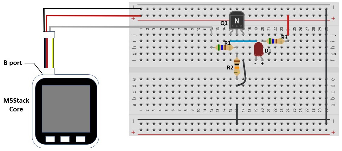
Figure 5.10 – Electrical wiring diagram for the transistor LED electronic flasher
You can also use the electronic circuit schematic diagram shown in Figure 5.11 to wire the M5Stack Core-based transistor LED flasher device.

Figure 5.11 – Electronic circuit schematic diagram for the transistor LED electronic flasher
The author’s completed wired transistor LED electronic flasher circuit prototype is shown next.
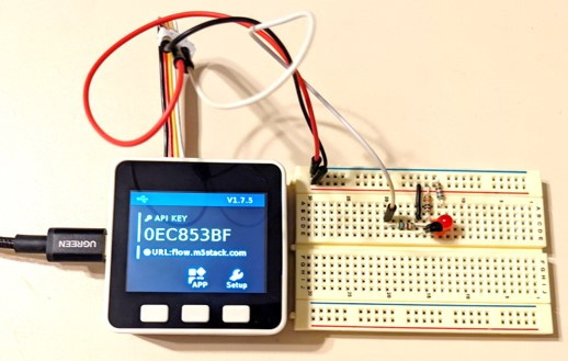
Figure 5.12 – Transistor LED electronic flasher circuit prototype
To operate the transistor LED electronic flasher, you will use the UiFlow Blockly code shown in Figure 5.13.
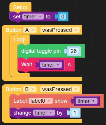
Figure 5.13 – UiFlow Blockly code for the programmable transistor LED flasher
Here, you can see the label0 Blockly code in the Label code block assigned to the timer variable. You will provide a UI for the M5Stack Core to display a timer value when the B button is pressed. Figure 5.14 shows the UI layout for displaying the timer value on the M5Stack Core LCD.

Figure 5.14 – Timer value UI layout
Interactive quiz 1
By modifying the change timer code instruction shown in Figure 5.13 to by 2, what number will be displayed on the M5Stack Core LCD when running the code?
Upon running the code on the M5Stack Core, pressing the B button allows you to set the timer value. The timer value provides the on-and-off delays that allow the LED to blink. You will press the A button to allow the LED to blink at the set time delay value programmed using the B button. Figure 5.15 illustrates setting the timer value by using the B button. To enter a new time delay value, double-press the M5Stack Core reset button and run the code on the ESP32-based device.
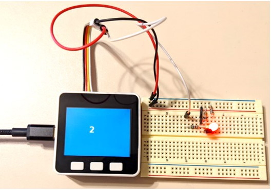
Figure 5.15 – The transistor LED flasher is programmed with a 2-second toggle delay
Congratulations – you have successfully wired and tested a transistor LED flasher that is enabled by the M5Stack Core. You used a transistor as an electronic switch to interface the M5Stack Core with a discrete LED. In the next section, you operate a small DC motor using the M5Stack Core.
Building a discrete transistor DC motor driver circuit
You have built and tested a transistor LED flasher using discrete electronic components. You have used the M5Stack Core as a programmable controller, thus setting various LED flash rates. You will use the operational concepts implemented previously with the transistor LED driver project to build an M5Stack Core-operated DC motor controller. Figure 5.16 shows the concept of the M5Stack Core interfacing circuit.
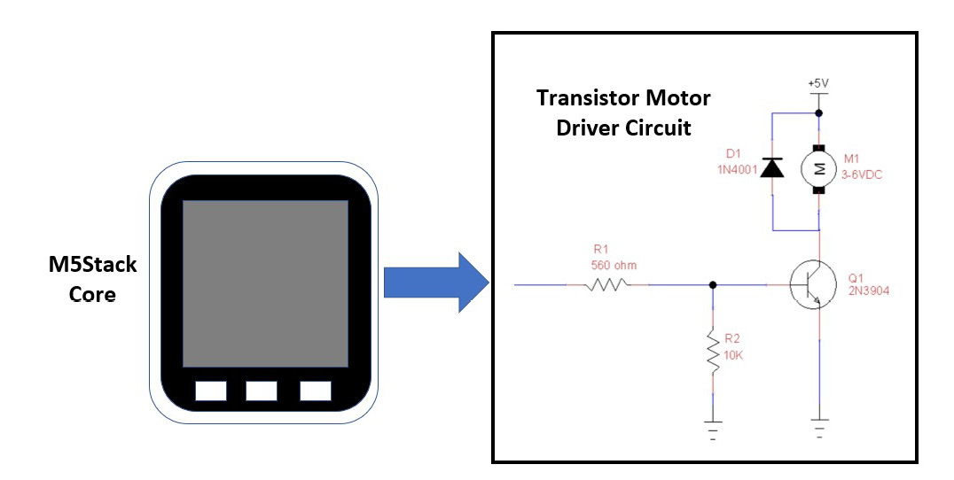
Figure 5.16 – The concept of the M5Stack Core interfacing circuit
With the M5Stack Core interface illustrated in Figure 5.16, along with the electrical wiring diagram shown in Figure 5.17, you can wire a transistor DC motor driver circuit to an M5Stack Core. The unique feature of this transistor DC motor driver is its ability to operate an electric motor using this interface. The transistor DC motor driver wiring diagram is shown next.
Interactive quiz 2
Redraw the transistor motor driver circuit using a PNP transistor.
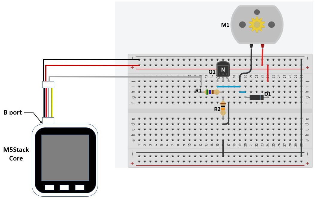
Figure 5.17 – Electrical wiring diagram of a transistor DC motor driver
You can also use the electronic circuit schematic diagram shown in Figure 5.18 to wire the M5Stack Core-based transistor DC motor device.
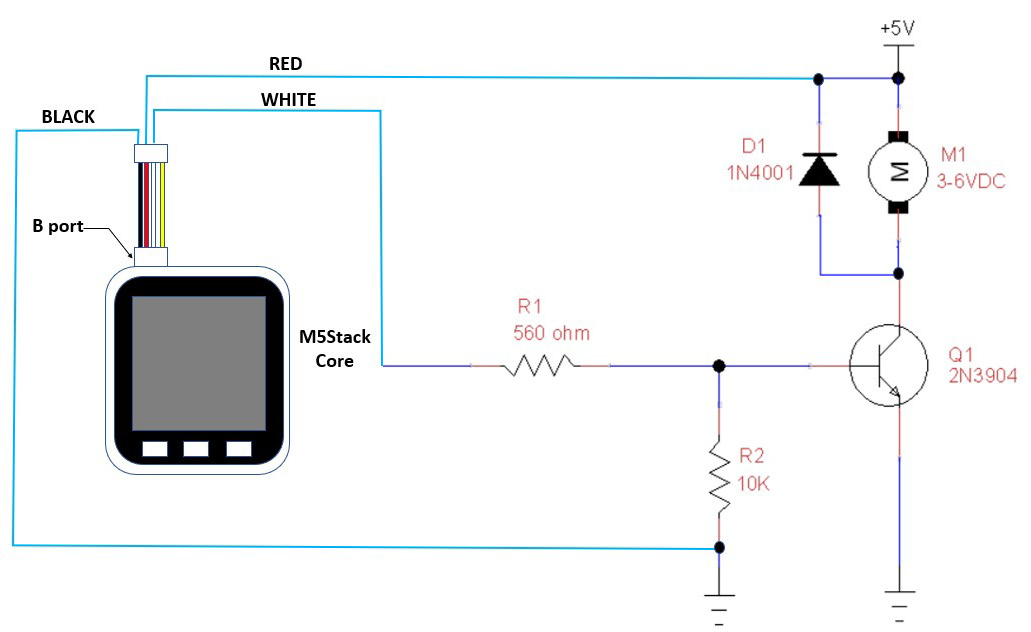
Figure 5.18 – Electronic circuit schematic diagram for a transistor DC motor driver
The author’s completed wired transistor DC motor driver circuit prototype is shown next.

Figure 5.19 – Transistor DC motor driver circuit prototype
To test the transistor DC motor driver, you will use the UiFlow Blockly code shown in Figure 5.20.

Figure 5.20 – UiFlow Blockly code for the M5Stack Core-enabled transistor DC motor driver
You will use a UI that is aesthetically appealing and informative for the user of the transistor DC motor driver circuit. The aesthetics consist of the controller’s name displayed at the top, along with a READY prompt. Pressing the A button will start the transistor driver operating the DC motor. Pressing the B button will stop the DC motor. After a 1-second delay, the READY prompt is displayed. The UI that aligns with the Blockly code shown in Figure 5.21 is shown next. The Blockly code will create a basic on/off control for the transistor DC motor driver.
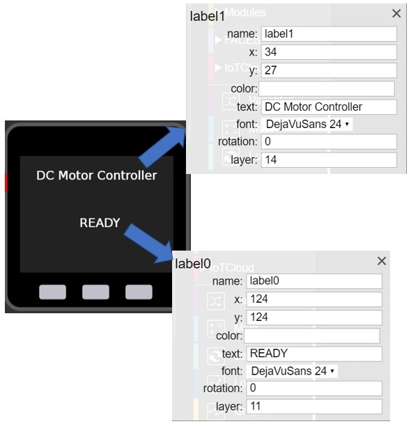
Figure 5.21 – The transistor DC motor driver UI
You can improve the UI layout shown in Figure 5.21 by adding ON and OFF labels above the respective buttons. With this information included, there will be no confusion as to how to start and stop the DC motor. You have now developed a human input module (HIM) that provides direct control of the transistor DC motor driver circuit with text to operate the device. An HIM is an electronic module that allows you to configure the operation of the electric motor drive system. Figure 5.22 shows the revised HIM-based UI.
Interactive quiz 3
If an LED with a limiting resistor is wired across R2, will the device turn on when the M5Stack Core’s A button is pressed?
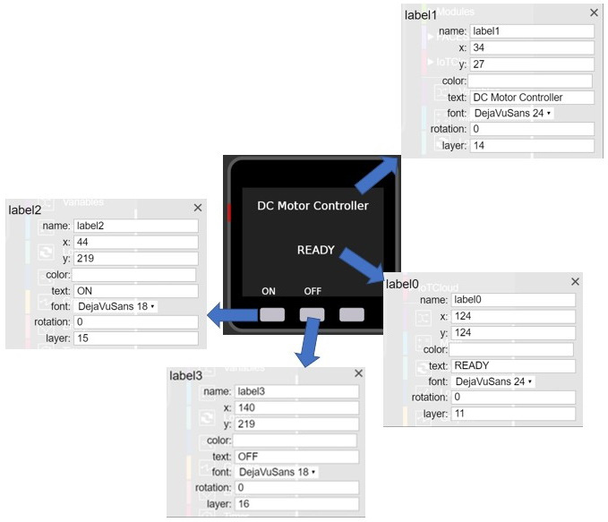
Figure 5.22 – An improved UI
Upon running the Blockly code shown in Figure 5.20, the improved UI will appear on the M5Stack Core’s thin film transistor (TFT) LCD. Figure 5.23 illustrates the actual improved M5Stack Core’s UI. You now have an HIM-based UI to operate the transistor motor driver circuit easily without confusion.
Quiz 3
Which label attribute allows you to make the text red?
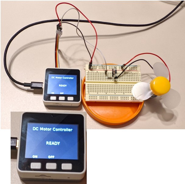
Figure 5.23 – The M5Stack Core’s improved UI
Congratulations – you have completed the building and testing of a discrete transistor motor driver circuit. You have explored various on/off and timing controls to operate a discrete transistor motor driver circuit with an M5Stack Core. Moreover, you enhanced the UI by adding additional labels to make operating a wired DC motor with the M5Stack Core using a transistor driver circuit easier. In the next section, you will gain knowledge of surface-mount circuits using a littleBits electronic module. You will learn how to interface the littleBits electronic module to the M5Stack Core using a proto module to build a temperature sensor simulator module.
Interactive quiz 4
On the UI shown in Figure 5.23, can the ON and OFF text be changed to START and STOP?
Building a littleBits temperature sensor M5Stack Core simulator monitor
In this section, you will take your knowledge of the littleBits proto module and build a physical simulator with a monitor. The technical concept behind this simulator monitor project is to create a physical model of a temperature sensor using a littleBits slide dimmer control. By adjusting the slide dimmer control, a simulated temperature reading will be displayed on the M5Stack Core’s TFT LCD. Upon the slide dimmer control reading exceeding a preset value, the M5Stack Core will turn on the internal LED bar. Figure 5.24 shows the temperature sensor simulator monitor concept block diagram.
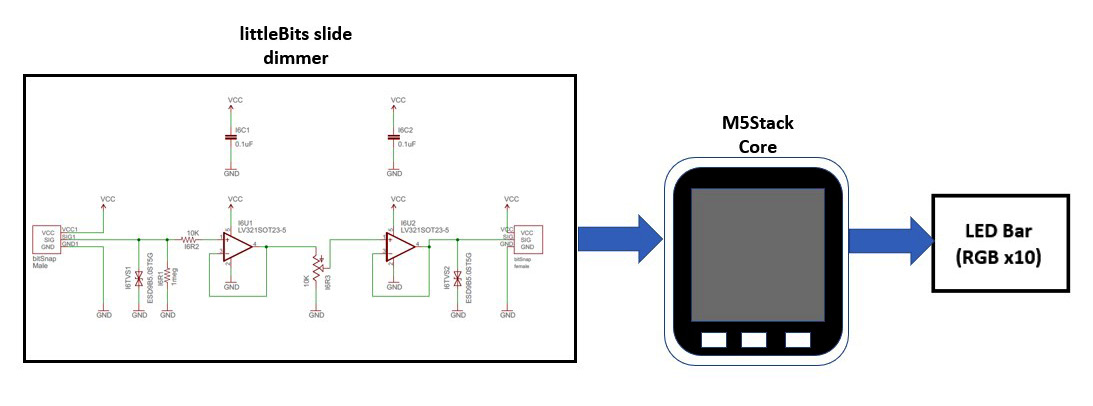
Figure 5.24 – Block diagram for the M5Stack Core temperature sensor simulator monitor
You will use the angle unit Blockly code block to capture the analog voltage values generated by the slide dimmer module. The angle unit Blockly code block will be aided by the label code block. The label code block will display the slide dimmer control value on the M5Stack Core’s TFT LCD. The angle unit Blockly code block is displayed in Figure 5.25.

Figure 5.25 – The angle unit Blockly code block
You will need to add this unit to the palette of Blockly code blocks. With your mouse, click on the + plus sign to display the available M5Stack Core units. You will select the angle unit with your mouse. Once you have made the selection with a mouse click, the angle unit will be displayed on the UiFlow layout section of the UiFlow coding environment. Figure 5.26 illustrates the placement of the angle unit in the UiFlow coding environment.

Figure 5.26 – Added angle unit to UiFlow layout area
You will use a slide dimmer control instead of the M5Stack Core’s angle unit to simulate the operation of a temperature. A traditional temperature sensor reacts to various levels of hot and cold stimuli by changing its internal resistance. If the surrounding temperature is cold, the resistance will be high. Conversely, if the temperature level is high, the resistance will be low. The inverse behavior of the sensor reactions to temperature levels is known as negative compensation. To be more accurate, the inverse temperature-resistance sensor reaction is known as the negative temperature coefficient (NTC). A thermistor is a small resistive electrical component whose behavior to temperature versus resistance is based on the NTC operation. Figure 5.27 illustrates an NTC thermistor and its temperature-to-resistance curve.

Figure 5.27 – A typical NTC thermistor’s temperature-to-resistance curve
You will notice that as temperature increases, the thermistor’s resistance decreases. With a decrease in temperature, the NTC thermistor’s resistance increases. The simulator works in the same manner as an NTC thermistor. With the slide dimmer in the far-right position, the M5Stack Core’s TFT LCD will display 0°C. As you move the slide dimmer to the left, the M5Stack Core’s TFT LCD will show an increase in temperature. You now understand the temperature sensor simulator operation. You will begin the process of building the temperature sensor simulator shortly.
The first step in building the temperature sensor simulator is to wire an M5Stack Core jumper harness to a littleBits proto module. You will use Figure 5.28 to wire the jumper harness to the proto module. The actual assembly build of the jumper harness to the proto module is shown in Figure 5.29. The M5Stack Core will power the slide dimmer control’s electronic interface circuit. The red and black wires provide +5 V and ground to operate the two operational amplifiers soldered to the bottom side of the slide dimmer control.

Figure 5.28 – Attaching the jumper harness to the proto module

Figure 5.29 – Complete jumper wire harness assembly
The two operational amplifiers provide the appropriate sourcing output current and voltage required for the M5Stack Core to read the adjusted signal values produced by the slide dimmer control’s potentiometer. Figure 5.30 shows the electronic interface circuit of the slider dimmer control. The bit snaps on each end of the slide dimmer control provide the +5 V, GND, and signal required for the electrical interface with the M5Stack Core’s B port.

Figure 5.30 – Electronic interface circuits for the slider dimmer control
The electrical-electronics circuit schematic diagram for the M5Stack Core and the slider dimmer control is shown in Figure 5.31.
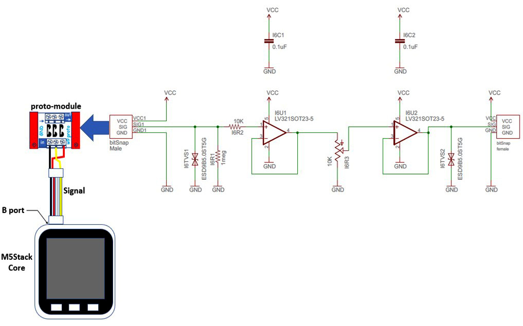
Figure 5.31 – Electronic circuit schematic diagram for the M5Stack Core and slide dimmer control
With the jumper harness wired to the proto module, you can attach the slide dimmer control to the assembled electrical interface unit. Figure 5.32 shows the slide dimmer attached to the proto module. Figure 5.32 clarifies the electronic circuit schematic diagram provided in Figure 5.31 in terms of the two littleBits components’ magnetic attachment.

Figure 5.32 – Slide dimmer control for the proto module
This assembled electrical interface unit to the M5Stack Core completes the prototype build of the temperature sensor simulator device. Figure 5.33 shows the complete temperature sensor simulator with a monitor. Congratulations – you have completed the assembly of your temperature sensor simulator with a monitor. The final step in this project is to program the device to display temperature values and provide a visual alarm upon exceeding a specified detection level.
Note
To provide electrical integrity and mechanical stability while adjusting the slide dimmer control, mount the operational amplifier-based potentiometer and the proto board on a littleBits mounting plate.
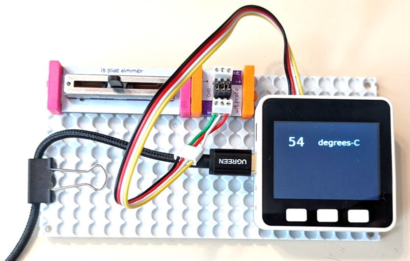
Figure 5.33 – The complete prototype temperature sensor simulator with a monitor
To create an aesthetically pleasing M5Stack Core UI, you will place the labels as shown in Figure 5.34 onto the UiFlow layout. The UI will provide information on the temperature in °C, as well as displaying a visual alarm for exceeding a preset detection level. You can play with the background color and font size of the UI labels when executing the Blockly code.
Quiz 4
What are the full name description and the part number of the operational amplifier used on the littleBits slider dimmer control PCB?
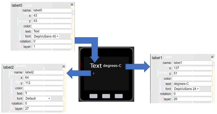
Figure 5.34 – Temperature sensor simulator monitor UI layout
You will use the Blockly code shown in Figure 5.35 to activate your temperature sensor simulator monitor.

Figure 5.35 – Blockly code for the temperature sensor simulator with a monitor
By clicking the run button on the UiFlow taskbar and adjusting the slide dimmer control, you will see a range of temperature values displayed on the M5Stack Core’s TFT LCD. Figure 5.36 illustrates the operation of the temperature sensor simulator.
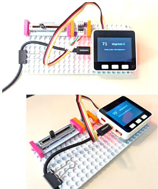
Figure 5.36 – Temperature sensor simulator with a monitor in operation
As you adjust the slide dimmer control, the LED bars will turn on upon exceeding the preset temperature value programmed within the Blockly code. Congratulations on building a temperature sensor simulator with a monitor! The final project you will build in this chapter is a littleBits LED flasher.
An M5Stack controller littleBits LED flasher
In this final project, you will learn how to wire a littleBits LED bar graph electronic module to the M5Stack Core. You will improve the interactive emoji UI discussed in Chapter 3. You will then obtain knowledge and skills in creating an aesthetically appealing visual animated display in this final project. Further, this final project will elucidate the key concept of using a block diagram with supporting electrical wiring diagrams and assembly pictures to assist you in building the LED flasher. The intention behind this learning and instructional approach is to allow you to assess the hands-on skills and technical knowledge you obtained from previous projects to build an M5Stack Core product. Therefore, you can think of this project as a capstone that allows you to assess and demonstrate your new knowledge and skills in building portable and interactive electronics using the M5Stack Core to your family, friends, and professional colleagues. Figure 5.37 illustrates the littleBits LED flasher concept.

Figure 5.37 – Concept diagram for the littleBits LED bar graph LED flasher
You will notice that the UI layout has two illustrated faces – a happy and a sad one. You can turn on the LED bar graph by pressing the ON push button. The M5Stack Core’s second pushbutton, or the B button, will turn on the LED bar graph. The happy face emoji will be displayed, along with the LED bar graph. The M5Stack Core’s third pushbutton, or the C button, will turn off the LED bar graph. A sad face emoji will be displayed on the M5Stack Core’s TFT LCD. You can start the flashing sequencing of the LED bar graph by pressing the M5Stack Core’s first pushbutton, or the A button. The happy and sad face emojis will toggle, along with the flashing LED bar graph. You can find the happy and sad face images on GitHub here:
https://github.com/mrdon219/https-github.com-PacktPublishing-M5Stack-Electronic-Blueprints
You will attach the LED bar graph using the littleBits bit snaps. The bit snaps allow the proto module and the LED bar graph to be magnetically and electrically attached to each other. The repulsive nature of the bit snaps lets you know when an attachment is incorrect – and a simple reversal will correct the assembly issue. Figure 5.38 illustrates the proper orientation and assembly of the LED bar graph to the proto module. You will use the diagram to correctly attach the M5Stack electrical jumper harness to the proto module.
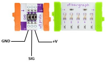
Figure 5.38 – Proper attachment and orientation of the littleBits LED bar graph to the proto module
Figure 5.39 provides further details on the electrical attachments of the jumper wire harness to the proto module to assist with correct assembly:
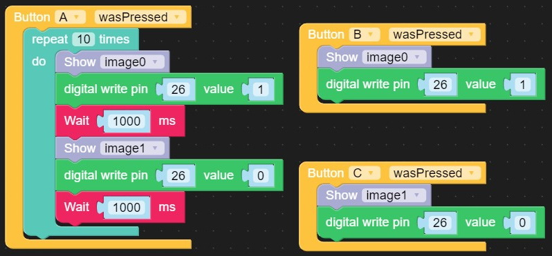
Figure 5.39 – Assembly of the jumper harness to the proto module
With the jumper harness attached and wired to the littleBits proto module, you can insert the white connector into the B port of the M5Stack Core. Place the littleBits electronic modules onto the plastic mounting plate to ensure proper electrical interfacing and mechanical rigidity are maintained during use. You can use the Blockly code to enable the LED flasher and the interactive emojis. Build the LED flasher Blockly code using Figure 5.40 as a reference. Click on the run button on the taskbar with your mouse to engage with the LED flasher. Figure 5.41 illustrates the M5Stack Core product in action.
Interactive quiz 5
Modify the Blockly code shown in Figure 5.40 so that a counter is displayed to keep track of the number of LED flashes.

Figure 5.40 – The LED flasher Blockly code
Here are some pictures of the assembled and operational littleBits LED flasher.
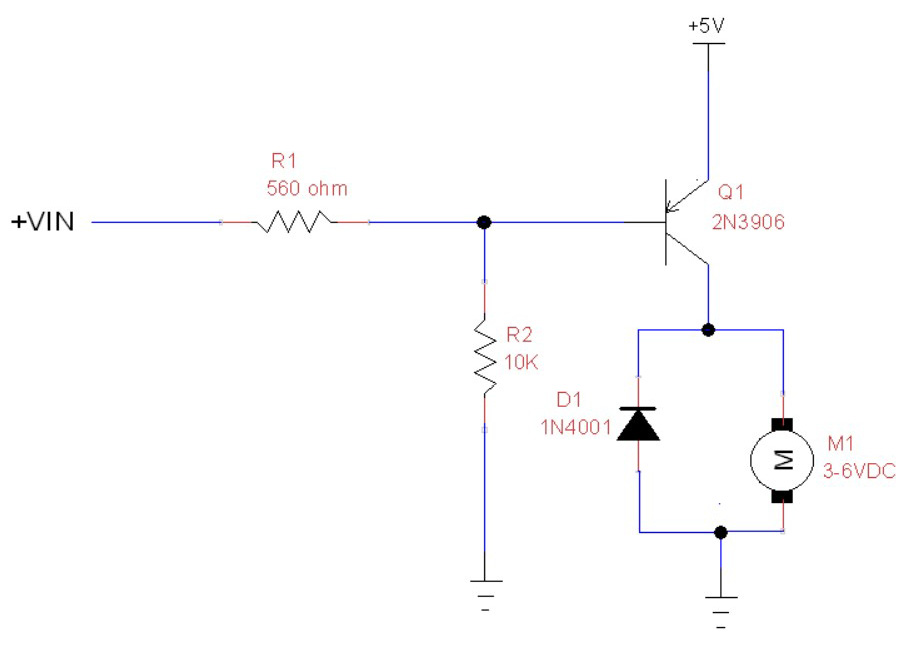
Figure 5.41 – The operational LED flasher device
Congratulations – you have successfully completed the M5Stack Core controller littleBits LED flasher project!
Summary
Congratulations – you have completed the hands-on activities and interactive quizzes in this chapter. In the chapter, you learned about the electronic circuits used to interface or connect discrete components to the M5Stack Core. You learned how to wire electronic circuits using solderless breadboards and proto modules. You learned how to build a virtual online circuit using Tinkercad Circuits to test a transistor LED driver circuit. You learned how to use a solderless breadboard to wire and test a transistor-operated DC motor. You learned how to create a physical simulator to behave like a temperature sensor using a littleBits slide control. When building a physical simulator, you learned about the NTC and its application with a thermistor.
Further, you learned how to use your coding skills and electronics knowledge to build a littleBits LED flasher. This project provided the concept diagram and the hardware and software components for building the M5Stack Core controller littleBits LED flasher. This project was different in its instructional approach, whereby you were assessed on the hands-on skills and technical knowledge obtained from previous chapters by building a functional and interactive product.
In this next chapter, you will take this knowledge of building an M5Stack Core controller to enable discrete solderless breadboard electronic circuits to work with an Arduino.
Interactive quiz answers
- Interactive quiz 1: Number 2
- Interactive quiz 2: Image
- Interactive quiz 3: Yes
- Interactive quiz 4: Yes
- Interactive quiz 5: Image
Quiz answers
Quiz 1: False
Quiz 2:
Total = I1 + I2
Total = (7.61 + 5.47) mA
Total = 13.08 mA (the correct value, so yes, they are correct)
Quiz 3: Text
Quiz 4: Single general-purpose, low-voltage, rail-to-rail output operational amplifier – LV321