
8
Working with the M5Stack and Wi-Fi
You learned about various approaches to wiring an M5Stack Core 2 to create different Bluetooth devices in Chapter 7. The ESP32 Microcontroller Bluetooth chipset was discussed in detail using a system architecture block diagram. A Bluetooth messaging device was built to explore the capabilities of the UiFlow BLE UART coding block pallets. Understanding the versatility of the coding blocks in allowing wireless control with the ESP32 Bluetooth chipset will help you use Wi-Fi technology in this chapter on Wi-Fi.
In this chapter, you will obtain hands-on skills and knowledge in Wi-Fi technology as it aligns with the IoT. You will explore hands-on approaches to using the M5Stack Core as a Wi-Fi receiver and controller to see networked wireless devices and operate them with a smartphone. You will learn how to create a wireless access point (WAP) with the M5Stack Core to control a Snap Circuits Bicolor LED. Furthermore, you will be introduced to the M5Stack Core application programming interface (API) by reviewing the C++ syntax. You will learn more about the M5Stack Core API by enhancing the existing C++ code.
The electronic circuit interfacing techniques that you learned about in Chapter 4 and Chapter 5 will be used in this chapter to build a WAP controller. You will investigate the operation of a Python-based Wi-Fi scanner project packaged with the UiFlow firmware, version 1.7.5. This hands-on investigation will provide context for the C++ version in which you will enhance its visual appeal. Before its visual enhancement, you will be introduced to developing C++ code on an M5Stack Core with a Hello World application.
By the end of this chapter, you will have learned how to carry out the following technical tasks with the M5Stack Core and Wi-Fi technology:
- Draw a system block diagram of an ESP32 Wi-Fi application
- Set up the M5Stack Core controller to access a wireless home network
- Develop and test a Wi-Fi scanner device using the M5Stack Core controller
- Develop and test a Wi-Fi scanner device with an LED indicator using the M5Stack Core controller
- Develop and test a Wi-Fi-based WAP and web server using an M5Stack Core controller
In this chapter, we are going to cover the following main topics:
- An introduction to Wi-Fi with the ESP32
- Wi-Fi setup for the M5Stack Core controller
- Detecting Wi-Fi networks with an M5Stack Core scanner – part 1
- Detecting Wi-Fi networks using an M5Stack Core scanner with an LED indicator – part 2
- Creating a WAP and a web server with an M5Stack Core controller
Technical requirements
To engage with the chapter’s learning content, you will need the M5GO IoT Starter kit to explore Wi-Fi IoT technologies. You will be introduced to the M5Burner to download and install firmware onto the ESP32 microcontroller-based controller. Further, the Arduino integrated development environment (IDE) software with the M5Stack library will be required to build and run the M5Stack Core Wi-Fi applications.
You will require the following:
- The M5GO IoT Starter kit
- The M5Burner software
- The Arduino IDE software
- The M5Stack library
- The M5Stack Arduino API
- A Snap Circuits Bicolor LED
- Snap Circuits electrical jumper wires
- A standard four-connector-based jumper wire harness
- A smartphone
Here is the GitHub repository for the software resources: https://github.com/PacktPublishing/M5Stack-Electronic-Blueprints/tree/main/Chapter08
An introduction to Wi-Fi with the ESP32
The M5Stack Core ESP32 microcontroller’s Wi-Fi system architecture consists of two subsystems: Wi-Fi media access control (MAC) and the baseband. The Wi-Fi MAC address is a unique identifier that is assigned to a network interface controller (NIC). The NIC allows us to address the network used in the Wi-Fi-based communication system. The MAC address for the M5Stack Core controller is shown in Figure 8.1:

Figure 8.1 – The M5Stack Core MAC address
The Wi-Fi baseband in a communication system is the modulating signal or intelligence sent through a single channel. The intelligence or digital data stream is sent through as the information through a single channel media. Wi-Fi baseband communication uses bidirectional communication transmitted through the single channel media to send and receive digital data. Figure 8.2 illustrates the ESP32 communication system block diagram.

Figure 8.2 – A block diagram for the ESP32 communication system
As observed, the ESP32 Wi-Fi subsystem blocks align with the Bluetooth link controller and the Bluetooth baseband. In general, the ESP Wi-Fi subsystem blocks implement transmission control protocol/internet protocol (TCP/IP) and the full 802.11 b/g/n Wi-Fi MAC protocols. TCP/IP is a seven-layer model that describes the ESP32 microcontrollers’ interaction with a communication network. Therefore, TCP/IP describes the function of the 802.11 b/g/n Wi-Fi MAC protocols. You now know about ESP32 Wi-Fi communication. In the next section, you will learn how to set up the M5Stack Core’s Wi-Fi.
Quiz 1
___________ or digital data stream is sent through as information.
Wi-Fi setup for the M5Stack Core controller
In this section, you will learn how to set up Wi-Fi for the M5Stack Core controller by adding the appropriate libraries to the Arduino IDE. The appropriate libraries are the M5Stack Core C++ files. These files will have the coding resources to allow your M5Stack Core controller to connect with a home Wi-Fi network. To obtain access to M5Stack Core libraries, read the installation instructions at the following website: https://docs.m5stack.com/en/quick_start/m5core/arduino. On this website, you will find instructions on installing the Arduino IDE with M5Stack Core libraries. Be sure to include the M5Stack Core 2 libraries during the selection and installation of the C++ files. With the installation complete, you will find a variety of coding projects and examples to explore within the Arduino IDE using the M5Stack Core. The projects and examples of interest will be the Wi-Fi projects. Figure 8.3 presents the M5Stack Core Wi-Fi coding projects and examples:

Figure 8.3 – M5Stack Core Wi-Fi projects and examples
After completing the installation steps presented in the Arduino M5Stack Core online article, you will perform a simple coding exercise. This coding exercise is a mini tutorial on programming the M5Stack Core using the C++ language. Therefore, you will go to the Arduino website to obtain the Arduino API information for the M5Stack Core. The Arduino API website is located here: https://docs.m5stack.com/en/quick_start/m5core/arduino.
The mini-C++ tutorial lesson consists of programming the M5Stack Core to display Hello World on the TFT LCD. As seen, an explanation of each line of code is provided for the M5Stack Core TFT LCD operation. Figure 8.4 is the Hello World mini tutorial lesson:

Figure 8.4 – The C++ Hello World code
Open the Arduino IDE and create a new file called Hello World. Create a folder on your hard drive with the same name. Save the C++ application in the folder just created. Next, begin typing the code into the editor. For convenience and ease, you can copy the code from the Arduino IDE M5Stack Core web page. With your mouse, scroll down to you see the section titled Hello World. Before uploading the code to the M5Stack Core, you can see the code structure. If you are familiar with the Arduino IDE, the programming structure is the same except for the M5.object.function instruction.
This new programming instruction is from the M5Core API library. The library is imported into the Arduino code using the # include <M5Stack.h> programming header. The programming header provides all the physical features of the M5Stack, which include the GPIO, speaker, system, RGB LED, buttons, and IMU. To initialize or start the M5Stack Core power module, the M5.begin() and M5.Power.begin() programming instructions are needed to ensure the M5Stack Core will operate properly. The M5.Lcd.print instruction will display Hello World on the TFT LCD. To ensure the text can be seen from a reasonable distance on the M5Stack Core TFT LCD, the M5.Lcd.setTextSize(2) programming instruction is used. You will include this coding instruction below the M5.Lcd.print code. The line number will be 13 for inserting the new programming instruction. Figure 8.5 illustrates the location of the new code:

Figure 8.5 – The location of the M5.Lcd.setTextSize(2) code instruction
To upload the Hello World code to the M5Stack, you will select the M5Stack as the controller board and its COM port. The uploading step is the same as for adding application code to the Arduino Uno. The selection of the M5Stack Core and the COM port is illustrated in Figure 8.6.

Figure 8.6 – Selection of the M5Stack Core and COM port
Interactive quiz 1
Is the Hello World text visible when using the M5.Lcd.setTextSize(4) instruction?
The final step is to upload the Hello World code to the M5Stack Core controller. Click on the Upload button identified by the arrow on the taskbar. The compilation process will begin and end by displaying the text on the M5Stack Core’s TFT LCD. Figure 8.7 illustrates Hello World being displayed on the M5Stack Core’s TFT LCD.
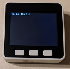
Figure 8.7 – Hello World
Congratulations on completing the mini C++ tutorial. You now have the knowledge and the skill to use the Arduino IDE to install a C++ application onto the M5Stack Core controller. The knowledge and skills learned will allow you to upload a mobile-based app to configure the Wi-Fi on the M5Stack controller.
With your mobile phone, you will install the EspTouch app. The EspTouch app allows you to configure and attach a home network to the ESP32. This mobile phone app will allow the M5Stack Core controller to detect your home network. The home network contents, such as the IP and Received Signal Strength Indicator (RSSI), will be displayed on the M5Stack Core controller’s TFT LCD. The diagram provided in Figure 8.8 illustrates this wireless signal detection scheme.
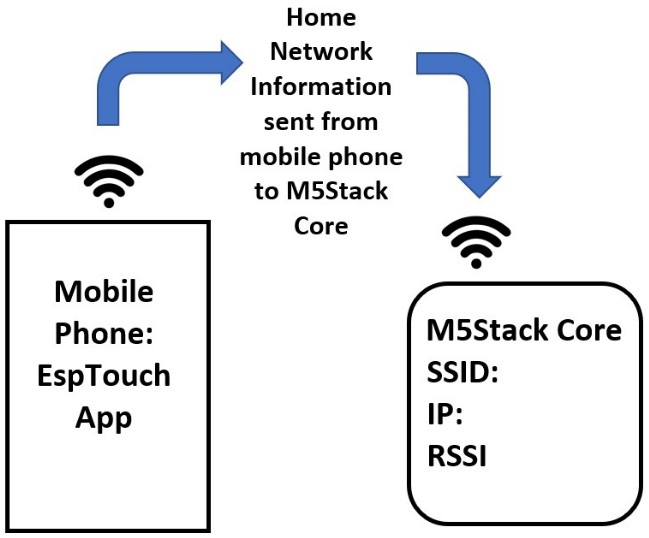
Figure 8.8 – A wireless signal detection approach
With this setup scheme, a portable remote Wi-Fi network monitor device can be realized. To obtain the EspTouch app (the app logo is a red-colored WiFi symbol and in iOS, the app name is Espressif Esptouch), go to the Apple store or the Google Play store. Once the app has been found, select it from the list of apps, and install it on your mobile phone. Open the EspTouch app to display the start screen. You will see EspTouch and EspTouch V2 on the screen: select EspTouch:

Figure 8.9 – EspTouch app home screen
After selecting EspTouch, the following screen shown in Figure 8.10 will be presented.
Note
RSSI is a measurement of the wireless device’s capability to receive a signal from an access point or router.

Figure 8.10 – The EspTouch Start screen
You will see your Service Set Identifier (SSID) number and the Basic Service Set Identifier (BSSID) of your home network. With the app open on your mobile phone, you will proceed to upload the WiFiSmartConfig.ino software onto the M5Stack Core. You will find this software by selecting File | Examples | M5Stack | Advanced | WiFi | WiFiSmartConfig within the Arduino IDE. Figure 8.11 illustrates the selection steps presented.
Note
SSID is the name of the Wi-Fi network. The BSSID is the MAC physical address of the access point or wireless router that is used by the network to connect to the Wi-Fi.
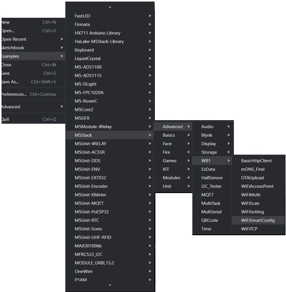
Figure 8.11 – Selecting the WiFiSmartConfig.ino application
You can upload the WiFiSmartConfig.ino code using the previous steps illustrated in Figure 8.6 to the M5Stack Core. Figure 8.12 shows the partial code for the WiFiSmartConfig.ino wireless application. The original text font size is 1. Add the M5.Lcd.setTextSize(2) instruction before each M5.Lcd.print() line of code to make the text readable on the TFT LCD. Figure 8.13 illustrates this code modification step. This step will allow some experimentation with the UI layout design to align with readability. The exploration with the M5.Lcd.setTextSize(2) instruction will demonstrate the importance of creating UI layouts that make text readable. Making code improvements will allow you to experiment with the TFT LCD using C++ code:
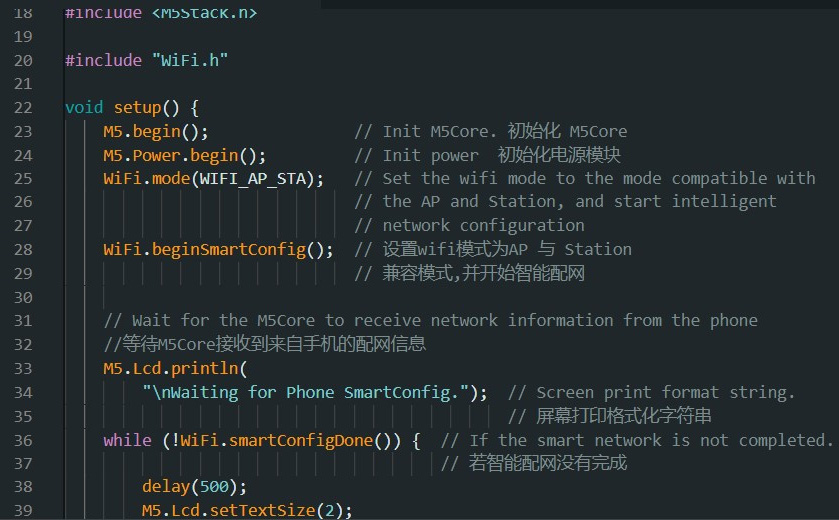
Figure 8.12 – Partial WiFiSmartConfig.ino application code

Figure 8.13 – Improving the text font size with M5.Lcd.setTextSize(2)
You will tap the device count box within the EspTouch app. Enter 1 into the box and check the checkbox on your mobile view. Touch the Start button at the bottom of the EspTouch app. Touch ok when the EspTouch app displays the BSSID number. Press the power button on the M5Stack Core. Within a few seconds, you should see your home network’s IP and the RSSI information displayed on the M5Stack Core. Figure 8.14 illustrates the completed step. Congratulation on capturing your Wi-Fi setup information using the M5Stack Core. In this next section, you will continue your Wi-Fi investigation by building a handheld wireless scanner.

Figure 8.14 – Home network information displayed on the M5Stack Core
Note
Make sure the M5Stack is in internet mode and on the same WiFi as the phone or tablet.
Detecting Wi-Fi networks with an M5Stack scanner – part 1
You have seen that the M5Stack Core has a Wi-Fi subsystem consisting of a baseband and MAC electronic circuits. To aid these hardware elements, the software allows the configuration of these circuits with the ESP32 microcontroller core subsystem. The M5Stack Core will allow us to assess a home Wi-Fi network displayed on a 2-inch TFT LCD. The application detection code will help the M5Stack Core cohesively stitch the Wi-Fi circuits to the ESP32 core subsystem. This is all achieved using the Wi-Fi scan code found within the Arduino IDE examples. You will use the M5Stack Core example WiFiScan code to assess and display the wireless networks within your home. To access the C++code, select File | Examples | M5Stack | Advanced | WiFi | WiFiScan with your mouse. Figure 8.15 shows the selection sequence for obtaining the WiFiScan code:

Figure 8.15 – Obtaining the WiFiScan code
Upon opening the WiFiScan code within the Arduino IDE, you will notice the default font size within the software listing. To improve the readability of the fonts, the M5.Lcd.setTextSize(2) instruction will be used. Figure 8.16 illustrates the partially improved WiFiScan code.
Interactive quiz 2
What is the maximum acceptable font size to use for improving the readability of the SSID and RSSI data?
The usability of the M5Stack Core controller will be improved by making the font size readable. The default text size requires an element of magnification so that the text can be read. Again, the M5.Lcd. setTextSize() instruction will improve this usability concern:
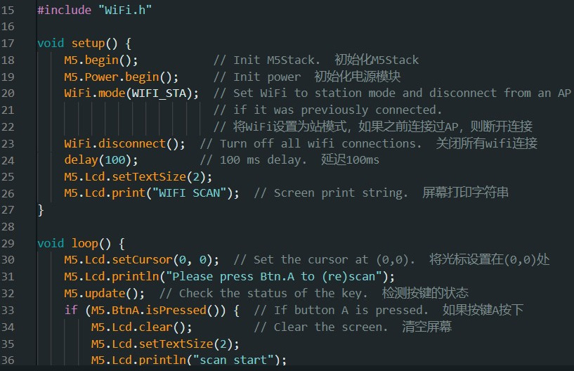
Figure 8.16 – Improved readability for WiFiScan
After the modifications have been made to the WiFiScan C++ code, you can upload the software to the M5Stack Core. The code will be compiled and then uploaded to the M5Stack Core’s ESP32 microcontroller. Once the code is uploaded to the M5Stack Core, the Please press Btn.A to(re)scan message will be displayed on the TFT LCD. Figure 8.17 shows the text displayed on the TFT LCD.
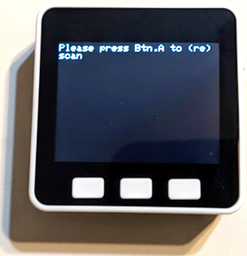
Figure 8.17 – The WiFiScan code running on the M5Stack Core
When you press Button A to start the scan, the Wi-Fi networks within your home will be displayed on the M5Stack Core’s TFT LCD. The RSSI data for each network will be displayed as well. You can repeat the scan by pressing Button A. Congratulations – you have successfully programmed the M5Stack Core to scan and display wireless networks in your home.
Another version of a Wi-Fi scanner that you can evaluate through experimentation is within the M5Stack Core’s firmware. To obtain the Wi-Fi scanner, the M5Burner software must be used. The M5Burner software can be obtained from here: https://docs.m5stack.com/en/download. The M5Burner software is available for Windows, macOS, and Linux operating systems (OSes). Figure 8.18 shows the available M5Burner software for the listed OSes.

Figure 8.18 – The M5Burner firmware software
You will download the appropriate software for a desktop personal computer (PC) or laptop computer OS. Install it and open the M5Burner firmware software. With the software open, click the down arrow and select v1.7.5 from the drop-down list box located on the right. Click on the Burn button to start the installation of the 1.7.5 firmware version onto the M5Stack Core. Figure 8.19 illustrates the M5Burner firmware software. The M5Burner firmware software, once installed on the M5Stack Core, will reset the device automatically.
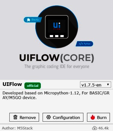
Figure 8.19 – M5Burner software
Interactive quiz 2
Using Figure 8.16, modify the WiFiScan code to start the scan with the Button B input control.
Once the firmware has been installed, the UiFlow splash screen will appear on the TFT LCD. To obtain the Wi-Fi scanner application, press Button A (the APP icon) to view the list of MicroPython applications. A partial list of MicroPython applications is shown in Figure 8.20.
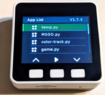
Figure 8.20 – M5GO MicroPython applications
You will use the down arrow located above Button C to scroll to the wifi_scaner.py application:
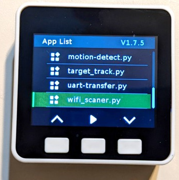
Figure 8.21 – M5GO MicroPython wifi_scaner application
Select the application by pressing Button B on the M5Stack Core. Upon making this selection, the Wi-Fi scanner will immediately list the wireless networks within your home. The scan will continue to repeat the search and display function. You can stop this wireless scan operation by pressing the ON power button once. This step will turn off the M5Stack Core controller, thus allowing the startup of the Wi-Fi scanner. The next stage in the Wi-Fi scanner development is to provide visual feedback.
Detecting Wi-Fi networks with an M5Stack scanner with an LED indicator – part 2
You have investigated two Wi-Fi scanner designs using the M5Stack Core controller. The first Wi-Fi scanner design allowed you to manipulate the C++ code to change the text font size. The second Wi-Fi scanner design provided a quick method to assess your wireless home networks. Having gone through these two design approaches, you now have the knowledge and technical skills to enhance the Wi-Fi scanner. The enhancement will require adding an LED indicator. To make this physical visual feature improvement to the Wi-Fi scanner, a software modification is needed. The concept for the Wi-Fi scanner with an LED indicator is shown in Figure 8.22:
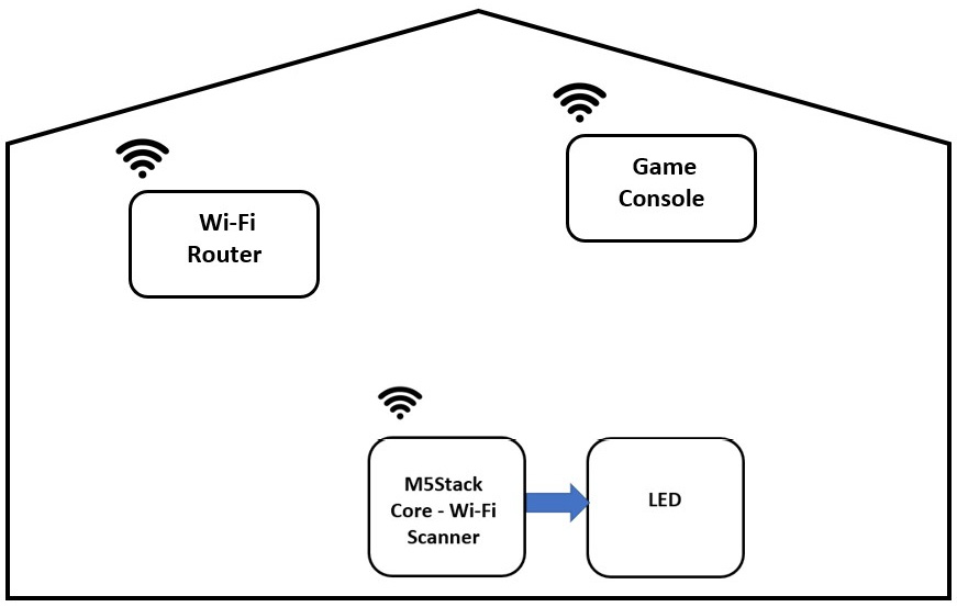
Figure 8.22 – A Wi-Fi scanner with an LED indicator
The diagram illustrates a home network in which the LED provides a visual indication of detecting wireless devices. The M5Stack Core Wi-Fi scanner that we investigated in the first activity provided IP and RSSI information on the TFT LCD. The electronic scanner seamlessly connects to the home network using a Wi-Fi baseband subcircuit. The LED provides a visual indication of the Wi-Fi scanner completing its scan of wireless devices detected within a home network. Upon starting a new scan, the LED will be off.
Therefore, this project is developed with two parts: hardware and software. The hardware development consists of wiring an LED circuit to the M5Stack Core controller. Port B has a digital output pin (G26) that allows you to connect external circuits for control. You will wire the LED circuit to this digital output pin to provide a visual indication of the completed scan of wireless devices connected within a home network. You will use the electronic circuit schematic diagram in Figure 8.23 to wire the LED circuit to port B’s G26 digital output pin.

Figure 8.23 – Electronic circuit schematic diagram for a Wi-Fi scanner with an LED indicator
Although Figure 8.23 shows discrete electronic components wired in series to a digital pin, G26, a Snap Circuits LED may be used. The Snap Circuits LED component, D10, is a bicolor component. Reversing the voltage source across the bicolor LED provides two unique colors. The Snap Circuits LED component will emit a red- or yellow-colored light based on the reversal of an applied voltage source. Therefore, the output color indication of the scanned Wi-Fi network-connected devices can be changed by the reversal of port B’s G26 digital pin and the electrical ground. Figure 8.24 shows the two electronic circuit schematic diagrams for emitting red or yellow light from the bicolor LED:

Figure 8.24 – Electronic circuit schematics for red or yellow emission of light with a bicolor LED
You will use the four-wire electrical jumper harness attached to the Snap Circuits bicolor LED component. Using the Snap connectors, you can make reverse the wires between the bicolor LED and the M5Stack Core controller conveniently and easily. Figure 8.25 illustrates a four-wire electrical jumper harness attachment between the M5Stack Core controller and the Snap Circuits bicolor LED component.
Quiz 2
Reviewing the two electronic circuit schematic diagrams shown in Figure 8.24, which circuit will allow the bicolor LED to emit red light via the M5Stack Core controller?
a) The top circuit
b) The bottom circuit
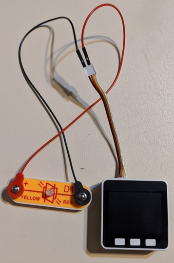
Figure 8.25 – Snap Circuits bicolor LED component attached to an M5Stack Core controller
With the two electronic circuit schematic diagrams presented, you will be able to test the bicolor LED of the Snap Circuits component quite easily. The hardware portion of this Wi-Fi scanner modification activity is completed. The final step requires the inclusion of digital output port B pin, G26, to operate the bicolor LED in the Wi-Fi scanner C++ code. The C++ code modification will use the traditional digitalWrite() and pinMode() Arduino Uno programming instructions.
Interactive quiz 3
With the two electronic circuit schematic diagrams presented in Figure 8.24, is it possible to provide an audible alarm status indicator with a piezo buzzer?
The first modification to the Wi-Fi code is setting G26 as the digital output pin of port B. To accomplish this coding task, the pinMode( ) instruction is used. The void setup( ) function is the part of the C++ code in question. Figure 8.26 shows the inclusion of the pinMode( ) instruction when establishing G26 as a digital OUTPUT pin within the void setup( ) function:

Figure 8.26 – Defining pin G26 as OUTPUT
With port B set up as a digital OUTPUT pin, you use it to turn on the Snap Circuits bicolor LED component. The Arduino C++ code instruction to use is digitalWrite( ). The bicolor LED will turn on after the complete scan of the wireless network and display them on M5Stack Core’s TFT LCD. The line number at which to include the digitalWrite(26,1) instruction is shown next.

Figure 8.27 – Code location to turn on the G26 digital pin
The bicolor LED will turn off when Button A on the TFT LCD is pressed. The bicolor LED will also turn off when there are no discovered scanned Wi-Fi devices or networks. Figure 8.28 shows the location of the digitalWrite(26,0) instruction to include in the Wi-Fi scanner code:
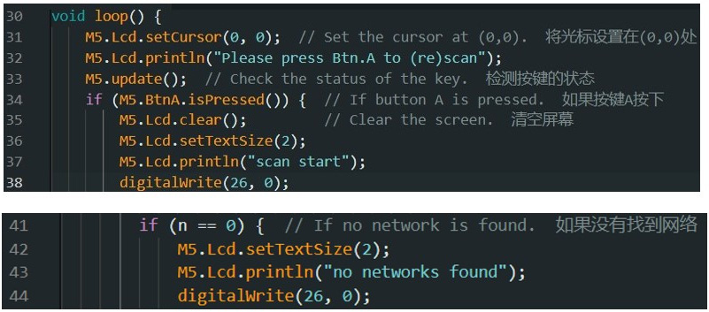
Figure 8.28 – Turning off the bicolor LED with the digitalWrite(26, 0) instruction
As captured in the C++ code snippets, the value of 2 establishes the text size for the Wi-Fi scanner application. The M5.Lcd.setTextSize( ) instruction has a numerical range of 0 to 7. As a UI layout design usability experiment, try finding the optimal text size by changing the parameter’s value. Record the value to use in future M5Stack Core controller projects. Further, replace the Snap Circuits bicolor LED component with an RGB unit to give a new look to detecting the wireless devices and networks in the home. You will now complete the final project of this chapter: creating a WAP and a web server with an M5Stack Core controller.
Quiz 3
If the following lines of code are provided for an external wired LED during a completed wirelessly network scan, what is the visual effect?
digitalWrite(26,1);
delay(500);
delayWrite(26,0);
delay(500);
Creating an access point and web server with an M5Stack Core controller
In this final chapter project, you will build an access point and web server using an M5Stack Core controller and a smartphone. You will use the M5Stack Core to create an access point to connect and control a wireless device. The WAP will be accessible with an SSID and URL network address. The smartphone will allow access to the wireless network by connecting to the M5Stack Core 2 WAP SSID. The result is connecting to a web server that allows you to control an external device wired to an M5Stack Core controller. The concept for the WAP and web-server-based controller is shown in Figure 8.29.

Figure 8.29 – Use case model concept for the WAP web server controller
The user will touch the mobile phone screen to interact with the web page UI controls. The web server web page UI controls allow a simple ON/OFF control capability. The M5Stack Core WAP controller receives the ON/OFF commands from the web server web page based on the network established from the web server and the M5Stack Core WAP controller. The M5Stack Core WAP controller will turn the wire-controlled device on and off. Small electromechanical loads such as motors and solenoids, LEDs, transistor relay circuits, and piezo buzzers are examples of controlled devices. The use case model presented in Figure 8.29 can be modified to show an electronic circuit schematic diagram of the M5Stack Core WAP controller. Figure 8.30 illustrates the new WAP web server controller diagram. In this diagram, additional details have been added as they relate to the controlled device circuit components. This basic electronic circuit diagram presents the concept of the M5Stack Core as a practical and functional controller capable of operating a variety of discrete visual, audible, and electromechanical actuator loads. The knowledge and skills obtained in previous chapters exploring interfacing concepts using littleBits electronic modules, Snap Circuits, and Arduino will be applied in the operational scheme of this controlled device.
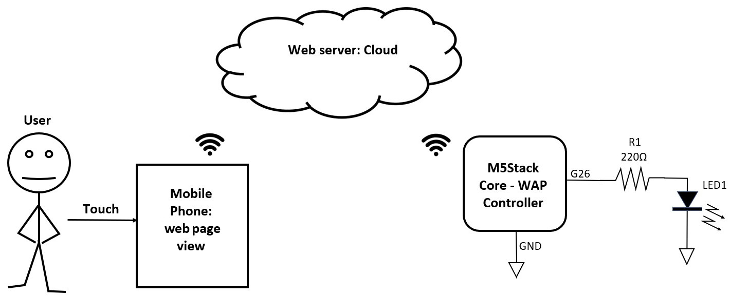
Figure 8.30 – Detailed WAP web server controller diagram
The M5Stack Core WAP controller is the electronic circuit schematic diagram illustrated in Figure 8.24 to provide a completed Wi-Fi network scan. To explore the configuration of this WAP controller’s wiring method, Figure 8.31 expands on port B and its alignment with the G26 output and attachment to the M5Stack Core. Another important element regarding port B and the jumper harness is the identification of the G26 output pin:

Figure 8.31 – Port B connector pinout
As noted in Figure 8.31, the colored wire associated with port B’s G26 digital pin is yellow. The key identifier of the G26 pin is its physical location on the male connector. G26 is in the third position within the male connector’s construction. With this information, the color of the wire is not the true indicator of the digital control signal presence but the pin location. The four-conductor jumper wire harness color scheme regarding yellow and white can be switched. Figure 8.32 illustrates this important fact of the reversal of color wire positioning among the two four-conductor jumper wire harness variants:

Figure 8.32 – Location of the G26 digital pin
As illustrated in Figure 8.32, between the two jumper wire harness configurations, what is consistent is the location of the G26 digital pin. You now have a further understanding of the alignment of port B and the physical location of the G26 digital pin. Another design practice to consider as it relates to the electrical wiring of specialized electronic circuits is the development of the system block diagram.
The system block diagram is an important design tool when developing controlled devices for the M5Stack Core WAP controller. As illustrated in Figure 8.29 and Figure 8.30, the system block diagram was created with a two-level design approach. The first-level system block diagram, as presented, is conceptual, meaning very few details of specific component values and symbols are not provided. The second level system block diagram provides information on electrical and electronic component names and I/O port designators. Occasionally, electrical and electronic component names with symbol representation are provided in a second-level system block diagram. With the system block diagram you designed, the electrical-electronic interface circuits may be realized in a seamless matter.
You may now proceed to install the Wi-Fi AP software for the M5Stack Core WAP controller. The baseline C++ code to be used with the M5Stack Core controller is the WiFiAccessPoint.ino file. You will find this code by going to the following directory of File | Examples | M5Stack | Advanced | WiFi | WiFiAccessPoint. Figure 8.33 shows where to access the WiFiAccessPoint.ino file. You will use the Arduino IDE to access and open this code:
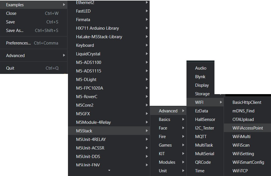
Figure 8.33 – Accessing the WiFiAccessPoint code
With the WiFiAccessPoint.ino file, you will use the code to build a framework for the M5Stack Core controller as an IoT development platform. You will improve the code by changing the text size. In the previous project, you use the M5.Lcd.setTextSize( ) instruction to allow the TFT LCD displayed information to be readable. Figure 8.34 illustrates the approach of including the M5.Lcd.setTextSize( ) instruction to improve the WiFiAccessPoint readability on the TFT LCD. You will add this coding instruction through the entirety of the WiFiAccessPoint code.
After completing this task, rename the program and save it. You now have created a software workspace in which further modifications can be carried out without damaging the original code. This approach is a good software development practice of ensuring the original code will be available as a reference to the application being developed:
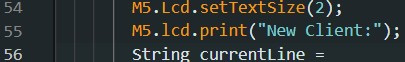
Figure 8.34 – Adding the M5.Lcd.sizeText() instruction for readability
With the text size changes added to the code, upload the software to the M5Stack Core controller. Add your SSID and password to the network you would like to connect with. The location within the code is shown in Figure 8.35.
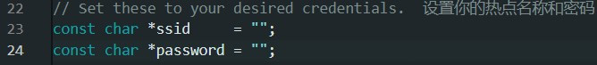
Figure 8.35 – Adding the Wi-Fi network login credentials
Attach the Snap Circuits bicolor LED to port B of the M5Stack Core controller. This task will be accomplished by using the four-wire jumper harness as the electrical connecting interface between the M5Stack Core controller’s port B and the Snap Circuits bicolor LED. Figure 8.36 illustrates the electrical connection of the controlled device (the Snap Circuits bicolor LED) to port B of the M5Stack Core controller. Turn on the M5Stack Controller by pressing the red power button located on the left side of the device.

Figure 8.36 – Connecting the Snap Circuits bicolor LED to the M5Stack Core controller
You will upload the modified code to the M5Stack Core controller. The upload process consists of checking syntax errors through code compilation. If there are no errors detected during the compilation event, the upload process will display a message as shown here:
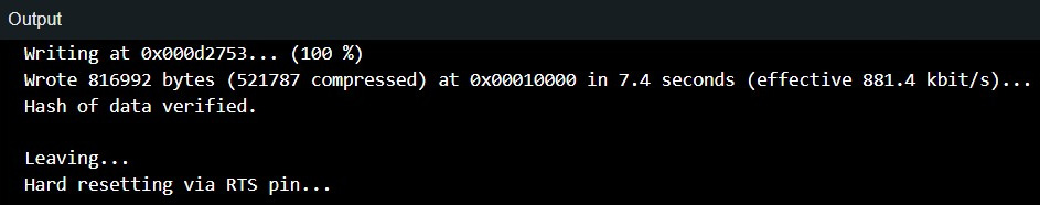
Figure 8.37 – Completed code compilation and upload to the M5Stack Core controller
You will see the SSID network name and the URL address to access the web server UI controls on the M5Stack Core controller TFT LCD. Figure 8.38 illustrates this step. Congratulations on completing this project task!
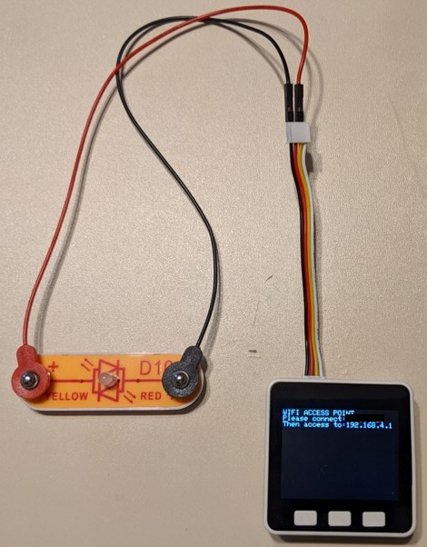
Figure 8.38 – The M5Stack Core controller connected to the UI control web server
Note
If this text size change illustrated in Figure 8.34 does not improve the readability of the displayed information, remove it from your code and save the file.
You will connect to the network SSID used in Figure 8.35 to obtain web server access using a smartphone. The M5Stack Core controller will provide a URL address to obtain the simple UI for operating the Snap Circuits bicolor LED with your smartphone. You will complete the final step of this project by including the digitalWrite(26,0) and digitalWrite(26,1) instructions for operating the Snap Circuits bicolor LED in the WiFiAccessPoint C++ code. You will use the pinMode(26,OUTPUT) instruction to set up the digital pin as an output driver to operate the Snap Circuits bicolor LED. Figure 8.39 provides the line number for inserting the pinMode(26,OUTPUT) instruction into the code:

Figure 8.39 – Defining G26 as an output digital pin
Figure 8.40 illustrates where the digitalWrite(26,0) and digitalWrite(26,1) instructions will be included in the WiFiAccessPoint C++ code:
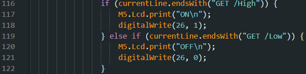
Figure 8.40 – Line number locations for inserting digitalWrite() instructions
Interactive quiz 3
Change the value of M5.Lcd.setTextSize( ) to 4. Did the new parameter improve the readability of the displayed text?
After adding digitalWrite(26,0) and digitalWrite(26,1) into the modified WiFiAccessPoint C++ code, upload the software to the M5Stack Core controller. You will then enter the URL address displayed on the M5Stack Core to access the web server UI LED controls into a web browser on the smartphone. Figure 8.41 illustrates the web server UI LED controls:
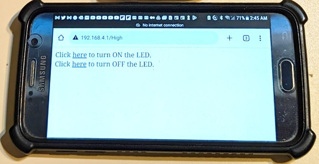
Figure 8.41 – Basic UI LED controls displayed on a smartphone
You will touch the Click here to turn ON the LED web server button with your finger. Upon completing this action on your smartphone, the M5Stack Core controller will turn on the Snap Circuits bicolor LED. Depending on the wiring configuration used (see Figure 8.24), the LED will emit red or yellow light. Figure 8.42 illustrates the task of turning on the LED using your smartphone. If the Snap Circuits LED does not turn on, make sure the four-jumper-wire harness is properly inserted into the M5Stack Core controller’s port B. Check the electrical snaps attached to the LED, along with the wires, which should be properly inserted into the jumper wire harness female connector ground and pin location 3 cavities. Finally, check to see whether you are attached to an SSID network on your smartphone. If these checks are completed, try operating the Snap Circuits LED with your smartphone.
Interactive activity
With the LED turned on, reverse the snap connections to display the other color.
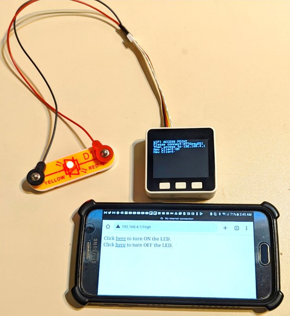
Figure 8.42 – The Snap Circuits bicolor LED operated by the WAP server
You will touch the Click here to turn OFF the LED web server button with your finger. Upon completing the action on your smartphone, the M5Stack Core controller will turn off the Snap Circuits bicolor LED. Depending on the wiring configuration used (see Figure 8.24), the LED will stop emitting either red or yellow light. Figure 8.43 illustrates the task of turning off the LED using your smartphone.

Figure 8.43 – The Snap Circuits bicolor LED operated by the WAP server
Again, if the Snap Circuits LED does not turn off, make sure the four-jumper-wire harness is properly inserted into port B of the M5Stack Core controller. Check the electrical snaps attached to the LED, along with the wires, which should be properly inserted into the jumper wire harness female connector ground and pin location 3 cavities. Finally, check to see whether you are attached to an SSID network on your smartphone. If these checks are completed, try turning off the Snap Circuits LED with your smartphone.
Summary
Congratulations – you have completed the hands-on activities and quizzes in this chapter. In this chapter, you learned about the ESP32 Wi-Fi subsystem architecture by analyzing a block diagram. With this knowledge of system block diagrams, you learned how to create one for developing an ESP32 Wi-Fi application. You learned how to set up the M5Stack Core controller to access a wireless home network. You developed and tested a Wi-Fi scanner device using the M5Stack Core controller. In analyzing a C++ code-based Wi-Fi scanner, you investigated the operation of a MicroPython-created network scanning device packaged with the M5Burner firmware software. Lastly, with the C++ skills obtained in creating a Wi-Fi scanner, you were able to develop, enhance, and test a WAP and web server to control a SNAP Circuits bicolor LED wired to the M5Stack controller with a smartphone.
Interactive quiz answers
Interactive quiz 1: Yes, the size is twice as large compared to M5.Lcd.setTextSize(2).
Interactive quiz 2: M5.BtnB.isPress( )
Interactive quiz 3: Yes, the ON/OFF control data is quite readable from several inches away.
Quiz answers
Quiz 1: The intelligence
Quiz 2: The bottom circuit
Quiz 3: The LED will flash on and off for 1 second.