
7
Working with M5Stack and Bluetooth
You learned various approaches to wiring an M5Stack Core2 to an Arduino Uno compatible in Chapter 6. The Freenove Projects kit allowed the prototyping of an M5Stack Core2 to an Arduino quite easily. In the previous chapter, you learned how to create an inverting switch using a digital quad NAND integrated circuit (IC) with an Arduino Uno compatible. Further, a touch control counter, with various controllers, was built using the M5Stack Core2 as the UI for the Arduino Uno compatible. The Freenove Projects kit allows rapid development of these interactive devices. As observed in Chapter 6, the transistor relay driver provided an automation switch approach to interacting with the Arduino Uno compatible.
Besides using an electromechanical relay method of control, an ADC interfacing approach using the M5Stack Core2, in the LED dimmer controller project, M5Stack Core2 provided varying DC voltages used by the Arduino Uno compatible’s analog-to-digital converter (ADC) channel. With such adjustable voltages, the M5Stack Core2 was able to change the Freenove Projects kit’s LED light intensity. The slider UI was introduced with this project, thus allowing you the opportunity to explore a new approach to creating unique electronic controller product engagement activities using the M5Stack Core2.
In this chapter, IoT projects will be explored using the M5Stack Core2’s Wi-Fi and Bluetooth chipsets. The intention of this chapter is to allow you to build unique wireless controllers using the ESP32 Bluetooth-embedded chipset. You will learn about Bluetooth Low Energy (BLE) technology by building wireless transmitters and receivers to operate RGB LEDs, sound-tone generators, and messenger devices. Further, you will learn how to work these wireless devices using a smartphone, tablet, or laptop computer.
By the end of this chapter, you will have learned how to perform the following technical tasks with M5Stack Core2 and BLE technology:
- Build an ESP32 BLE application
- Code and test an ESP32 BLE application
- Code and test a BLE transmitting device using the Nordic Semiconductor’s nRF toolbox
- Send M5Stack messages to a BLE terminal app
- Create a Nordic Semiconductor nRF toolbox touchscreen UI and test an M5Stack Core2 BLE receiver controller
In this chapter, we are going to cover the following main topics:
- The ESP32 microcontroller Bluetooth chipset
- UiFlow BLE coding blocks pallet overview
- Detecting an M5Stack Core2 Bluetooth signal with the Nordic Semiconductor nRF toolbox
- Building an M5Stack Bluetooth messenger device
- Building an M5Stack Bluetooth receiver controller
- Creating a Bluetooth RGB LED light and sound generator
Technical requirements
To engage with the chapter’s learning content, you will need the M5Stack Core2 to explore touchscreen controller applications and software coding of your UI designs. You will be introduced to the Nordic Semiconductor nRF toolbox for BLE detection and control applications. Further, the UiFlow Blockly code software will be required to build and run the M5Stack Core2 BLE controller applications.
You will require the following:
- M5Stack Core2
- Nordic Semiconductor nRF toolbox
- Transistor relay module
- Solderless breadboard
- Tactile pushbutton switch
- Active piezo buzzer
- Jumper wires
- Standard connector-based jumper harness
- Smartphone
- Tablet
Here is the GitHub repository for software resources:
https://github.com/PacktPublishing/M5Stack-Electronic-Blueprints/tree/main/Chapter07
The ESP32 microcontroller Bluetooth chipset
The M5Stack Core2 uses an ESP32-DOWDQ6-V3 microcontroller incorporating a 240 MHz, dual-core microprocessor. A dual-core microprocessor provides efficiency in computation and managing input/output (I/O) operations of the microchip using two central processing units (CPUs). Within this family of ESP32 microcontrollers, the chip has a Bluetooth chipset consisting of a link controller and baseband. The Bluetooth link controller handles the physical layer packets and all communication timing. The link controller implements the link, the low-level real-time protocol that operates Bluetooth communications. The baseband is the physical layer of Bluetooth communications. The baseband manages physical channels and uses other services in communication such as security and error correction. The baseband protocol or operating rule performs the link controller within the Bluetooth chipset. Figure 7.1 illustrates the Bluetooth chipset architecture:

Figure 7.1: ESP32 Bluetooth chipset architecture
The clock generator within the Bluetooth chipset architecture is an electronic oscillator that produces a repetitive signal for synchronizing the Bluetooth link controller with the baseband. The RF transmit circuit block allows sending a modulated signal with the appropriate carrier wave and intelligence data to a designated or paired receiver. The RF receive circuit is responsible for obtaining intelligence data from a demodulated designated or paired transmitter signal. The RF switch is an electronic device used to route the 2.4 GHz signal received from a designated or paired transmitter. Finally, the balun is an electrical device that converts an unbalanced modulated received signal into a balanced or differential demodulated waveform. Traditionally, the balun is wired to the Bluetooth antenna to achieve a differential or balanced load for RF signal integrity. The balun electrical circuit concept is shown in Figure 7.2:
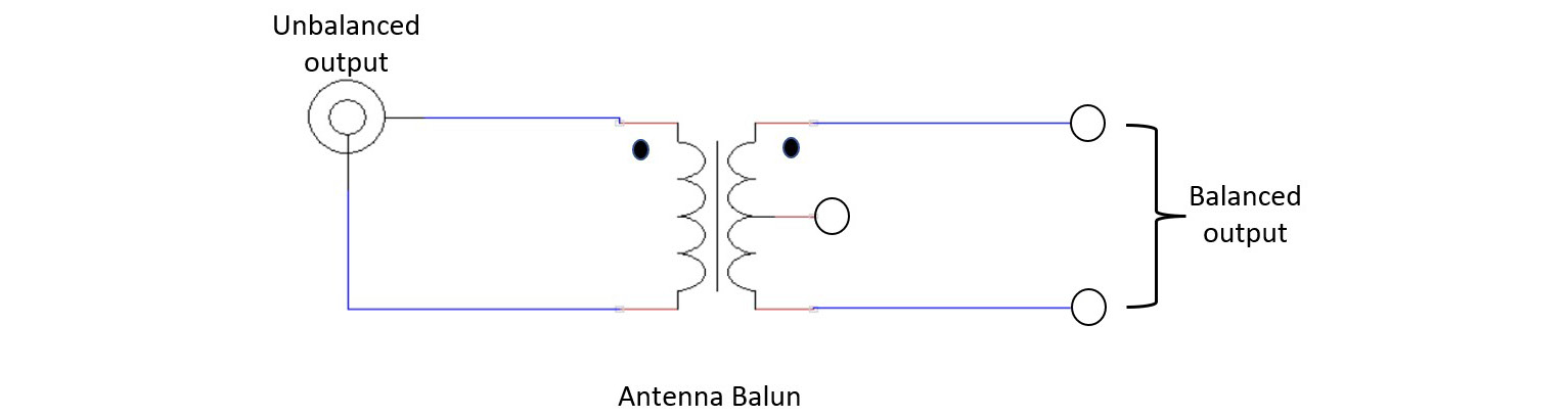
Figure 7.2: The antenna balun concept
Quiz 1
The clock generator is an electronic ________________.
With an understanding of the ESP32 Bluetooth chipset, you will explore the UiFlow BLE coding blocks pallet. The BLE coding blocks pallet provides the operational means of allowing intelligence data to turn on or off an M5Stack RGB LED unit or transmit a text message. Therefore, the next section will provide an explanation of the BLE Blockly code blocks.
UiFlow BLE coding blocks pallet overview
The BLE coding blocks within the UiFlow software align with the universal asynchronous receiver-transmitter (UART) operation domain. A UART is a microelectronics device capable of providing asynchronous serial communication with a configurable data format and transmission speeds. The method of formatting the communication data is through a parallel-serial conversion process provided by the UART. The UART transmits the communication data serially to a receiving UART. Upon the receiving UART obtaining the communication data, it sends the digital information back to the transmitting UART in a parallel format. To accomplish this parallel-serial conversion process among receiving and transmitting UARTs, transmit (Tx) and receive (Rx) pins are used. Figure 7.3 illustrates the physical wiring of the Tx and Rx pins of UART-based communication devices:

Figure 7.3: UART communications method
A final piece of information about the UART is data transmission without a digital clock. In synchronous communications, a clock allows for synchronizing digital system circuits sequencing simultaneously. In an asynchronous system, the digital system circuits are sequenced using start and stop bits. A data packet consisting of intelligence or information data with a start and stop bit allows the digital system circuits to operate in a uniform matter.
The UiFlow BLE Blockly coding blocks are centered on the UART for sending and receiving intelligence data packets. There are six primary BLE Blocky coding blocks within the pallet. Figure 7.4 illustrates these:
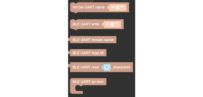
Figure 7.4: BLE-UART Blockly coding blocks
Here are descriptions for the BLE-UART Blockly coding blocks shown in Figure 7.4:
- Init ble uart name—Blockly code block used to initialize and configure wireless communication settings of the specified named Bluetooth device
- BLE UART write—Blockly code block used to send intelligence data using the BLE UART
- BLE UART remain cache—This Blockly code block is used to check the BLE UART number of data bytes
- BLE UART read—Reading the BLE UART cache data can be achieved with this Blockly code block
- BLE UART read characters—This Blockly code block allows reading the n-number of the BLE UART cache data
- BLE UART on recv—This Blockly code block allows decoding all BLE UART received data
Note
A cache (pronounced cash) is a hardware device or software element used to store data.
The primary UiFlow coding process of an M5Stack Core2 Bluetooth application using the BLE UART blocks consists of the following steps: initializing the BLE UART name, establishing the BLE UART conditional logic, and sending BLE UART data. To see the Blockly coding implementation of this process, you will begin by accessing the BLE UART pallet within the UiFlow software. The location of the pallet is shown in Figure 7.5:
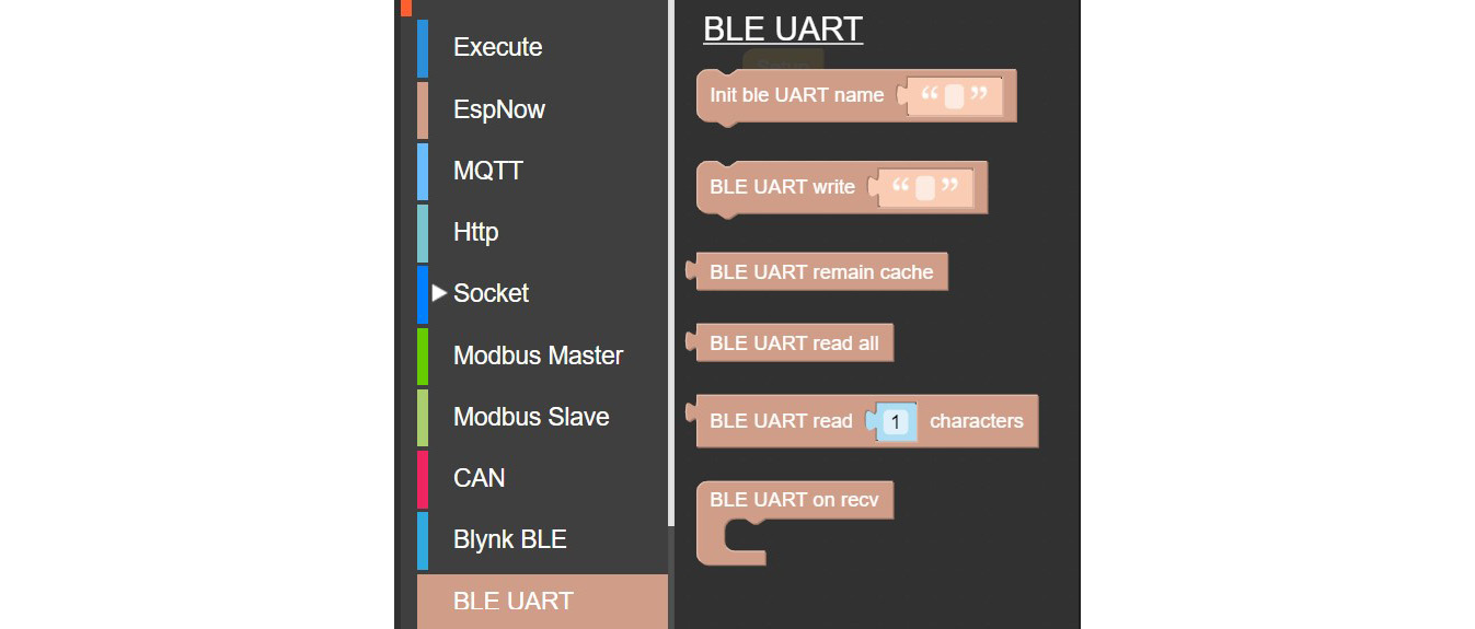
Figure 7.5: Accessing the BLE-UART Blockly code block pallet
You will then select BLE-UART Blockly code blocks from the pallet to build your specific Internet of Things (IoT) application within the UiFlow software. For example, select additional Blockly coding blocks to build the UiFlow BLE application shown in Figure 7.6:
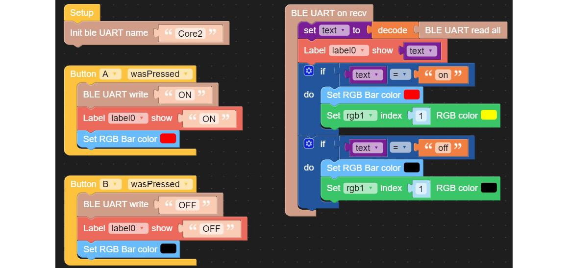
Figure 7.6: UiFlow BLE IoT application device
Note
The Green rgb1 block requires the use of the RGB LED unit. You should add the RGB unit to see the coding blocks.
Notice that the BLE IoT application has alignment with the UiFlow coding process previously discussed.
Quiz 2
In reviewing Figure 7.6’s Blockly code blocks, upon pressing the B button, what information is sent by the UART?
Figure 7.7 shows the BLE IoT application alignment with the UiFlow coding process. As highlighted with callouts, you can rapidly develop a BLE IoT-based application using the UiFlow Blockly code software. In the next section, you will complete the build of the BLE IoT application device and test it using the Nordic Semiconductor nRF toolbox:
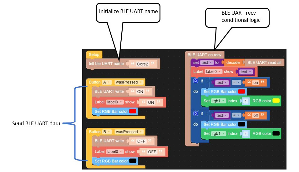
Figure 7.7: UiFlow coding process – BLE IoT application alignment
Congratulations on building the core UiFlow BLE IoT application!
Detecting an M5Stack Core Bluetooth signal with the Nordic Semiconductor nRF toolbox
The Blockly code application built aligns with the UiFlow BLE-UART development process discussed in the previous section. The next step in evolving this BLE IoT application is the use of a tool that will allow an investigation into sending wireless control commands and text messages on mobile devices such as a smartphone or a tablet. The Nordic Semiconductor nRF application is a toolbox that provides a wide range of popular BLE accessories and profiles.
Further, the Nordic Semiconductor nRF application profiles demonstrations of various profiles for health monitoring. Some nRF BLE profiles include Heart Rate, Blood Pressure, and Proximity monitors. These BLE monitors allow developers to explore UI/user experience (UX) designs and data aggregation methods. Such monitoring applications could be explored using the M5Stack Core2 as a human-computer interaction (HCI) development tool. The Nordic UART allows the development of text message and wireless control applications with the ESP32-based controller. Figure 7.8 illustrates some of the UI-based BLE profiles of the Nordic Semiconductor nRF Toolbox app:
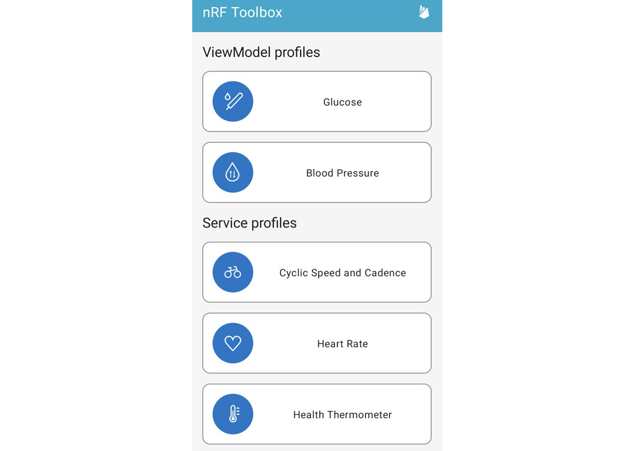
Figure 7.8: Example Nordic Semiconductor nRF Toolbox app profiles
The profile you will explore in this chapter will be the Nordic UART utility service app, shown next:

Figure 7.9: The Nordic UART utility service profile app
Note
The Nordic nRF Toolbox app is available for both Android and iOS mobile devices. Install the app and turn on Bluetooth prior to performing the following steps.
Before starting the Nordic UART utility service profile app, the M5Stack Core2 UI screen needs to be designed. Your UI screen can be designed as shown in Figure 7.10. You may customize the fonts and background screen to meet your visual needs. Further, the message may be changed to suit a more appealing ready prompt.
Quiz 3
Using Figure 7.7, the Nordic nRF Toolbox utility service app is associated with which UIFlow coding process?

Figure 7.10: M5Stack Core2 UI layout
With the UI screen built, click the RUN button on the UiFLow Blockly code editor to execute the software shown in Figure 7.7 on the M5Stack Core2 device. You should see the following text displayed on the M5Stack Core2 Thin Film Transistor (TFT) LCD:

Figure 7.11: M5Stack Core2 UI layout
You can open the UART utility service app from the installed Nordic nRF Toolbox software. Tap on the UART icon to see scanned BLE devices in your environment. Select the Core2-connected device from the list. Figure 7.12 illustrates the scanned connected BLE devices:

Figure 7.12: List of connected BLE devices
Note
The display may vary between an Android and iOS device.
Touching the Core2 listed device shown in Figure 7.12 will display an output window, shown next:
Note
A universally unique identifier or UUID is a 128-bit label used for information in computer systems. Apple Computer in the 1980s originally used UUIDs in its Network Computing System (NCS).
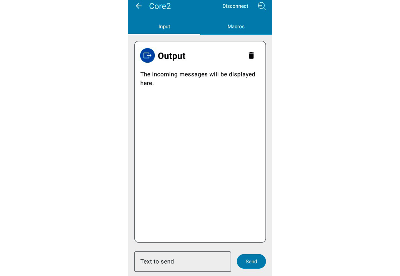
Figure 7.13: Nordic nRF Toolbox UART output window
Note
For iPhone users, select Log to see the Core2 device for selection and Bluetooth pairing with the nRF Toolbox app.
You will type in the text to send from the Nordic nRF Toolbox app to the M5Stack Core2 device, as shown in Figure 7.14. Touch the Send button on the app’s UI to deliver a text message to the M5Stack Core2:

Figure 7.14: Sending Hello World text message to the M5Stack Core2 device
After pressing the Send button, a Hello World text message will be displayed on the output window and the M5Stack Core2 device. Figure 7.15 illustrates a Hello World text message displayed on a smartphone and an M5Stack Core2 device:
Interactive quiz 1
Can low-level emojis such as :) be displayed on an M5Stack Core2 device?
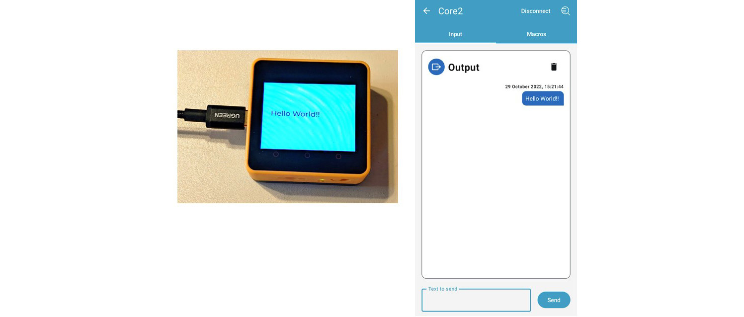
Figure 7.15: Hello World text message displayed on a smartphone and an M5Stack Core2 device
Congratulations on having the Nordic Semiconductor nRF Toolbox running successfully on your smartphone! You can install the Toolbox app on a tablet to achieve the same results. In the next topic of this chapter, you will explore the Blockly code blocks shown in Figure 7.7 by enhancing the Bluetooth messenger’s operation.
Building an M5Stack Bluetooth messenger device
You now have a working knowledge of using the Nordic Semiconductor nRF Toolbox app by setting up the app on a mobile device such as a smartphone or tablet. With the toolbox running effectively on your selected mobile device, you were able to detect and pair with the toolbox. The detection and pairing process was quite seamless, and as shown in Figure 7.13, you were able to send a text message to the M5Stack Core2. Figure 7.16 provides a use-case diagram of the M5Stack Core2 as a basic Bluetooth messenger device:

Figure 7.16: M5Stack Core2 use case – a basic messenger device
As observed in Figure 7.16, the user or actor initiates the messaging by entering or typing an ON message into the UART utility service profile of the Toolbox app. The message is sent or transmitted to the other actor by the M5Stack Core2 to the smartphone or tablet receiving the text. This send-and-receive process is the primary operation of the UART, as discussed in the UiFlow BLE coding blocks pallet overview section of this chapter.
In reviewing the Blockly code blocks in Figure 7.7, the transmit and receive approach of text messaging is quite simple. The BLE UART on recv loop’s first Blockly code block decodes all Bluetooth messages sent by the M5Stack Core2 in a text format. The location of the received text message is captured by the label0 UI. The restriction of the text messages received by the smartphone or tablet is based on the text variable being specific to the on or off hardcoded string messages within the Blockly code blocks’ programming structure. Figure 7.17 illustrates the BLE UART on recv Blockly code blocks’ programming structure. The primary structure of the Blockly code blocks is based on two conditional statements that act as message aggregators to detect specific or hardcoded text sent by the M5Stack Core2 device. With such a programming structure, any text message can be received by a smartphone or tablet quite easily:
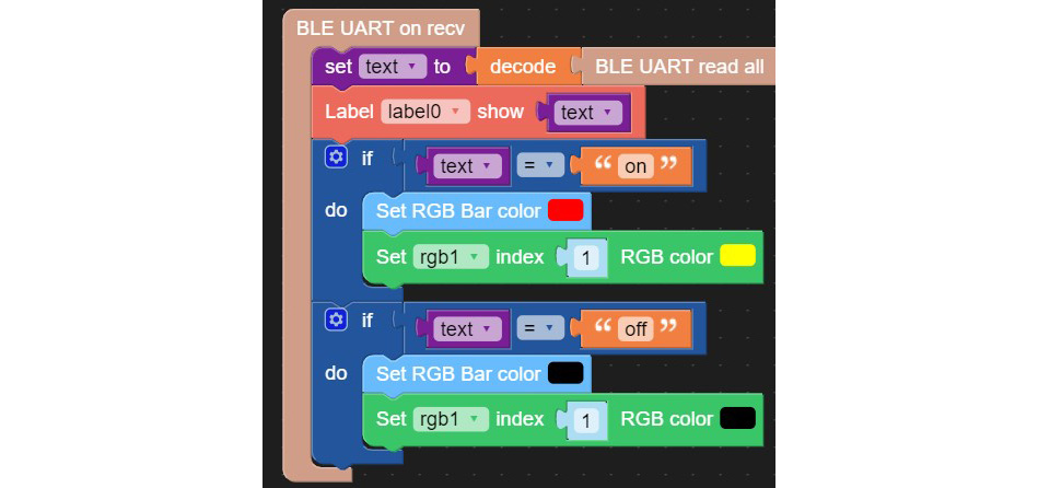
Figure 7.17: BLE UART on recv programming structure
Quiz 4
Identify the Blockly code blocks in Figure 7.17 used to detect the hardcoded text message sent by the smartphone to the M5Stack Core2.
The Blockly code blocks responsible for sending text messages to a smartphone or tablet are shown in Figure 7.18. By touching the first circle (Button A) on the M5Stack Core2 TFT LCD, the text message Mr. Tony Stark will be transmitted to the smartphone or tablet. Touching the second circle (Button B), the text message Mr. Tony Stark is Iron Man will be wirelessly sent to the smartphone or tablet. Figure 7.19 illustrates the event-based outputs associated with M5Stack Core2 Button A and Button B:
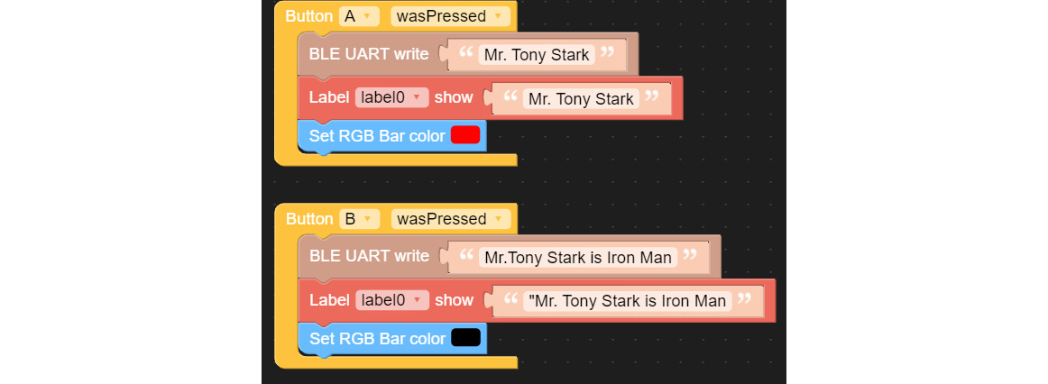
Figure 7.18: Transmitting Blockly code blocks
The BLE UART write Blockly code block allows a string or hardcoded text to be transmitted to a smartphone or tablet. Further, the RGB bar LEDs provide visual indicators of when the message has been transmitted. Although the selected colors used in this text messaging event have no significant meaning, for crucial or real-time operations, the appropriate color would be selected. The selected color would align with the critical messaging of the text—for example, red would align with an emergency status message such as help or stop:

Figure 7.19: BLE UART write transmitted string messages
As observed on your smartphone or tablet, the text messages have been sent and displayed on the Nordic Semiconductor nRF Toolbox app’s output window. Another visual effect occurred, and that is the RGB bar is active during the text message transmitting events. Upon sending the Mr.Tony Stark text message, the red LED of the RGB bar is illuminated. Sending the Mr.Tony Stark is Iron Man text message turns off the RGB bar. These LED illumination effects are shown in Figure 7.19. Therefore, you can send a variety of text messages by changing the string contained within the BLE UART write Blockly code block. Congratulations on successfully building your M5Stack Core2 messenger device! By completing this project, you now have the knowledge and skills to send text messages from the M5Stack Core2 to a smartphone or tablet. With these technical competencies, you will be able to build an M5Stack Bluetooth receiver controller.
Building an M5Stack Bluetooth receiver controller
The M5Stack Core2 Bluetooth receiver controller is an enhancement of the messenger device you build in the previous project activity. The concept of sending a text message using the M5Stack Core2 to a smartphone or tablet was investigated. You will take the prototype built with the use-case diagram shown in Figure 7.16 and convert it to receiver-controller concept diagrams shown in Figures 7.20 and 7.21. Figure 7.20 illustrates an ON-control message controller:

Figure 7.20: Sending an ON-control message
An OFF-control message controller use-case diagram is shown in Figure 7.21:

Figure 7.21: Sending an OFF-control message
Upon the user sending the control message (ON or OFF), the smartphone will display it on its touchscreen LCD. The M5Stack Core2 will display the message and turn the RGB LED bar on or off accordingly. The buttons on the M5Stack Core2 will be used to send ON- or OFF-control messages. Figure 7.22 illustrates the Blockly code blocks to accomplish the wireless control operation:
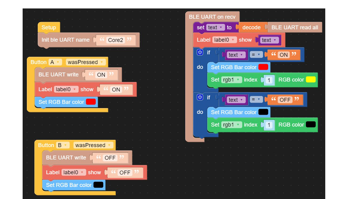
Figure 7.22: BLE-UART receiver-controller Blockly code blocks
Attach the M5Stack Core2 device to your development system using a USB-C cable. Select the correct COM port using the UiFlow software Setup feature. Click the RUN button with your mouse located on the bottom right of the UiFlow Blockly code block editor. Typing ON in the Nordic Semiconductor nRF toolbox text-to-send box and tapping the Send button will display the message on the smartphone or tablet. An ON text message will be displayed on the M5Stack Core2 device, with the red LED bar visible on each side of the BLE UART-based controller. Figure 7.23 illustrates this text-received red LED bar ON operation:
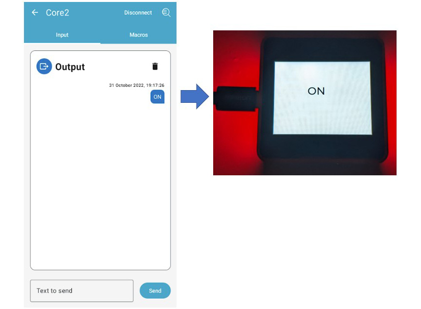
Figure 7.23: Text received red LED bar ON-control operation
Typing OFF in the Nordic Semiconductor nRF toolbox text-to-send box and tapping the Send button will display a message on a smartphone or tablet. An OFF text message will be displayed on the M5Stack Core2 device, with the red LED bar turned on each side of the BLE UART-based controller. Figure 7.24 illustrates this text-received red LED bar OFF operation:
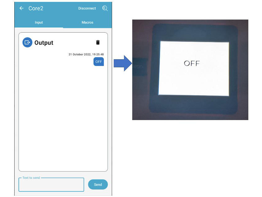
Figure 7.24: The text red LED bar OFF-control operation
If you were able to achieve the outcome results illustrated in Figures 7.23 and 7.24, congratulations on successfully building an M5Stack Bluetooth receiver controller! If your controller did not work successfully, review your Blockly code blocks for errors. With the errors corrected, repeat the steps of the wireless control shown in Figures 7.23 and 7.24 to obtain the correct operation of your Bluetooth receiver controller.
You can enhance the Bluetooth receiver controller by adding a transistor relay module for high-current control operations. The Bluetooth receiver controller can be augmented to drive high-current electromechanical loads such as DC motors and solenoids. The switching contacts of the transistor relay module will be wired to these electromechanical loads operated by the M5Stack Core2 device.
Figure 7.25 shows a wiring diagram to accomplish this augmented control. The electrical wiring between the M5Stack Coe2 and the transistor relay module will require three individual jumper wires to make the electrical interface work properly. You will take three individual jumper wires and place them in line with the standard connector-based wire harness. These individual jumper wires will ensure the control signal voltage produced by the M5Stack Core2 device is present at the transistor relay module to turn it on:
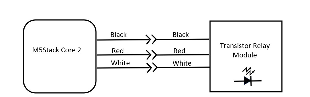
Figure 7.25: M5Stack Core2 to transistor relay module electrical wiring diagram
Figure 7.26 shows the inline jumpers connected to the standard connector-based wire harness:
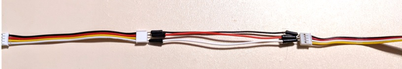
Figure 7.26: The inline jumper wires
You will modify the Bluetooth receiver-controller code to operate the transistor relay module with the M5Stack Core2 device. Figure 7.27 illustrates the modified Blockly code to accomplish the transistor relay control operation. The minor change to the code is the use of the digital write pin blocks. The digital write pin block will turn ON the transistor relay module by writing a binary 1 value to pin 26 of the standard connector-based wire harness. The binary 1 value is equivalent to a DC voltage value of 3.3V. The digital write pin block will turn OFF the transistor relay module by writing a binary 0 value to pin 26 of the standard connector-based wire harness. The binary 0 value is equivalent to a DC voltage value of 0V:
Interactive quiz 2
What effect does typing ON- and OFF-control commands in lowercase letters have on the control operation of the Bluetooth receiver controller?
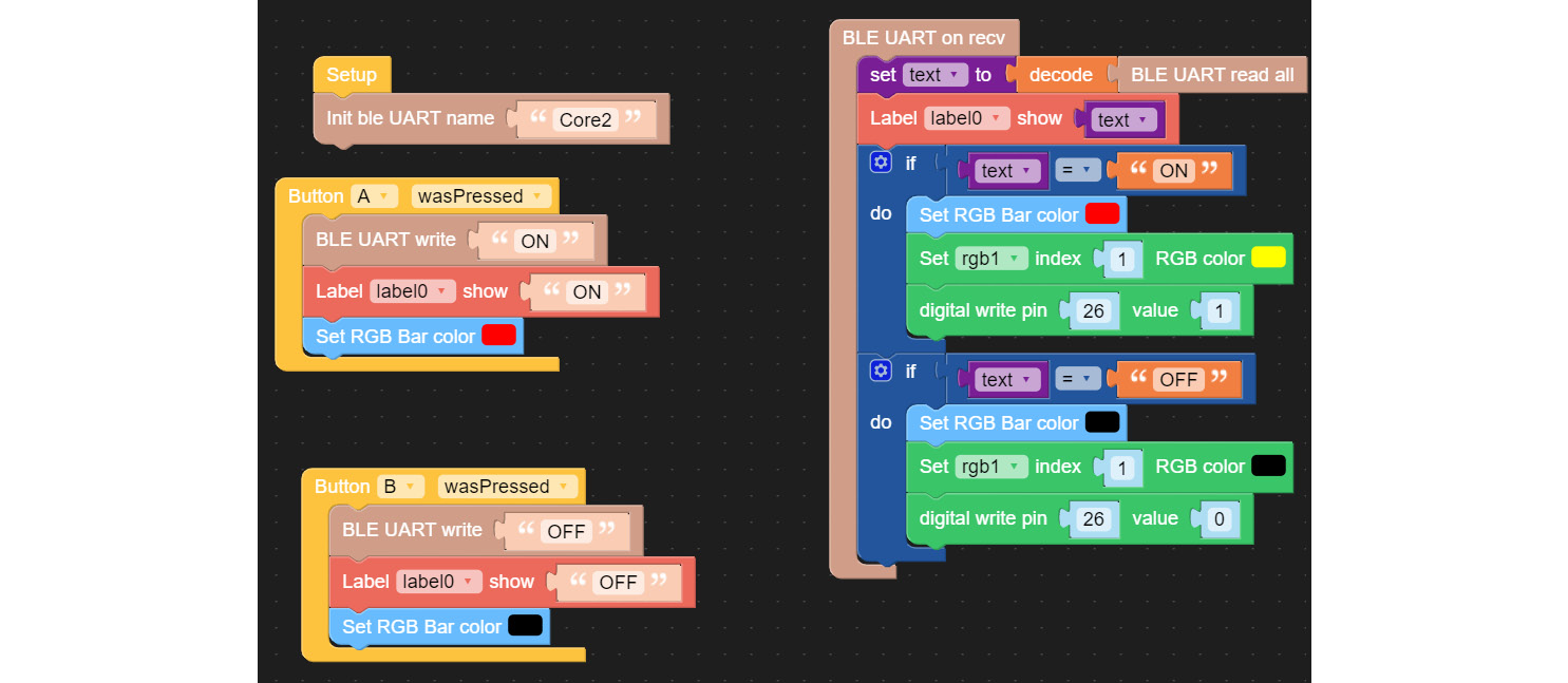
Figure 7.27: The digital write pin Blockly code blocks augment the Bluetooth receiver controller
Attach the modified jumper harness between the M5Stack Core2 device and the transistor relay module. Run the new code on the M5Stack Core2 device within the UiFlow Blockly code editor. Repeat the illustrated step shown in Figure 7.25. The M5Stack Core2 will display ON with the transistor relay module illuminating the red LED. Figure 7.28 illustrates this Bluetooth receiver-controller operation step:
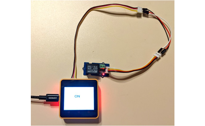
Figure 7.28: The Bluetooth receiver controller in the ON state
Quiz 4
In reviewing the Blockly code shown in Figure 7.27, identify the mystery unit.
Repeating the step illustrated in Figure 7.25 will turn the transistor relay module and the onboard LED off. The M5Stack Core2 device will display an OFF text message during this smartphone or tablet interaction. This operation of the augmented Bluetooth receiver-controller step is illustrated in Figure 7.29:

Figure 7.29: Turning the transistor relay module off
Congratulations on completing the augmented Bluetooth receiver-controller project! You now have the knowledge and hands-on skills to create a wireless controller capable of operating high-current electromechanical such as a DC motor or solenoid. The final project in this chapter is an offshoot of the previous two Bluetooth receiver controllers. This final project will use RGB LED bars with an active piezo buzzer to produce sound. Further, there will be an exploration of creating an electromechanical Morse code key in the last section of this chapter.
Interactive quiz 3
Try using a different control-command text message within the Nordic Semiconductor nRF toolbox, such as a 1 and 0. What effect do these new control-command text messages have on the Bluetooth receiver controller?
Creating a Bluetooth RGB LED light with sound
In the final project of this chapter, the Blockly code used in the previous activity will be used to operate an active piezo buzzer. When you send an ON text message using the Nordic Semiconductor nRF toolbox, the M5Stack Core will turn on the red LED bar, along with blaring an active piezo buzzer. Conversely, sending an OFF text message will turn off the red LED bar and the piezo buzzer. The jumper wire harness provided in Figure 7.26 will be modified by using two wires instead of three. The second standard connector-based jumper is not required for this project. One unique change to the digital output pin 26 is the attachment of a tactile pushbutton switch wired in series with the active piezo buzzer. Figure 7.30 shows an electrical wiring diagram of the tactile pushbutton switch-activated active piezo buzzer circuit:

Figure 7.30: M5Stack Core2 tactile pushbutton switch-activated active piezo buzzer circuit
The concept behind this circuit is to enable the tone of the active piezo buzzer using the Nordic Semiconductor nRF Toolbox app. With the circuit turned ON by the Toolbox app, the tactile pushbutton switch will allow the tone to be heard with a single press. The user, therefore, can turn the ON or OFF tone with a single press of the tactile pushbutton switch. The red RGB LED is not affected by the tactile pushbutton switch due to the optoelectronic emitter being internally hardwired. The final project build prototype is illustrated in Figure 7.31.
Note
An active piezo buzzer uses a common DC voltage to operate the sound-producing electrical component.
The easter egg product with this project is a Morse code oscillator. You can create the dit-dah sounds of a Morse code oscillator by the length of pressing the tactile pushbutton switch. The length of the momentary presses on the tactile pushbutton switch corresponds to the messaging of Morse code. Therefore, with some practice, you will be able to send messages using Morse code. Once you have completed the practice, you can turn it off using the Bluetooth receiver-controller function.
A similar approach may be used with the transistor relay module. The transistor relay contacts will produce a mechanical click sound, thus emulating an old-time Morse code key. The electrical wiring diagram illustrated in Figure 7.25 can be modified by placing the tactile pushbutton switch in line with the white wire. Enabling the electromechanical Morse code device can be accomplished by sending an ON text message with your smartphone or tablet:

Figure 7.31: Bluetooth RGB LED light with sound controller
Figure 7.32 provides an electrical wiring diagram for the mechanical Morse code key:
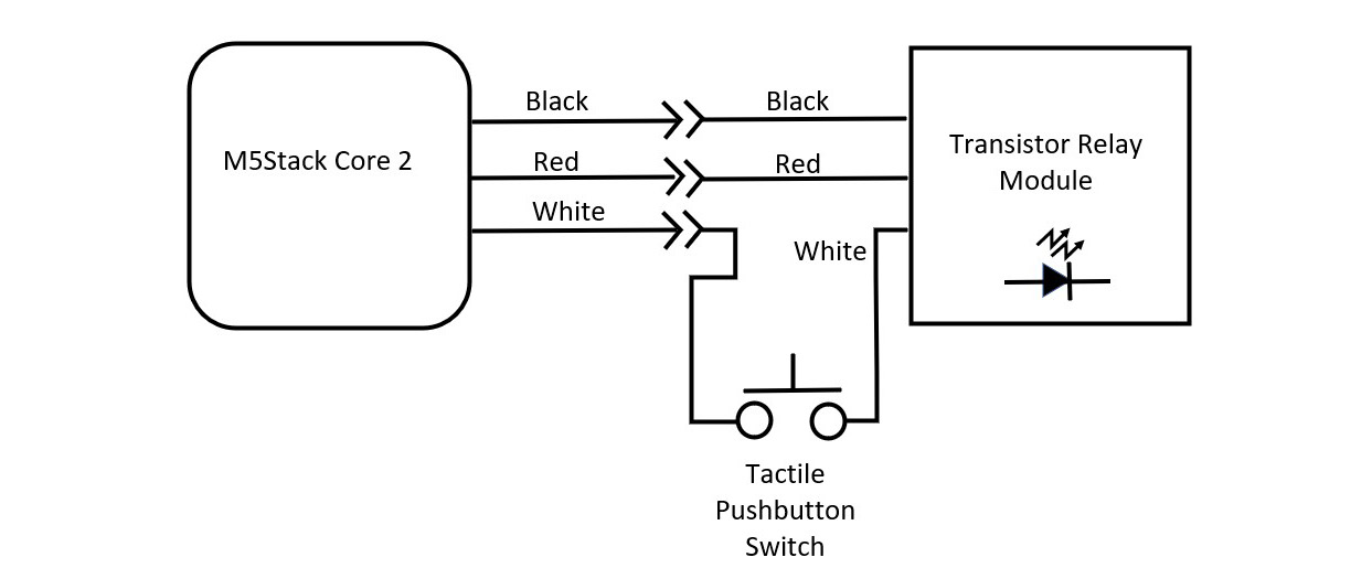
Figure 7.32: Electromechanical Morse code key wiring diagram
The new solderless breadboard prototype for the electromechanical Morse code key is shown in Figure 7.33:

Figure 7.33: Electromechanical Morse code key solderless breadboard prototype
Final congratulations are in order! You have successfully completed creating a Bluetooth RGB light with sound project activities. You now have the technical knowledge and hands-on skills in building Bluetooth devices using an M5Stack Core2 device. Further activities and ideas to consider are to revisit some of the Snap circuits and Arduino Uno projects presented in previous chapters to add a Bluetooth wireless control feature. Expound on the interactive quizzes presented in the chapter to further explore Bluetooth wireless technologies.
Summary
Congratulations—you have completed the hands-on activities and quizzes in this chapter! In the chapter, you learned about the Bluetooth chipset integrated within the ESP32 microcontroller. You learned about the link controller and the baseband subcircuits that aid in the transmission of wireless data. The UiFlow Bluetooth coding blocks pallet was presented in the chapter. You obtained technical knowledge about the operation of a UART through a series of hands-on coding activities implemented on an M5Stack Core2 device. The UIFlow coding process was introduced in this chapter. With the UiFlow coding process, you learned about the BLE IoT application alignment of the key coding steps. The key coding steps learned in this chapter were Initialize BLE UART Name, Send BLE UART Data, and BLE UART recv conditional logic. BLE IoT application Blockly code blocks were introduced and implemented within this chapter. With the BLE IoT application, you were able to use the Nordic Semiconductor nRF toolbox to detect the UUID of the M5Stack Core2 device.
Further, you built a Bluetooth Messenger device using the BLE IoT application blockly code blocks and the Nordic Semiconductor nRF toolbox. With these wireless tools, you were able to send a text message to your smartphone or tablet and the M5Stack Core2 device. You learned how to convert the Bluetooth messenger device into a receiver controller. With the receiver controller, you were able to operate the M5Stack Core2 device RGB LED bar. You augmented the output operation of the controller by wiring a transistor relay module.
Finally, the Bluetooth receiver controller was electrically modified to operate an active piezo buzzer. To provide a silencing feature to an active piezo controller, you wired a tactile pushbutton switch to the control signal line of the M5Stack Core2 device. With the inline tactile pushbutton switch, you were able to create a practice Morse code tone oscillator. You then transformed the practice Morse code tone oscillator into an electromechanical key by wiring a transistor relay module. Pressing the tactile pushbutton switch to turn on and off the transistor relay module produced the mechanical dit-dah sound of a Morse code key.
In the final chapter of M5Stack Electronic Blueprints, you will become familiar with the Wi-Fi features included with M5Stack Core and Core2 devices. You will conduct Wi-Fi experiments to scan and detect wireless nodes. You will explore visual detection indicators and audible alarms in the chapter. You will be introduced to using the Arduino IDE platform to code C/C++ Wi-Fi-enabled detection devices.
Interactive quiz answers
Interactive quiz 1: Yes, based on emojis created using text characters.
Interactive quiz 2: The RGB LED bar will not turn on.
Interactive quiz 3: The Bluetooth receiver controller will not respond. Blockly code will need to be modified to accept the new text commands.
Quiz answers
Quiz 1: Oscillator
Quiz 2: OFF
Quiz 3: Send BLE UART Data and BLE UART recv conditional logic
Quiz 4: RGB unit