
Functional Magnetic Resonance Imaging
Pascal Wallisch
This chapter will introduce you to functional magnetic resonance imaging (fMRI) as a fundamental noninvasive tool in understanding brain functioning in human and non-human primates. We will describe the basic physics behind both structural and functional magnetic resonance imaging. We will then describe the major experimental paradigms used in fMRI research and the kinds of data that are collected in an fMRI experiment. Finally, using existing fMRI data from a visual attention experiment and face recognition study, we will show you how to analyze and visualize the data to come up with a statistical parametric map of activation in the brain. After completing this project, you should expect to understand how researchers take fMRI data to infer activation associated with a behavioral task in different parts of the brain.
Keywords
functional magnetic resonance imaging; blood oxygen level-dependent signal; Lamour frequency; voxels; resels
24.1 Goals of This Chapter
This chapter will introduce you to functional magnetic resonance imaging (fMRI) as a fundamental noninvasive tool in understanding brain functioning in human and non-human primates. We will describe the basic physics behind both structural and functional magnetic resonance imaging. We will then describe the major experimental paradigms used in fMRI research and the kinds of data that are collected in an fMRI experiment. Finally, using existing fMRI data from a visual attention experiment and face recognition study, we will show you how to analyze and visualize the data to come up with a statistical parametric map of activation in the brain. After completing this project, you should expect to understand how researchers take fMRI data to infer activation associated with a behavioral task in different parts of the brain.
24.2 Background
Functional magnetic resonance imaging has emerged as the dominant form of noninvasive functional imaging in humans. Although it is a relatively young technology that began in the early 1990s, it now plays a major role in many subfields of psychology, cognitive science, and neuroscience. It is even creeping up in other disciplines such as sociology and economics. As of the middle of 2013, a PubMed search revealed over 338,055 papers that reference the use of fMRI.
The development of fMRI began more than 70 years ago when Linus Pauling discovered that oxyhemoglobin and deoxyhemoglobin have different magnetic properties (Pauling and Coryell, 1936). He noted that deoxyhemoglobin was paramagnetic. However, it wasn’t until the 1990s that researchers used these properties of hemoglobin to measure what would be later termed the blood oxygen level-dependent (BOLD) signal (Bandettini et al., 1992; Kwong et al., 1992; Ogawa et al., 1992). Since that time, thousands of studies have been completed that have dramatically increased our understanding of the human brain. In 2001, Logothetis and colleagues demonstrated that the BOLD response correlates with local field potentials in monkeys viewing a flickering checkerboard, leading to the conclusion that the BOLD response is a post-synaptic phenomenon (Logothetis et al., 2001). Thus, the BOLD response is a reflection of the post-synaptic response to the local neural activity.
Functional magnetic resonance imaging using BOLD imaging provides a rapid in vivo glance into human brain function. These experiments are fundamentally based on the principle that the brain oversupplies blood and oxygen to regions that increase their activity relative to the state before a stimulus is presented; yet this indirect measurement must be interpreted cautiously and has led to some criticism of the field. Specifically, the term “BOLD response” is not interchangeable with “neural activity.” While the BOLD response is a reflection of the neural activity, it is also dependent on neurovascular coupling including the calcium dynamics in astrocytes and the vasodilation of arterioles. Thus, group differences indicate physiological differences, but they do not necessarily indicate differences in neural activity. Additionally, negative results cannot be interpreted as not having a physiological difference. Finally, BOLD is based on the relative signal between two conditions, usually an experimental state and fixation or two experimental conditions. Since BOLD is relative and indirect, Logothetis and colleagues concluded that fMRI is limited to “conditionally confirm” prior knowledge from other studies (Logothetis et al., 2001). Therefore, inferences of brain function derived from fMRI should draw upon other psychophysical and physiological measurements.
24.2.1 Basic Physics of the MRI Signal
We will describe the basic physical principles that create the MRI signal. Although the physics behind MRI is inherently quantum mechanical, most of the ideas can be expressed in classical terms that you would learn in a high school physics course. There are two phenomena that must be understood: precession and relaxation. Atoms with an odd number of protons (or neutrons) in their nucleus such as hydrogen act like tiny magnetic dipoles because they possess a quantum mechanical spin. As you may remember from your high school physics, an electrical charge that is rotating will generate a magnetic field perpendicular to its rotational plane according to the right-hand rule. In the presence of an external magnetic field, Bo, these proton magnetic dipoles will tend to align with it by precessing around the Bo axis like a top precesses about the gravitational field. The precession frequency, Fo, of the protons in the nucleus is proportional to the strength of Bo with a proportionality constant that depends on the type of atomic nucleus:
![]() (24.1)
(24.1)
This is called the Lamour frequency, and it characterizes the resonant frequency of the atomic material that is being imaged. In the presence of the static magnetic field, Bo, the spinning protons will eventually settle and align their spins with the external magnetic field and by doing so will create their own internal magnetization, Mo. The time constant that characterizes this settling or relaxation time is called the T1 time.
To create an MRI signal, an external oscillating magnetic pulse, B1, is applied in the transverse direction perpendicular to Bo. This pulse is called an RF pulse because the magnetic field frequency is in the radio frequency range (i.e., megahertz range) and typically lasts for a millisecond or so. This pulse is generated by a wire coil that lies in a plane parallel to Bo. If the oscillating frequency of B1 is close to the resonant frequency (i.e., the precession frequency of the protons), the internal magnetization will be perturbed and shift its orientation toward the transverse direction. This is very much like a forced harmonic oscillator that will begin to oscillate with a very large amplitude if a forcing frequency matches the resonant frequency. The shifted internal magnetization of the protons will precess at its resonant frequency, and will inductively generate an electrical signal in the same coil that generated the RF pulse. Again from high school physics, you know that a changing magnetic field generates an electrical field, and will create an electric current if a wire is nearby. This inductive current will decay in time with a relaxation time constant T2 after the RF pulse is turned off because the precessing protons that initially were in phase with each other will no longer be phase locked with each other. The time between pulses is referred to as the repetition time, TR.
To create an image from the MRI signal, additional gradient coils create a gradient in the static magnetic field, Bo, such that the strength of the static field varies linearly along different spatial axes. According to the Lamour frequency equation, the resonant frequency is proportional to the magnitude of the static field. In one dimension, a gradient will shift the resonant frequency of the atomic material. If an RF pulse is applied at a particular frequency, this will predominantly excite only one point along the spatial dimension. Imagine a set of harmonic oscillators with linearly varying resonant frequencies placed along one axis. A forcing oscillation at a particular frequency (the RF pulse in MRI) will excite those harmonic oscillators whose resonant frequencies are close to the forcing frequency. More importantly, the relative phase between the oscillator and the forcing oscillation will vary linearly along the axis. This is the essence of MRI imaging.
24.2.2 BOLD Signal (fMRI)
We will now describe the basic principles of the blood oxygen level-dependent (BOLD) signal. The oxygenation concentration of blood was discovered to alter the MRI signal (Ogawa et al., 1992). In particular, as the ratio of oxygenated to deoxygenated hemoglobin increased, the MRI signal increased. It was soon found that brain activation in the human also affected the MRI signal, presumably due to changes in blood oxygenation levels surrounding the brain tissue (Kwong et al., 1992). The time course of the BOLD signal initially shows a weak decrease, due to a relative increase in deoxyhemoglobin concentration associated with increased oxygen utilization, followed by a much stronger increase, due to relative decrease in deoxyhemoglobin concentration associated with the oversupply of oxygenated blood without a change in oxygen utilization, that peaks several seconds (~5 seconds) after a stimulus is presented to the subject. The mismatch between supply and utilization is critical to the BOLD phenomenon (Raichle and Mintun, 2006). Vascular physiology suggests that the source of this BOLD signal is primarily the venous and capillary blood as opposed to arterial blood and more specifically the dynamic relationship between cerebral blood flow, cerebral blood volume, and the cerebral metabolic rate of oxygen or oxygen utilization. Most studies have focused on the later, robust increase in the MRI signal. You should keep the relatively slow dynamics of the signal in mind when interpreting fMRI data because this places a limit to the temporal resolution of tracking neural activity and the ability to separate neural events close in time.
Functional magnetic resonance imaging initially began by simply subtracting the mean value of two states akin to computing the correlation between a simple box car function and the data; however, more recent studies use more complex modeling methods by incorporating knowledge of the hemodynamic response to identify active regions (Friston et al., 1995; Worsley and Friston, 1995). The hemodynamic response is the shape and amplitude of the BOLD signal in response to a stimulus. As the stimulus approaches an instantaneous impulse, the response becomes the hemodynamic response function (HRF). This is used in the convolution with the stimulus to create knowledge of the predicted BOLD response, which is then used to identify regions that are active. Initial studies of the HRF were completed in visual cortex in the mid-1990s (Boynton et al., 1996). More recently, the hemodynamic response has been shown to be variable across participants, regions, and trials due to the timing of neural activity and differences in neurovascular coupling (Aguirre et al., 1998; Handwerker et al., 2004; Steffener et al., 2010). To account for more of the variability, researchers have begun using the temporal and dispersion derivatives of the HRF (Calhoun et al., 2004; Steffener et al., 2010). In 2001, Henson and colleagues statistically demonstrated that the inclusion of these terms accounted for most of the variance in the hemodynamic response (Henson et al., 2001).
24.2.3 Preprocessing of the BOLD Signal
We will describe the data structure and the basic preprocessing steps for functional magnetic resonance data. The data that are acquired in a functional magnetic resonance imaging (fMRI) experiment require a number of preprocessing steps before formal statistical data analyses can be performed. The data we will give you, available on the companion web site (courtesy of Christian Buechel, Karl Friston, and Rik Henson), have already been preprocessed. However, it is helpful to understand what has been done to the data before you work with it (Smith, 2003a, b).
Functional magnetic resonance imaging consists of a series of whole brain images that are usually collected at uniform intervals typically between 1–5 seconds. Each whole brain volume is made up of a series of 2D brain slices, although newer structural imaging is collected in 3D rather than as a series of 2D slices. The signal is initially represented in the Fourier domain as a set of complex numbers at different frequencies and phases (k-space representation). This needs to be transformed into a set of real numbers in the time domain using a 2D Fourier transformation for each slice and each time point. The output of the Fourier transformation is an image for each slice in a proprietary format of the company that produced the scanner. The Fourier transforms allow the data to be viewed as shown in Figure 24.1. For illustrative purposes, a T1-weighted slice is shown in Figure 24.1 (top left). Each 2D slice is made up of many subunits known as voxels, or discrete volume elements (Figure 24.1, top right). The middle image in Figure 24.1 shows a zoomed view of the voxels. Each of these voxels is actually a numeric value that can be viewed in color or grayscale as shown in Figure 24.1 (bottom). These images are then collated into whole brain images as either an ANALYZE format file (.img/.hdr pair) or a NIFTI-1 format file (.img/.hdr pair or .nii). The latter is more common with newer software packages. The difference between the image formats is the information stored in the header of the files. One key difference is that NIFTI-1 files now store the origin and rotation of the image, which allows linear transformations to be stored in the image headers.

Figure 24.1 An illustrative example of voxels using a T1-weighted image. Top left: the view of the entire slice. Top right: the view of all subunits known as voxels, or discrete volume elements, within a single slice. Middle: a magnified view of a subset of voxels. Bottom: the numeric value of each voxel.
Once you have collated the data into whole brain images, preprocessing can begin. In fMRI, we are generally analyzing each voxel individually. Each voxel has a 3D location associated with it and is measured across time to produce a time series that can be represented as a 4D matrix. Because each brain volume image is acquired as a series of two-dimensional slices, each slice is acquired at a slightly different time. Therefore, slice-timing correction is performed, although this is less important in block designs. Following slice-time correction, motion correction is then performed such that each whole brain volume is spatially aligned. Because motion and slice acquisition time are interdependent and processes for simultaneously correcting for both do not exist, some have argued that slice-time correction should be applied after motion correction. Importantly, if slice-time correction is performed first, then the motion correction will not require reslicing of the data. Next, data are spatially normalized to an atlas space, typically MNI space for fMRI (Evans et al., 1993), using both affine and non-linear transformations. Following this transformation, the data are resampled to a common grid to produce isotropic voxels that are generally 2 or 3 cubic millimeters in size. Using 2 cubic millimeter voxels will require about 4 times as much disk space as using 3 cubic millimeters. After the data have been resampled, it is spatially smoothed using a Gaussian kernel with a full-width half maximum of 1–2 times the voxel size, typically 8 mm. With the exception of resting state data, temporal filtering is usually included as part of the statistical analysis.
24.2.4 Experimental Designs
We will describe the four major types of experimental design used in fMRI: (1) the block design, (2) the event-related design, (3) the mixed block event-related design, and (4) the resting state design (Donaldson and Buckner, 2003). The block design was the first approach used in early fMRI experiments and is quite easy to implement. Blocks of time (typically tens of seconds long) are defined in which subjects are either presented with multiple stimuli or perform a task repeatedly (experimental block), or are presented with nothing or asked to rest (control block). These blocks are typically presented in an alternating fashion. The BOLD signal is then compared between the experimental and control blocks. Block designs are useful in clinical studies where the main question is where and to what extent a region is activated. In contrast, the event-related design uses a series of short, 0–10 second, rapidly presented stimuli. The event-related design is used when you want to examine the relationship between a behavioral event and the dynamics of the BOLD signal. Additionally, several different stimuli can be used and presented in a pseudo randomized fashion expanding the number of comparisons that can be made from a single study. However, each stimulus condition or experimental manipulation should have at least 30 events (Huettel and McCarthy, 2001). The mixed block event-related design is simply a combination of the block design and event-related designs. Short stimuli are grouped into separate blocks with the idea that the design will elucidate the brain state of the task as well as the responses to individual trials. This is the least commonly utilized design. Finally, the resting state design is the easiest design to implement. Researchers using a resting state design instruct the participant to lie still and either: (1) keep their eyes open; (2) keep their eyes closed; or (3) fixate on a crosshair in the middle of a screen (Biswal et al., 1995; Fox et al., 2005). This type of design is advantageous in clinical studies where patients might not be able to perform behavioral tasks or provide a response to the researcher.
24.2.5 Analysis Methods
We will briefly describe several analysis techniques that are used in fMRI analyses as well as different software packages. In this chapter, we will focus on the general linear model and apply it to each voxel in a mass univariate approach (Friston et al., 1995). The mass univariate approach utilizes the general linear model because of the ease of finding the solution using matrix inversion:
![]() (24.2)
(24.2)
Y is a column vector and represents the fMRI time series data from a single voxel with N data points. X is an N×M matrix representing the predicted brain responses to the experimental stimulus and is formed by convolving each condition in the experimental design with the hemodynamic response function. M is the number of experimental conditions. β is a column vector of the unknown amplitudes of the BOLD response for each condition that is being estimated by the model and ε is normally distributed noise. The solution to the general linear model is:
![]() (24.3)
(24.3)
where X’ is the transpose of X. Inferences are then based on whether β is significantly greater than or less than 0 or different between two conditions.
While the examples in this chapter use the mass univariate approach, it is useful to know about other approaches. One commonly utilized approach is independent component analysis (ICA; Calhoun et al., 2001). Two advantages of ICA are that it: (1) does not require an a priori model of the expected BOLD response; and (2) does not suffer from the multiple-comparisons problem of mass univariate analyses. Another approach is partial least squares (PLS; McIntosh et al., 1996). The advantage of PLS is that it is a multivariate technique that can separate the effects of different conditions. Additionally, it also does not suffer from the multiple-comparisons problem.
An alternative to investigating evoked brain activity is to investigate brain connectivity during different tasks. Two main methods have been developed and used for this purpose. The first is psychophysiological interactions (PPI), which investigate whether the connectivity between two brain regions is modulated by the experimental condition (Friston et al., 1997; Gitelman et al., 2003; McLaren et al., 2012). PPI analyses are implemented using the general linear model with additional predictors that are added to X. Another approach that has been developed is called dynamic causal models (DCM), which investigates how connectivity between brain regions is modulated by experimental contexts using generative models that better capture the dynamic and nonlinear nature of the signal (Friston et al., 2003).
Finally, it is useful to know that there are several free programs, in addition to MATLAB for neuroimaging, that include: (1) Statistical Parametric Mapping 8 (SPM8; Wellcome Department of Imaging Neuroscience, University College London, UK; http://www.fil.ion.ucl.ac.uk/spm/) is written for MATLAB; (2) FMRIB Software Library (FSL; Functional MRI of the Brain Centre, University of Oxford, UK; http://www.fmrib.ox.ac.uk/fsl/); (3) Analysis for Functional NeuroImages (AFNI; Medical College of Wisconsin, USA; http://afni.nimh.nih.gov/afni/); (4) CARET (Washington University School of Medicine, USA; http://brainvis.wustl.edu/wiki/index.php/Caret:About); and (5) Freesurfer (Athinoula A. Martinos Center for Biomedical Imaging, Massachusetts General Hospital, USA; http://surfer.nmr.mgh.harvard.edu/). Often times, studies involving more advanced methodology will utilize components from each of these programs. Additionally, each of these programs provides an email list for imaging questions and technical support.
24.2.6 Multiple Comparisons
We will briefly describe several ways to correct for the problem of multiple comparisons. As mentioned previously, this chapter focuses on the mass univariate analysis of neuroimaging data, which can involve over 100,000 statistical tests. Applying a Bonferroni correction to the data is too conservative to find significant effects. Thus, several other methods have been developed and/or applied to neuroimaging data.
The first method is called the family-wise error (FWE) correction. Instead of correcting for the number of voxels, the FWE correction is a correction for the number of independent tests, or resels (resolution elements). The number of resels in an image is a function of the number of voxels and the spatial correlation as measured in full-width at half-maximum (FWHM). From the number of resels, one can compute the statistic required to achieve an expected Euler characteristic of 0 or 1. This will be the height threshold to determine if a voxel is significant or not.
The second method is called the false discovery rate (FDR) correction. The FDR correction leads to the inference that less than q of the significant voxels are false positives. Briefly, after sorting the p-values (P) from smallest to largest, find the largest k that satisfies the following equation:
![]() (24.4)
(24.4)
where m is the number of voxels and C(m) is a constant describing the relationship between voxels. If the voxels are independent or positively correlated, then C(m)=1; otherwise:
![]() (24.5)
(24.5)
All voxels with a p-value less than P(k) are significant at an FDR of less than q(Genovese et al., 2002). As with FWE, this is a voxel-wise correction. Recent work has implemented FDR at the cluster level (Chumbley and Friston, 2009).
The third method uses both a voxel-wise threshold and an extent threshold. This correction leads to the inference that a cluster is significant, which is fundamentally different from the first two methods that usually correct the data at the voxel level. To find the extent of a cluster, a Monte Carlo simulation needs to be performed (Forman et al., 1995). One program that will perform the simulation is 3dClustSim (AFNI; Cox, 1996). The cluster extent is based on the voxel threshold, the smoothness of the image, and the spatial distribution of voxels being investigated. One caveat of using this method is that one should be cognizant of using a higher voxel threshold in a smaller cluster compared to using a lower voxel threshold in a larger cluster.
Multiple-comparison correction procedures that correct inferences at the voxel level penalize studies that have higher number of voxels. As the number of voxels increases, the number of individuals in the study needs to increase to detect the same area. While there are several possible solutions, all of them have their drawbacks. Decreasing the resolution of the image will result in fewer voxels and, assuming the statistics are the same, potentially reveal more regions that are truly significant. As the voxel size increases, the ability to detect an effect will be decreased. Given that functional changes are likely to occur in only parts of any anatomical region, the cluster size must be significantly smaller than the region. Thus, as imaging improves more robust results will be needed to reduce the cluster extent threshold. An alternative to voxel-wise procedures is multivariate approaches (e.g., ICA and PLS).
24.2.7 Caveats and Limitations
We will briefly describe several of the caveats and limitations of imaging. First, the small sample sizes and low trial numbers used in fMRI studies typically result in lower power. Thus, negative results cannot be interpreted as the absence of the effect of interest. Rather, interpretation should be focused on the positive findings. Furthermore, group comparisons rely on the assumption that neurovascular coupling is the same across all participants and groups. If the neurovascular coupling changes, then the hemodynamic response function used in the analysis will not be correct. However, the goal of most studies is to show differences in the neural correlates, which encompass neurovascular coupling differences. Second, the interpretation of the data is only as good as the cognitive construct or theory that is being tested. If the manipulation does not test the theory or test it properly, then the interpretation will also be invalid. Thus, researchers should make sure the cognitive construct is valid and that the experiment is manipulating the cognitive theory of interest, before conducting the imaging portion of the study. Finally, in terms of the analysis, the most critical thing is the proper model. Functional MRI suffers from its own hemodynamic inverse problem. Specifically, neural activity is linearly related to the hemodynamic response, but we use the hemodynamic response to infer neural activity by specifying the onset and duration of the expected neural activity (Buckner, 2003). However, neither of these parameters are known and must be estimated from the task design. For example, in a visual search task, the stimulus may be present for 5 seconds, but the individual finds the target after 2 seconds. The neural activity in some regions may have only lasted 2 seconds and this timing needs to be taken into account in the model (Shulman et al., 2003). Thus, it is critical to know when the neurons increase and decrease firing during your task and not simply when the stimulus comes on and goes off. Despite the caveats and limitations, fMRI is a very powerful non-invasive tool for understanding brain function.
24.3 Exercises
These exercises are presented to introduce some of the techniques used to analyze fMRI data. Before you begin, you will need to download SPM8 (http://www.fil.ion.ucl.ac.uk/spm/software/) and the scripts available on the companion site (M-files directory) and then add them to your matlab path using addpath and genpath:
The example data are from two studies: (1) an experiment involving visual motion from one human subject (data courtesy of Karl Friston and Christian Buchel at the Functional Imaging Laboratory at University College London; Buchel and Friston, 1997); and (2) an experiment involving the repeated presentations of famous and non-famous faces from one human subject (data courtesy of Rik Henson at the Wellcome Department of Cognitive Neurology, University College London; Henson et al., 2002) and are available on the companion web site.
The first example dataset uses a block design (attention folder) with four conditions: viewing of stationary dots, attending to moving dots, viewing moving dots with no attention, and viewing a fixation crosshair. A complete image of the brain was acquired every 3.22 s (i.e., TR=3.22 seconds) and there are 360 time samples for the whole experiment. The data are stored in image files (*.img) and a timing file (multi_condition.mat). Often times imaging data are stored in a series of 3D images that are hard to manipulate in MATLAB, so conversion to a 4D file is helpful. To concatenate the 3D images in the example data set, type concatimages(’fMRIdata.nii’, ’snff*img’). To load the images, type img=openIMG(’fMRIdata.nii’). The variable img is a four-dimensional matrix corresponding to the x (medial-lateral; sagittal plane), y (anterior-posterior; coronal plane), z (inferior-superior; axial plane) spatial dimensions and time. Each element of the variable img represents the BOLD signal from one voxel or volume element from the brain at one time point. One way researchers examine activation at a particular voxel is to cross-correlate the signal with the expected hemodynamic response. Begin with a simple boxcar hemodynamic response that is on (i.e., 1) during the active blocks (stationary dots, moving dots without attention, and attending to moving dots) and off (i.e., 0) during the control blocks (e.g., when the subject is viewing a fixation crosshair). The experiment begins with a rest (control) block of 10 TRs:
hemo=[repmat([repmat(0,10,1);repmat(1,10,1);repmat(0,10,1);repmat(1,10,1);repmat(0,10,1);repmat(1,10,1);repmat(0,10,1);repmat(1,10,1);repmat(1,10,1)],4,1)];
Begin by looking at one voxel. Plot img(31,6,25,:) along with the expected hemodynamic response in two subplots of the same figure using the subplot function. You will first need to use the reshape function to convert img(31,6,25,:) into a column vector using voxel=reshape(img(31,6,25,:), 360, 1). Adjust the y-axis of the hemodynamic plot to range from −0.2 to 1.2 using the axis function. The result should look like Figure 24.2.

Figure 24.2 The BOLD signal from one sample voxel (top) along with the expected hemodynamic response (bottom).
Notice how the BOLD signal oscillates at the same frequency as the expected hemodynamic response.
Exercise 24.2
Compute the cross-covariance between the voxel activation and the expected hemodynamic response using xcov:
The result is shown in Figure 24.3 (top panel).

Figure 24.3 The cross-covariance between the sample voxel and the expected hemodynamic response at a broad time scale (top) and a narrow time scale (bottom).
The xcov function generates the cross-covariance instead of the cross-correlation because you want to examine how the two signals covary with respect to their respective means. The function xcorr would consider their covariation ignoring their mean values despite the fact the two signals have completely different units and magnitudes. The ’coeff’ flag makes sure that the output represents the normalized correlation coefficient ranging from −1 to 1. If you zoom in the figure (Figure 24.3, bottom panel), you will notice that the peak in the cross-covariance occurs at a lag time of 2. This is the biophysical delay between the performance-based neural activation and the hemodynamic response.
To quantitatively determine which voxels are significantly activated, you will apply a regression model or general linear model (GLM) to find a linear relationship between the expected hemodynamic response and the actual BOLD signals. Specifically, you will find the optimal (in the least-squares sense) offset and gain parameters that relate the expected hemodynamic response and the voxel’s BOLD signal such that
![]() (24.6)
(24.6)
where ε is normally distributed noise. However, before computing the parameters, you need to introduce the biophysical delay into the expected hemodynamic response using spm_hrf and conv.
Exercise 24.3
Run statistics on the sample voxel using the canonical hemodynamic response. What are the constant/offset and gain parameters that are computed and their p-values?
B(1) is the constant/offset and B(2) is the gain parameter relating to the active blocks.
T-statistics and their associated p-values are based on contrasts. In this example, the contrast (λ) for the offset, the first parameter, is [1; 0] since we want to test if the offset is greater than 0 and the contrast for the gain, the second parameter, is [0; 1] since we want to test if the gain is greater than 0. The equation for generating the T-statistic is:
![]() (24.7)
(24.7)
where λ is the contrast and X is the predictors. σ2 is residual sums of squares (ResSS) divided by the degrees of freedom in the model.
Exercise 24.5
Run spm_firstlevel on the entire dataset. The M-file spm_firstlevel does the same computations as in the previous exercise. The input is a structure variable or a mat-file containing a structure variable described below. What are the constant and gain parameters that are computed and their t-statistics?
The names of the three conditions are: NoAtten, Attention, and Stationary. Here is an example of the Contrasts field structure. Make this for all 26 combinations of conditions including compared against fixation (use ’none’).
>>SPMin.Contrasts(1).left={’NoAtten’};
>>SPMin.Contrasts(1).right={’Attention’};
>>SPMin.Contrasts(1).STAT=’T’;
In the M-files directory, the file Allfields_firstlevel.mat has an example structure with all fields. Additionally, AllContrasts_firstlevel.mat has an example structure identical to above, but with all 26 contrasts included. Definitions of each of the fields can be found in the help for spm_firstlevel.
In the file selection window, change the file filter from .* to fMRIdata.*. Then select all entries with the filename fMRIdata.nii. Now view the design matrix.
The design matrix should look like Figure 24.4.
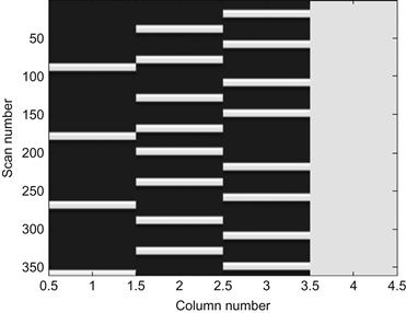
Figure 24.4 The design matrix for the general linear model. The first three columns are the expected hemodynamic responses for the three conditions: stationary dots, moving dots without attention, and attending to moving dots. The fourth column is the constant/offset. Each row represents one fMRI volume.
The beta_*img stores the gain parameters for each condition, and the constant/offset parameter. There will be one image for each column of the design matrix. The con_*img stores the difference in or averages of the gain parameters and/or averages across runs. The spmT_*img stores the t-statistics for each contrast. These images can be found in the results directory (e.g., attention/results) and opened with openIMG:
Exercise 24.7
Use slover to overlay the significant clusters from the contrast of moving dots without attention versus attending to moving dots on every other axial slice.
In the image selection window, select single_subj_T1.nii, which can be found in the canonical folder inside the spm8 directory and then select spmT_NoAtten_minus_Attention_peaks_<date>_thresh3.113_extent10.nii from the results directory. Click Done. Next, specify the single_subj_T1.nii as a *Structural image and the spmT image as a Blobs. Set the Colormap to gray. Set the range to 0.5 4. Since the input image was thresholded at p<0.001, the voxels being viewed will exceed that threshold. Click Axial. Set the slices to be 0:2:30 representing Z=0 to Z=30. The resulting figure should look like Figure 24.5.

24.4 Project
This project involves analyzing the second example fMRI dataset (repetition folder) from an experiment involving the repeated presentations of famous and non-famous faces using the general linear model and then inspecting the results. The pre-processed images follow the filename structure swr*img and the timings file is all-conditions.mat. Specifically, you should do the following:
Apply the spm_firstlevel function to determine significant activation due to the task as in Exercise 18.4.
Use a p-value of 0.001 for the threshold for activation and a cluster extent of 20 using peak_nii as in Exercise 24.5 to determine significant areas.
Generate a grayscale plot for every other x-y slice of the brain (Z=−60 to Z=80) for the contrast famous faces greater than non-famous faces (F1+F2−N1−N2) using slover. Your result should look like Figure 24.6.

Figure 24.6 Axial slices from the contrast famous faces greater than non-famous faces at p<0.001 in at least 20 contiguous voxels overlaid onto a T1-weighted image from a single subject. White represents significant activation. Numbers are the slice plane in millimeters from the origin. Negative numbers indicate the slice is inferior to the origin.
24.4.1 Methods Used to Collect fMRI Data
For the repetition fMRI dataset, the paradigm is a 2×2 factorial event-related design. Twenty-six famous and 26 non-famous grayscale faces were each presented twice for 500 ms. An oval checkerboard was present throughout the interstimulus interval and is the implicit baseline in the analysis. Stimulus onset asynchrony (SOA) was at least 4.5 s and null events were randomly intermixed to increase the variability in the timing of stimuli and increase subject vigilance. Subjects used buttons to indicate whether a face was famous or non-famous.
BOLD data were collected on a 2T VISION system (Siemens, Erlangen, Germany) using a sequential transverse echo planar imaging (EPI) sequence with the following parameters: repetition time (TR)=2000 ms, echo time (TE)=40 ms, matrix=64×64, field of view (FOV)=192×192 mm, flip angle was not reported, and 24 transverse 3 mm thick slices with a 1.5 mm gap. A total of 356 volumes were collected with the first five volumes discarded to allow for T1 equilibration effects.
24.4.2 Group Analysis
In an actual fMRI study, the same experimental paradigm would have been administered to multiple individuals in one or more groups. The contrast images formed by spm_firstlevel are used in a second general linear model to assess whether the BOLD activity related to a particular condition or between conditions is significantly different than 0 across subjects in a random effects analysis. If there is only one group, then X is a column vector of 1 s and the test is synonymous with a one-sample t-test. However, second-level analyses are complicated by between-subject designs, within-subject designs, and mixed designs, which are outside the scope of this chapter. Thus, it is best to use existing programs (e.g., SPM) to conduct these tests.