
Chapter 14. Switches
Microcontrollers are great for many things where you need a little bit of computer smarts in a physical system.
One thing they’re not suited for is driving big electrical loads. The pins on the AVR are great for driving small things like our LEDs or even a speaker (decoupled with a capacitor so that it doesn’t draw too much current). But they just don’t put out enough juice to turn a motor—at least not a motor big enough to do anything meaningful!
This is a problem, because everybody needs a robot or two, and robots need motors. The AVR chips (especially the larger ones) make a great small-robot brain. Sure, you can make it flash LEDs and sing through a speaker, but without legs or wheels, your robot is more like a brain in a jar. Your mechanised killer droid is not going to get very far without the ability to turn a motor.
We made a start on this problem in Chapter 11, where you saw how to control servo motors. Servos are designed especially to accept logic-level signals so that the AVR doesn’t have to do any heavy lifting. In this chapter, I’ll cover a number of circuits that you can use to allow the AVR to run motors that don’t have internal interfacing circuitry.
The secret to driving large loads is using transistors between the AVR and a motor. You’ll see that’s it’s easy enough to run a motor forward with just a single transistor used as a switch. You can then add speed control using PWM. If you’re not into motors, the same circuits and techniques can control any large DC load. You could drive serious room-lighting LEDs. Power solenoids to latch and unlatch doors.
For the project in this chapter, we’ll just be making a motor turn at different speeds. I added a wheel with a white stripe painted on it to make the turning more visible. But this chapter is much more about enabling you to build something of your own than it is following a particular project.
Controlling Big Loads: Switches
As you learned back in Chapter 3, each of the AVR’s
digital outputs has two transistors—one connected to the VCC
supply and one connected to GND. It outputs digital logic by
turning one of these two transistors on, making it conduct. The limiting factor
for the AVR driving “big” loads is these internal transistors and the
fact that they’re only tied to VCC. So before we dive into the
specifics of motors, let’s take a quick overview of our options for
circuits that require a higher voltage than the AVR can run at, a
higher current than its transistors can handle, or both of the above.
If we can’t drive our hypothetical load directly from the AVR like we have been doing with our LEDs or speakers, we’ll need to connect the AVR’s digital I/O pins up to something else that can act as a switch to drive our motor in its place. All of these switches can be modelled as three-terminal devices that allow some current or voltage to pass through two of their pins depending on the voltage or current at or through the third terminal. We hook up this control terminal to the output of the AVR, and we’re set.
High-side Versus Low-side Switches
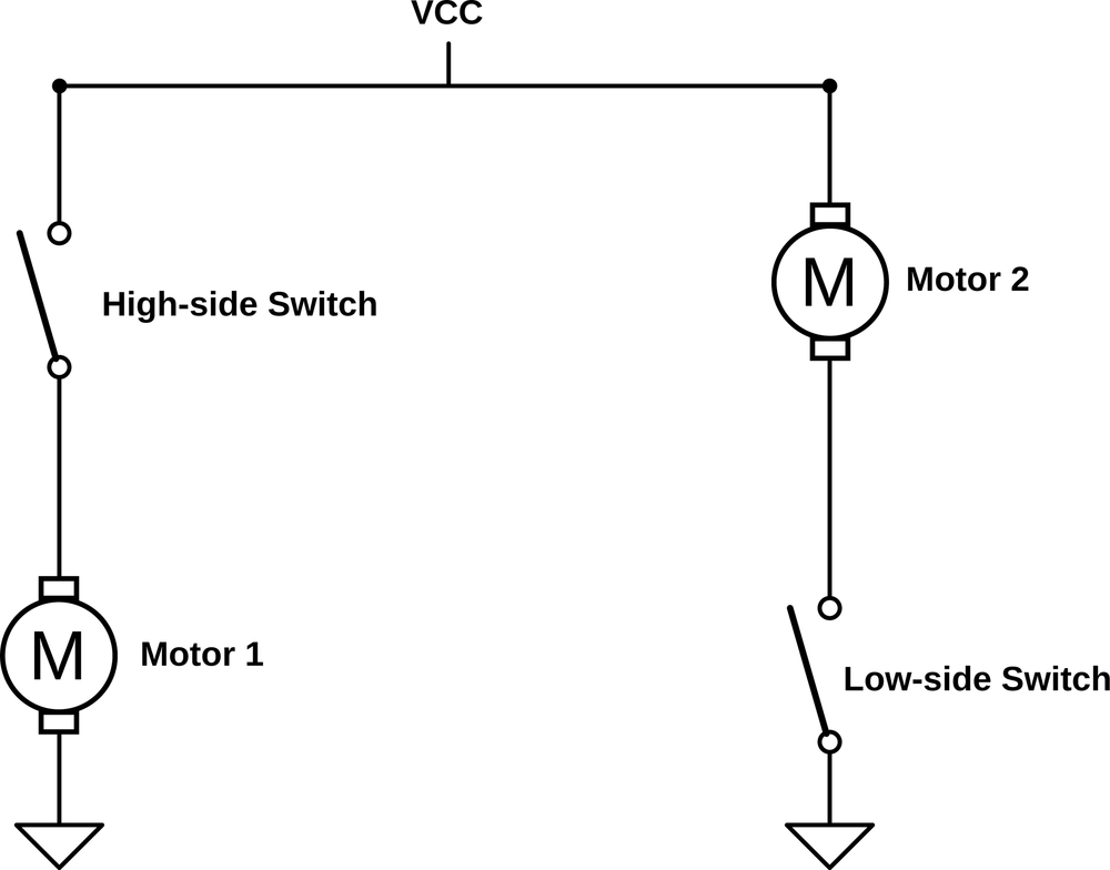
Even in the simplest case, turning a motor on or off with a switch, there are two choices: putting the switch on the high side (higher voltage, “above” or “upstream” of the motor in the circuit) or putting it on the low side (lower voltage, or “below” the motor). These two cases are illustrated in Figure 14-1.
If we’re talking about a switch that you open and close by pressing a
button, the choice is irrelevant—either configuration will stop the
flow of electricity when the circuit is opened, so the motor won’t
run.
Notice that “Motor 1” and “Motor 2” both run when their switches are
pushed closed, but the high-side circuit works by the switch closing
at VCC and the low-side circuit works by the switch closing at
GND.
This distinction between high-side and low-side switching will matter a lot when we use electronically operated switches like transistors, which need a voltage difference to turn on. In the low-side switching configuration, the transistor is connected to ground, and the voltage that you use to switch it on or off is thus relative to ground. When you use a high-side switch, the “ground” voltage level that the transistor sees is whatever voltage is present at the high-side of the motor, which is variable and can be tricky to deal with.
The upshot is that it’s often a lot easier to use a low-side switch if you’ve got the choice.
Let’s look into the different options for switching larger loads in depth.
Bipolar-Junction Transistors
The first transistors to become popular—the ones that displaced vacuum tubes—were the bipolar junction transistors (BJTs). Bipolar transistors can be thought of as a way of taking an input current and using that to allow a much bigger, proportional current to flow between collector and emitter. For most transistors, this current gain is around 100x, which means that if you pass 10 mA through the base, the transistor will allow up to 1 A to flow from collector to emitter. If you reduce the input current to 1 mA, only 100 mA will be able to flow through the transistor. This is the sense in which transistors are amplifiers: small changes in a small current can create big changes in a bigger current.
BJTs are made up of a sandwich of silicon layers that have been positively and negatively charged. Positively doped silicon has ions with a net positive charge mixed in, and vice versa for the negative kind. These are then layered together to make sandwiches with either the negative-doped silicon on the outside (NPN) or the positive on the outside (PNP). Either configuration is a “bipolar junction.” When they’re left alone, the middle layer prevents electrical conduction from the collector to the emitter:
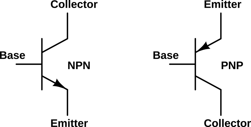
BJTs become interesting under the effects of a control current. Although the middle base layer in the silicon sandwich normally insulates the two outside layers from each other, you can run a current from the base to the emitter, following the little arrow in the circuit symbol. Because of the geometry of the silicon and some quantum mechanics, once your control current introduces free electrons into the base layer, a larger proportional current then flows between the collector and emitter (also in the same direction as the arrows).
For the NPN transistor, you provide the control current by raising the base voltage up above that at the emitter. For the PNP transistor, the control current is created by having the base voltage lower than the emitter. Either way, the effect is the same: a small current between base and emitter allows a much larger current to flow between the collector and emitter.
One disadvantage of using BJTs, from the AVR perspective, is that they’re current-driven. The AVR’s digital outputs are only rated for a few tens of milliamps, so if you are using a transistor with a current gain of 100, the maximum current you can run through the transistor is on the order of one amp. If you need to control more current than that, you either need to buy a transistor with higher current gain or figure out another way to get more drive current. One way to do this is to drive your transistor with another transistor. This is not as crazy as it sounds.
Darlington transistors are just a pair of transistors built together into the same chunk of silicon so that the first one supplies drive current to the second. Because the first transistor amplifies the current that is again amplified by the second transistor, instead of having a gain of around 35–100, Darlingtons have a current gain around 1,000 to 10,000. Now the puny 10 mA that the AVR will put out is able to switch 10–100 A on and off. Hooray!
The other downside of BJTs, and this one is unavoidable, is that they have a voltage drop across the collector/emitter pair—that’s wasted from the perspective of your motor, and it heats up the transistor to boot. If you look at the datasheet for a TIP102, one of my favorite power Darlington transistors, you’ll see that it has a collector/emitter saturation voltage of around 2 V. This means that if you’re driving a motor that’s designed for 12 V and 1 A, you’ll need a power supply of 14 V, and you’ll generate 2 V × 1 A = 2 watts of heat in the transistor. It’s gonna get hot and probably need a heatsink.
Finally, in order to control BJT transistors from the AVR, you’ll have to convert the digital I/O voltage level into a current for the transistor input. And to do that, you’ll use a resistor and Ohm’s law.
MOSFETs
The metal oxide silicon field-effect transistor (MOSFET for short) is a more recently widespread type of transistor. We’re already using a small-signal MOSFET (the 2N7000) in our basic LED-driving setup, and now we’ll take a second to talk more about its inner workings.
MOSFETs work by passing current through a channel of silicon that’s been positively or negatively doped, just like in the BJT. The difference is that the amount of current that is allowed to pass through the channel depends on an electric field that’s imposed on the slice of silicon by putting a voltage on a metal gate plate. The gate doesn’t actually touch the silicon channel layer. Instead, it’s insulated from the silicon by a thin layer of metal oxide, which explains the mouthful of a name. The electrical symbols for MOSFETs are shown in Figure 14-2.
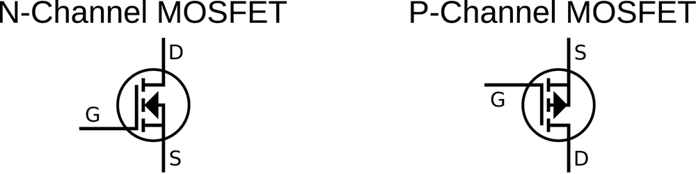
Applying a voltage to the gate creates an electric field that extends through the insulator and into the channel, which makes a thin “inversion layer” in the channel, which is able to conduct electricity. Here comes the bit you need to remember. With an N-channel MOSFET, a positive voltage from gate to source allows a current to pass from drain to source. With a P-channel MOSFET, a negative voltage from gate to source allows current through, from source to drain. In this sense, the N-channel MOSFET is a bit like the NPN BJT, and vice versa.
Unlike BJTs, MOSFETs are voltage-controlled devices, which means that you don’t have to include a base resistor when hooking them up to an AVR I/O pin—just wire up the AVR pin directly to the gate. Even better, small MOSFETs draw very little current when they’re switching on or off, and almost none when they’re in a steady state, so you don’t have to worry about the AVR’s current sourcing capabilities. (This is because the gate is insulated from the channel.) Finally, MOSFETs have almost no voltage-drop when they’re on: even a small-signal switching MOSFET like our 2N7000 has only a couple of ohms of resistance when switched fully on. This means that less power is wasted heating up the transistor and that the load sees the full driving voltage.
Switching MOSFETs are designed to turn on and off quickly, with gate voltages that are between two and four volts. As such, they’re the perfect “switch” to drive in PWM mode with a microcontroller’s pin. Being small and fast, they can’t pass a whole lot of current or withstand very high voltages, but our 2N7000 is good for a couple hundred milliamps at 5 V or 100 ms bursts of 50 mA at 60 V—both situations that the AVR alone couldn’t handle. In short, switching MOSFETs make the ideal next step when your power or voltage demands are just out of reach of the AVR’s digital output drivers.
Power MOSFETs
If you want to power something really beefy, say an electric bike or a heavy robot, you’ll want a specifically designed power MOSFET (or several). Modern power MOSFETs are just like their smaller switching MOSFET cousins, only larger and with a geometry that’s adapted to deliver more current with less resistance, and thus less wasted heat. The trade-off is that power MOSFETs usually require a higher gate voltage to turn fully on and a little more current as well if you’d like to turn them on and off quickly.
As the MOSFETs get bigger and bigger, the area between the gate and the channel gets bigger. To make the same electric field strength inside the channel of the transistor, more charge is needed. In fact, viewed from the gate and source pins, all MOSFETs behave like a capacitor—a certain charge needs to be pushed onto the gate to create a given electric field between the gate and source, just like a capacitor stores charge in the form of an electric field between its two plates.
With power MOSFETs, this gate capacitance limits how quickly the switch can be turned off and on, which puts limits on how quickly you can PWM the MOSFET switch. Small switching FETs have a small gate capacitance and are easy enough to charge up using just an AVR I/O pin’s internal current source, with a gate capacitance in the tens of picofarads, and switching speeds up to 1 MHz. Larger power MOSFETs can have gate capacitances on the order of thousands of picofarads, which means that you’ve got to charge up effectively a 100 times larger capacitor to get the switch open. This means you’ll need more current sourcing capability and probably more voltage to push it through if you want the power FET to switch on at the same speed. The trade-off for the increased gate size is that you get a MOSFET with only 20 milliohms of resistance capable of switching 12 amps at 80 volts.
If you’re truly pushing the high-voltage, high-current, high-frequency PWM frontier, you’ll want a gate driver chip that’s tailor-made to supply the fast charging that the biggest power MOSFETs need. If you just want to drive a fairly beefy (5 A at 12 V) small-robot motor at moderate switching speeds (<20 kHz), you can probably drive it directly from the AVR, or at worst through a switching MOSFET as a first stage.
Relays
A lot of people would start out all this discussion of switches with the relay. After all, a relay is just a switch that’s opened and closed by electromagnet, so they’re easiest to understand. Put a current through a coil of wire, and it pulls a piece of metal into contact with another piece of metal and your switch closes. Done.
The reason relays are near the end of my discussion is that they’re fairly special-purpose these days. They switch on and off comparatively slowly, going click-clack as they physically open and close. This means that PWM is out of the question as a method of control—you can turn a normal relay on and off a couple of times per second, but not much more. And the coils that make the magnetic field take a lot of current. With the exception of precision (costly and sensitive) relays, most require too much current to be directly driven by the AVR’s output pins, so you’ll need something like a MOSFET switch just to run the relay.
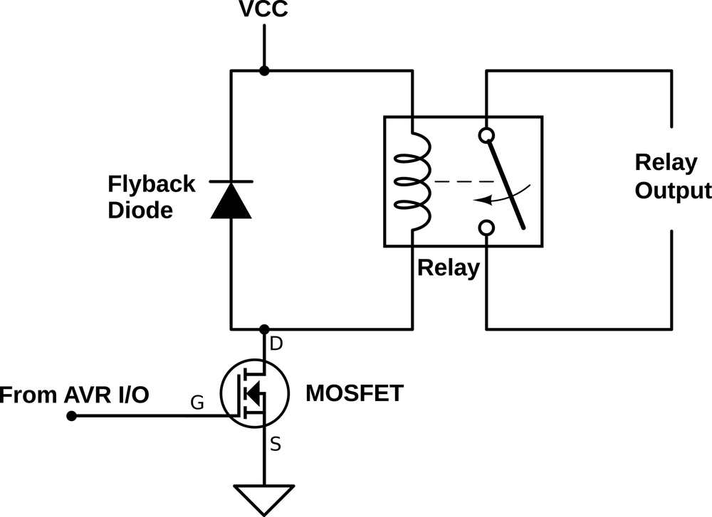
There’s one last thing about relays that’s miserable. Being electromagnets on the inside, they build up a magnetic field. When you turn them off, this magnetic field collapses and generates a reverse voltage, which can be quite large. This reverse voltage can, in turn, fry your MOSFET or even the AVR if you don’t give the reverse voltage somewhere to go. So relays also need a diode in parallel with them to allow for this “discharge” current, as shown in Figure 14-3.
So relays are a niche switch. Where they really shine is when you can take advantage of the fact that they’re physical switches. For instance, if you want to switch a hairdryer or a floodlight on or off, you need to control a lot of (alternating) current at a high voltage. This is a slightly tricky circuit design for solid state, but it’s easy enough to find a 5 V or 12 V relay that is rated to switch these kinds of household appliances on or off, wire it up to an electrical socket, and you’re done. That’s a job for a relay.
Triacs and SSRs
Relays are finnicky, noisy, prone to arcing, not shockproof, and require a bunch of current just to keep them going. You have to build that whole circuit in Figure 14-3 just to drive them. If you really want to get fancy, or if you need to PWM your household appliance, you’re going to want something solid state.
The main contenders here are triacs and solid state relays (SSRs). Triacs are like transistors but used for AC current instead of DC. SSRs are basically triacs with some extra circuitry to help isolate the control side from the AC line voltage. Many (most?) SSRs have an LED on the control side and a light-sensitive triac on the AC side, so that turning on or off a washing machine looks to your AVR like blinking an LED; but because there’s no direct electrical connection between the AVR side and the wall-voltage side, there is no corresponding electrocution hazard, and that’s a darn good thing.
We won’t be using either of these in our projects here, but if you ever need to control a wall-voltage device from the AVR, you should look into an SSR. I used one once, along with a temperature sensor, to regulate the heater in an electric coffee roaster.
Switches: Summary
If you want to control real power with the AVR, there’s a number of switch-like devices out there that will help you do it. What you need to use will depend on the specifics of the motor or laser or home appliance you want to run.
For providing power to small-robot DC motors, BJTs—particularly Darlington BJT circuits—can work just fine. If you need more current, the advantages of a (more complicated) power MOSFET circuit become more apparent. Keep both of them in mind.
Small switching MOSFETs, like the 2N7000 that we’re using, are great for driving small-to-medium loads, even if you have to use a few in parallel. We’ll be using a 2N7000 to drive the laser in the laser-sundial application, and for driving power MOSFETs.
Finally, when you need to control house-voltage AC currents, you’ve got two main choices. If you’re doing low-frequency switching, it’s hard to beat the simplicity of a relay driven with a switching FET. If you need to turn the device on and off a lot, you’ll want an SSR.
A summary of all of the possible switch choices can be found in Table 14-1.
| Type | Activation | Voltage gain | Current gain | Voltage type | Main use |
Bipolar | Current | High | Lower | DC | Amplifying voltage signal |
Darlington | Current | Very high | Can be high | DC | Amplifying, sourcing current |
FETs | Voltage | Lower | High | DC | Sourcing current |
Relay | Current | - | - | AC or DC | Literal switching |
SSR | Voltage | - | - | AC | Medium-speed PWM |
DC Motors
The simplest motor that we’ll deal with is the plain-old DC motor. A DC motor takes a voltage across its two inputs, alternately charges up two internal electromagnets, and uses the resulting magnetic force to spin a shaft. If you reverse the sense of the voltage, the motor spins the other way. If you apply more voltage, it’ll turn faster (within limits). DC motors are great for spinning things relatively fast when positioning precision doesn’t matter; when they are geared down, they turn more slowly but provide more torque. A geared DC motor is probably what you want to use to drive the wheels of your robot or automatically raise and lower your windowshades.
If DC motors are so simple, there shouldn’t be all that much to say about using a microcontroller to drive DC motors, right? Not necessarily! Grab yourself a small motor to play around with, strap on your 2N7000, construct the circuit in Figure 14-4, and let’s run some experiements.
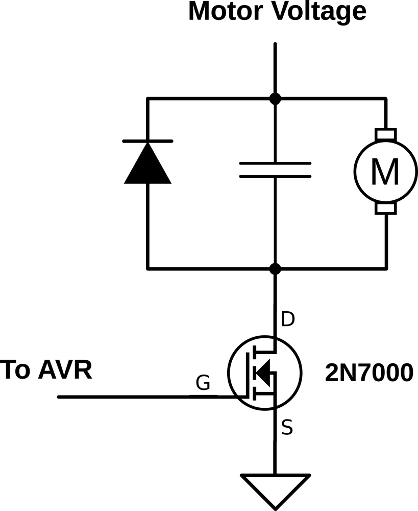
First, look over the circuit in Figure 14-4 and
Figure 14-5. You should recognize this as the
low-side switch configuration, with a motor in the middle: one side of
the motor is connected directly to VCC and the other side to the
2N7000 switch that is connected to ground. The flyback diode in Figure 14-4 is important to provide a path for the current that’s
flowing through the motor to continue on after we’ve switched the
motor off. Finally, the optional capacitor smooths out noise that the
DC motor itself makes as the brushes inside switch from one polarity
to the other.
If you’re using a separate voltage source for the motor, like a battery, be sure to connect the negative pole of the battery to your circuit ground, and the positive end directly to the motor as shown in Figure 14-5. Notice that the battery ground and the MOSFET’s ground are both connected to the AVR’s circuit ground. This gives the AVR, its power supply, the 2N7000, and the battery the same reference voltage.
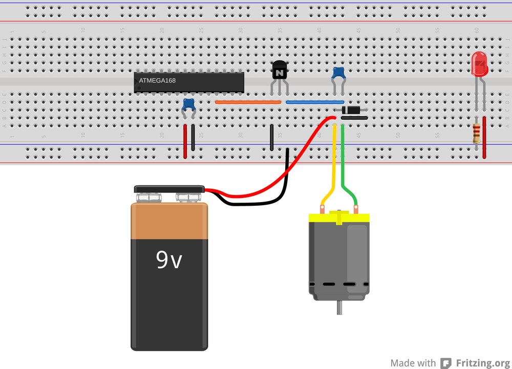
As a first experiment, hook up the transisor, motor, diode, and capacitor as in Figure 14-4. If you don’t have a battery handy, and your DC motor will run on the breadboard’s 5 V, feel free to connect the high side of the motor directly into the power rail. This circuit is temporary anyway, so feel free to use alligator clips to hook it all together wherever you need to.
Now, without any code in the AVR, you can verify that you can control the motor by applying 5 V and 0 V to the gate of the transistor through a wire. Pull out the AVR side of the wire that connects the gate of the MOSFET to the AVR. Tap it alternatively to the 5 V and ground power supply. You should see the motor start to spin when you connect the wire to 5 V, and stop spinning when you connect it to ground. This is exactly what we’ll have the AVR doing in a few minutes.
What happens if you just hold the wire in your fingers? MOSFET gates take very little current to turn on and off, and you may be coupling enough voltage from power line radiation to turn it on. If not, try alternately touching your 5 V power supply and then ground with your free hand. You’ll find that your body charges and discharges enough to flip the switch.
Now let’s put the motor under the AVR’s control. Reconnect the gate of the 2N7000 transistor to pin PD5 as in
Figure 14-5, and we’ll use Timer 0 and the output
compare pin functionality to experiment with simple DC motor driving.
If you’ve still got that circuit set up, the transistor is already
hooked up in the right place.
Flash in the code and then you can start playing around with your motor. Driving a motor with signal-switching FETs is a little bit sketchy, so you might want to keep a finger on the MOSFET and see if it warms up excessively. It shouldn’t get hot unless you’re putting the motor under a load, though. Let’s look at the code in Example 14-1.
/* Demos PWM control of a DC motor */// ------- Preamble -------- //#include <avr/io.h>#include <util/delay.h>#include <avr/interrupt.h>#include "pinDefines.h"#include "USART.h"#define SPEED_STEP_DELAY 2/* milliseconds */// -------- Functions --------- //staticinlinevoidinitTimer0(void){TCCR0A|=(1<<WGM00);/* Fast PWM mode */TCCR0A|=(1<<WGM01);/* Fast PWM mode, pt.2 */TCCR0A|=(1<<COM0B1);/* output PWM to pin */TCCR0B|=(1<<CS02);/* Clock with /1024 prescaler *///TCCR0B |= (1 << CS00); /* Clock with /1024 prescaler, pt.2 */}intmain(void){uint8_tupdateSpeed;// -------- Inits --------- //initTimer0();OCR0B=0;ANTENNA_DDR|=(1<<ANTENNA);/* now hooked up to MOSFET, output */LED_DDR|=(1<<LED0);LED_DDR|=(1<<LED1);initUSART();printString("DC Motor Workout");// ------ Event loop ------ //while(1){updateSpeed=getNumber();/* Ramp up/down to desired speed */if(OCR0B<updateSpeed){LED_PORT|=(1<<LED0);while(OCR0B<updateSpeed){OCR0B++;_delay_ms(SPEED_STEP_DELAY);}}else{LED_PORT|=(1<<LED1);while(OCR0B>updateSpeed){OCR0B--;_delay_ms(SPEED_STEP_DELAY);}}LED_PORT=0;/* all off */}/* End event loop */return(0);/* This line is never reached */}
There’s nothing particularly new in the code, and I copied a large
part of it straight from other examples. I just wanted to write
something that you can get a feel for driving motors with. (Once
you’ve gotten a library of working examples for yourself, you’ll find
that this kind of code reuse is phenomenally handy.) The Timer 0
initialization routine is taken straight from our PWM examples; it
sets up the timer to output the PWM waveform on pin PD5. The
getNumber() routine takes in a number (as ASCII characters) that’s
sent over the serial line.
The main event loop waits for you to type in a PWM value over the
serial line and then adjusts the OCR0B register smoothly up or down
to that value, lighting up LEDs for acceleration or deceleration,
respectively. As befits a simple demo program, almost all of the time
is spent sitting and waiting for you to type something in.
The real point of the program, though, is to get you familiar with driving small DC motors by PWM, so flash this in and start typing PWM duty-cycle values. Hit Return after each one, and it’ll ramp up the motor.
The first thing to notice is that, although the PWM duty cycle will vary the percentage of the time that the motor is powered, that is not the same as controlling the speed. With my different motors, they would start turning only in the 20–60 (out of 255) range, even at their proper working voltages. Motors, and especially gearmotors, have different internal frictions and coil inductances that make them unique.
Next, change the clock prescaler in initTimer0. First, just try
commenting out the TCCR0B |= (1<<CS02); line to change from prescaling by 1,024 to 256.
At 1,024, the PWM frequency is a fairly low 31.25 Hz. At low duty
cycles, you may be able to hear the individual pulses. At a
prescaling of 256, you should be able to hear a low hum coming from
the motor windings—the PWM frequency is around 125 Hz. Look at the
datasheet where it describes the possible clock settings and
experiment with them all. As you increase the PWM frequency, you’ll
notice that the range of duty cycles over which the motor runs will
change. How different motors respond to different PWM drive
frequencies depends a lot on the winding resistance and inductance,
which varies from motor to motor, as well as the driving voltage.
Finally, you can experiment with how quickly your motor changes speed
when driven at different duty cycles. The macro definition #define
SPEED_STEP_DELAY 10 sets the rate at which the PWM duty cycle
changes. If you set this to zero, the PWM will change as soon as you
hit Enter and transmit the new value. If you set it higher, the motor
will ramp up more slowly. Try to imagine what would happen if you
had this motor and a wheel on a robot or vehicle. Think about what
kinds of accelerations it can handle. Load the wheel down with your
hand. (Or if you’ve built a bot already, playing around with code
like this will let you discover your traction limits.)
Motor Specs
If you’re buying a motor, there are a couple of specifications that you should know about. The first spec is the rated voltage. Most DC motors will run +/– 50% of their rated voltage, but you want one that matches your power source, or vice versa. For small bots, look for something in the 3 V to 12 V range to match your batteries.
The other spec is stall current, which is just the rated voltage divided by the coil winding resistance. Stall current is the maximum current that the motor will draw when it’s just starting up (or when it’s stalled out) and the back voltage is at 0 V. The transistor that you’re running the motor with should be able to deliver at least this much current, if not a little more as a safety margin.