
Chapter 3. Digital Output
If you got the project from Chapter 2 running, you’ve gotten yourself a little bit familiar with the AVR toolchain. You’ve hooked up a simple circuit on the breadboard, and you’ve seen the first sweet blinkies of success! Now you’re ready to take the next step: even more blinkies blinking even faster, and looking at what’s going on under the hood.
The project for this chapter is a persistence-of-vision (POV) pattern generator. By turning eight LEDs on and off really quickly, the POV toy exploits your eye’s slow response to light in order to draw patterns that seem to float in midair when you scan your eyes across the LEDs. For an example of how this looks, see Figure 3-1. POV toys are fun, and you’ll have something neat to show for your efforts at the end of the chapter. You could spend an entire rainy Saturday making up neat patterns to display on the POV toy. (Don’t ask me how I know!)

Digital output is both the simplest and most common way that your microcontroller programs are going to control other devices in the outside world. By setting the voltage on an AVR pin, you can light an LED or activate a circuit that turns a motor on or off. So as we’re going through these exercises, if you’d like to think of each LED as standing in for a motor you’d like to turn on, or a switch you’d like to flip somewhere, I won’t stop you from daydreaming.
Along the way, you’ll learn how to configure the AVR’s pins to output a digital logic voltage, a bit about how the AVR represents numbers as eight-bit binary bytes, and some of the basics of writing code in C. That’s a lot to cover, so lets get to it!
blinkLED Redux
Before we take on anything truly new, let’s have a look at the code that’s hopefully still blinking away inside the chip on your desktop, because we’ll be expanding on that program in this chapter. See Example 3-1 to refresh your memory.
/* Blinker Demo */// ------- Preamble -------- //#include <avr/io.h>/* Defines pins, ports, etc */#include <util/delay.h>/* Functions to waste time */intmain(void){// -------- Inits --------- //DDRB|=(1<<PB0);/* Data Direction Register B:writing a one to the bitenables output. */// ------ Event loop ------ //while(1){PORTB=0b00000001;/* Turn on first LED bit/pin in PORTB */_delay_ms(1000);/* wait */PORTB=0b00000000;/* Turn off all B pins, including LED */_delay_ms(1000);/* wait */}/* End event loop */return(0);/* This line is never reached */}
The Structure of AVR C Code
Looking over the blinkLED.c code, notice that the code falls into the following rough sections:
[preamble & includes]
[possibly some function definitions]
int main(void){
    [chip initializations]
    [event loop]
    while(1) {
      [do this stuff forever]
    }
    return(0);
}
The preamble is where you include information from other files, define global variables, and define functions. If you’re going to be using a library of functions from some other source, or even just reusing your own code, this is where you’ll do it.
After the preamble comes the main() function. The name “main” is
special—regardless of how many other functions are defined, your C
program must have exactly one main() function. main is where the AVR
starts executing your code when the power first goes on. It’s the
entry point.
Inside the main function you’ll find a while(1) loop, often
referred to as the “main loop” or “event loop.” while() loops are
loops that continue running over and over as long as the condition
inside the parentheses is true. And in C, 0 always resolves as
false, and 1 always resolves as true. So everything that’s within
this loop will run over and over again forever. As long
as you’re giving the AVR microcontroller power, it’s going to keep
going round and round the main event loop, turning your one LED on
and off until it burns out.
Hardware Registers
Now we get down to actually doing something in the code. The lines
that are mostly in all caps (DDRB = 0b00000001;) need some
explaining. Let’s tackle the left side first. DDRB and
PORTB are definitions that point to the AVR’s internal hardware
registers.
As mentioned in Chapter 1, almost all of the pins on the AVR chips are configurable as either input or output pins. That is, they can be internally hooked up as either voltage-sensing components or as transistor switches that will connect the pin through to the VCC or GND voltage levels. The way we’re going to configure the pins as either input or output is deceptively simple in code—assigning a variable a certain value—but what goes on inside the dark wiring heart of the chip is interesting.
When you save a value in a “normal” variable, for instance with code
that looks something like a = 7, the compiler picks a free slot from
the chip’s available RAM, calls that slot “a”, and stores the value
7 there. Later on, when you add one to your variable a = a + 1;
the compiler looks up “a” to see in which slot in memory it stored the
value, pulls the value out of the memory slot, adds one to it, and puts
it back in its slot. (For much more detail about the AVR’s use of
memory, see Chapter 19.)
Each slot in the AVR’s memory is a byte, and each byte has eight bits. For a “normal” RAM location, these bits are used to encode (in binary) the number you’d like to store. Inside the chip, each bit in RAM is hooked up to a network of transistors that keep whatever electrical state was last imposed on them. The ATmega168, for instance, has 8,192 of these single-bit memory networks, or 1,024 bytes of RAM.
When you want to configure a microcontroller pin, it looks the same in
code as saving a value into a variable. And that’s because the same
thing is going on inside the chip. The chip’s hardware registers are
just like the RAM storage slots that you use for variables, only they
each have side effects. So when you write DDRB = 0b00000001;, you’re
not just storing the number one in a memory location; you’re also
flipping the transistor switches that are directly wired to each of the
eight memory cells.
Inside the AVR chip, the data-direction register (DDR) memory locations are physically wired up to the transistor switches that determine whether a given pin is in input or output mode. When you write the numeric value one to that register, it’s remembered. But it doesn’t end there—the register’s output is additionally connected to two switches. When a one is stored in that register bit, the output switch is closed, the input switch is open, and the pin is configured as output. When a zero is stored in that bit in your code, the output switch is open, the input switch is closed, and the pin is configured as input.
Because hardware registers are special memory locations, the
compiler can’t treat them exactly the same as variables. When you
create a normal variable, the compiler can pick any convenient place
in memory for it. Because the hardware registers are physically
connected to the input/output circuitry, the location can’t change.
These register locations are spelled out in the io.h header file so
that we don’t have to remember their numerical value, but rather
mnemonic names like DDRB, for “data-direction register B.” Anyway,
the upshot is that, once you’ve included the io.h file in your code,
you can treat the hardware registers like normal variables and write
code like DDRB = 0b00000001;, DDRB = 23;, or DDRB = DDRB + 7;.
Hardware registers: the bottom line
Whether or not you care about what’s going on deep under the hood inside the chip, you need to take away two things from all this: hardware registers can be accessed just like “normal” variables from your code, but inside the chip they have extra connections that let them influence the way the rest of the chip behaves.
Consequently, when you need to tell the chip to put out a high voltage
level on a given pin, it ends up being a matter of figuring out which
number corresponds to the bits that correspond to the pins you’d like
activated, and then writing that number into memory. Try to think of
each register as being a row of eight switches, and writing a number
into that register is the equivalent of flipping some of the switches. In particular,
if you know how your number is represented in binary, each of the
bits that has a 1 in it is a switch turned on, and each 0 is a switch
turned off.
The three most important hardware registers
Each bank of pins (B, C, and D on the Mega series AVRs) has three
hardware register memory locations associated with it. Let x stand
for each bank’s letter: so DDRx will be DDRB, DDRC, or DDRD
depending on which bank of pins you mean:
-
DDRxdata-direction registers (port x) - These registers control whether each pin is configured for input or
output—the data direction. After a reset or power-up, the default
state is all zeros, corresponding to the pins being configured for
input. To enable a pin as output, you write a one to its slot in the
DDR. -
PORTxport x data registers When the
DDRxbits are set to one (output) for a given pin, thePORTregister controls whether that pin is set to logic high or low (i.e., theVCCvoltage or ground). Switching between these voltage levels could, for instance, turn on and off attached LEDs.With the
DDRconfigured for input, setting thePORTbits on a pin will control whether it has an internal pull-up resistor attached or whether it’s in a “hi-Z” (high-impedance) state, effectively electrically disconnected from the circuit, but still able to sense voltage. We’ll talk more about this in Chapter 6.-
PINxport x input pins address - The
PINregister addresses are where you read the digital voltage values for each pin that’s configured as input. EachPINxmemory location is hooked up to a comparator circuit that detects whether the external voltage on that pin is high or low. You can’t write to them, so they’re not really memory, but you can read from thePINxregisters like a normal variable in your code to see which pins have high and low voltages on them.
All of these hardware registers are readable, so you can always query
the input/output direction or state of any pin at any time. The PINx
addresses aren’t writable, because they just reflect the voltage
values (high or low) on the corresponding pins.
Configuring output: DDRs, PORTs
Let’s quickly step through what you need to do in order to light up some LEDs. When an AVR chip first gets power, it starts off in a default state with all its pins in input mode, with the pins essentially electrically disconnected from the circuit. To output a voltage on a given pin, you’ll need to:
-
Configure the relevant pin for output mode by writing to
the data-direction register (
DDR). -
Assign a high or low value to the individual pin by writing to the
PORThardware register.
Get Your DDRs, PINs, and PORTs Straight!
A common beginner mistake, and one I even make from time to time, is
trying to write to the PORT register and expecting a voltage out
when the DDR hasn’t been set to output yet. So when you’re
debugging your code, and can’t figure out why the LEDs aren’t lighting
up, the first thing you should do is make sure that you’ve enabled the
pins in question for output.
The other related gotcha is forgetting which register you’re writing
to—writing to the DDR or the PIN registers when you want to be
writing to the PORT register, for instance. Try to think of the
PIN registers as "Port INput,” and the PORT registers as
"Port Output Register Thing.”
When things aren’t working as expected, double-check the logic of your
DDRs, PINs, and PORTs!
blinkLED Summary
Look back at the blinkLED.c code, and make sure you know what’s
going on. The first two lines include files that are part of the AVR
standard C library. <avr/io.h> is the file that defines all the
PORTs and DDRs. <util/delay.h> provides us with the
_delay_ms() function that we use to delay between blinks. You’ll end up including a
few more of these AVR library files as we move through the book.
int main(void) starts the main function—when the microcontroller
starts up, it’ll start here. Unlike big-computer programs, the
microcontroller main() function usually never returns. We’ll
initialize our variables, configure the chip, and then enter a
neverending event loop.
Our initialization here consists of writing a 1 in one bit of the
DDRB register, which is enough to set up that pin as output. And
then, in the event loop, we go back and forth between turning on and
off the first LED by writing a 1 to the bit in the PORT
register that’s connected to our LED, with a delay to make it
visible. That’s the one-two combo for setting up digital output.
POV Toy
That should be more than enough detail about how to blink a single LED on and off slowly! Now let’s take some time to solidify all that information and make something cool with it. Specifically, a programmable POV toy.
With all this newfound bit-twiddling power, it’s time to show off a little. POV toys are pretty neat, and take our LED-blinking skills up to the next level. POV stands for persistence of vision, the phenomenon in which an afterimage persists on the retina for approximately 1/25 of a second. The point with a POV toy is that you turn LEDs on and off so quickly that the eye can’t react to them. If you swing the device around, the afterimage patterns that they make seem to float in the air. They’re pretty cool, and the only thing cooler is one that’s loaded up with patterns you made yourself.
Building the Circuit
In building the blinkLED circuit from the previous chapter, you’ve already
hooked up an LED and resistor to PB0 on the AVR. For the POV toy,
you’re going to need to do that seven more times. At some point, it
becomes convenient to solder the LED and the resistor together
directly, because they’re always used together anyway. If you’d like to
take a 10-minute soldering break, make yourself some blinkenlights.
Blinkenlights
You’re going to want to test voltages all of the time to make sure that everything is working as you expect, and for digital circuits the easiest way is to light (or not!) an LED. But LEDs can burn out if you run too much current through them, so we almost always add on a current-limiting resistor. So warm up your soldering iron, and take a few minutes to make yourself some tools—LEDs with integrated resistors used for diagnostic purposes: blinkenlights. (Look up “blinkenlights” on Wikipedia if this doesn’t ring a bell.)
To make a blinkenlight, all you’ll need to do is clip the negative/cathode side of the LED short and solder on an appropriate resistor. If you’re only going to be using 5 V, a 220 ohm resistor will work fine. But for maximum utility, use something like a 1,000 ohm resistor, and you’ll be able to light the LED off sources up to 15 V without fear of burning out your LED. Figure 3-2 shows you the three simple steps.

If you’re going to be working through this book with a breadboard, you’ll need 8 LEDs for the POV toy project alone, so go ahead and make 10 or 12. Everywhere in our circuit diagrams that you see an LED and a resistor, you can substitute a blinkenlight. Having the resistors prewired can save you a bunch of extra connections on your breadboard.
When you’re done with this book and you start up a new project, attach a blinkenlight to the power lines of your breadboard to use as a power indicator. Then you’ll never have to worry about whether the breadboard is “on” or not. Scatter them liberally around your breadboard wherever you want to test a logic value (and the current draw of 20 mA isn’t too excessive). Making 10 or 12 may seem like a lot at once, but trust me; you’ll find a use for them all someday. If you’ve got LEDs of different colors, make a few of each. Go nuts!
Simplest POV Toy
The simplest version of the POV circuit is just eight LEDs,
each with its own current-limiting resistor, all hooked up to the pins
PB0 through PB7 on the AVR. This way, you can write a one to selected
bits of the eight-bit byte in PORTB, and the corresponding LEDs will
light up. Hook up the circuit shown in Figure 3-3.
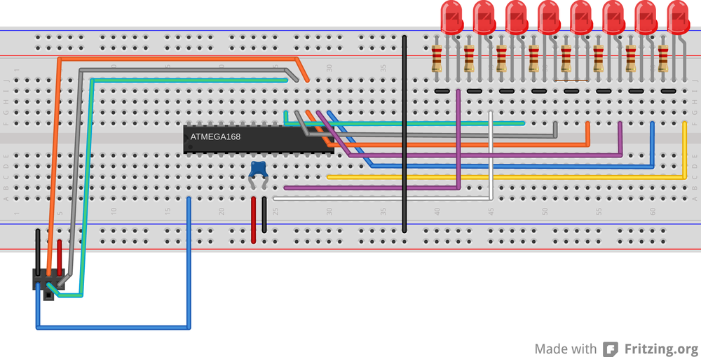
Notice that the AVR’s pins aren’t necessarily all laid out in a nice row. PB0
is around the corner from PB1 through PB5, and then you have to cross back
over the chip again to get to PB6 and PB7. Pay attention to this strange
ordering, or else the resulting images won’t look right! If you need a
refresher, look at the pinout diagram in Figure 2-5.
For instant gratification, temporarily unplug the black wire that connects the bottom ground rail to the top ground rail that has the LEDs plugged into it. Now flash your code into the AVR and reconnect the black wire between the ground rails again. You should see the LEDs spring to life! Success. Sort of.
Now try to flash the code into the chip again. It will very probably fail, and the chances of success depend on the interior electrical details of your flash programming setup and your choice of current-limiting resistors for the LEDs. What’s going on? Well, you see those three AVR pins that are shared between the LEDs and the programmer? The LEDs are interfering with your programmer-to-AVR communication. When the programmer tries to write a logic-high voltage to the AVR or vice versa, the LEDs can draw enough current to pull the voltage down and turn ones into zeros.
When you’d like to reflash the chip, pull out the ground wire on the LEDs again. Now they’re not connected into the circuit, and communication between AVR and programmer is normal. And then when you want to see the LED output, plug the black wire back in.
MOSFET trickery
After you’ve done the disconnect-program-reconnect-blink dance enough times, you’ll start to get bored of it. You could connect a two-way switch in place of the black wire, flipping it one way to enable the LEDs and the other way to enable the programmer. A nice twist on this idea is to use an electrical switch to automatically connect and disconnect the LEDs for you. In our case, the electrical switch that we’ll use is a 2N7000 MOSFET.
(If you got “lucky,” and you’re able to program the AVR’s flash with the LEDs still connected, you might be tempted to skip the MOSFET. You can do that at your own risk—just remember later on when you have random trouble flashing the AVR that I told you so. You can always test out if this is the case by temporarily pulling the ground wire that supplies the LEDs.)
What Is a MOSFET?
A MOSFET is a transistor. We’ll be using it in full-on and full-off modes, so for now you can think of it as an electrically controlled switch. All MOSFETs have three pins, and we’ll almost always connect one (the source pin) to ground and another (the drain) to the part of the circuit that we’d like to turn on and off. This switching action is accomplished by putting a voltage on the remaining pin, the gate.
Inside the MOSFET is a channel that connects the source to the drain. The gate lies physically between them and is a metal plate that’s insulated from the drain-source channel. Voltages applied to the gate actually attract or repel electrons in the channel, making it more or less conductive. At the extremes, it’s like an open circuit (disconnected) when there is no voltage on the gate, and very conductive with five volts on the gate.
We’ll cover FETs in much more detail in Chapter 14.
Back to our wiring-up problem. We’d like our MOSFET switch to
automatically disconnect the LED’s ground rail when we’re programming
the AVR, and reconnect the ground rail so that the chip can blink
LEDs when we’re done programming. The clever bit in this next circuit
uses the fact that the AVR uses its RESET pin to enter programming
mode. And we have the good luck that the RESET pin (PC6, blue
wire from the programmer) is held at 5 V by the AVR when the chip is
running, and pulled low to 0 V by the programmer to signal the AVR to
enter programming mode.
We can thus connect the MOSFET to the AVR’s RESET pin and use the
RESET action to connect and disconnect the LED’s ground rail. When
the AVR is running normally, the RESET pin is pulled up to 5 V and
the gate on the MOSFET is pulled up along with it. This closes the
MOSFET switch, which connects the ground rail from the LEDs to the
circuit ground and the LED’s blink. When the programmer pulls the
RESET line low, it simultaneously sets the AVR into programming mode
and also draws the gate of the MOSFET to ground, opening the MOSFET
switch and disconnecting the LEDs. See Figure 3-4 for a breadboard wiring diagram.
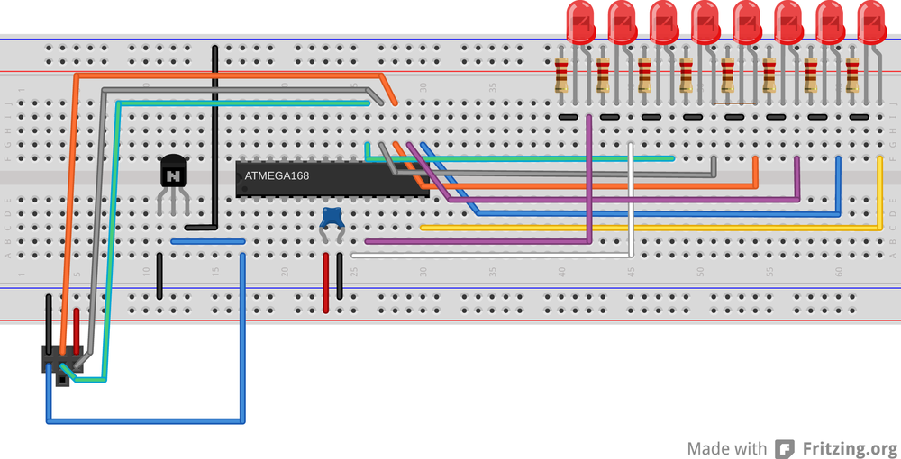
When hooking up this circuit, notice that the MOSFET has a front side
with a flat face and part labelling. If you’re looking at it
front-on, the far left pin is the source that gets connected to
ground. The far right pin on a 2N7000 is the drain, which gets
connected to the LED’s ground rail. The center pin is the gate pin,
which controls the switching action and gets connected to the AVR’s
RESET pin, PC6.
If you don’t have a suitable MOSFET lying around, you can make do with a manual switch if you have one, or just keep plugging and unplugging the ground wire. We’re going to be using 2N7000s for a number of tasks throughout the book, though, so it’s a good time to order some.
Pretty Patterns: The POV Toy Code
OK, that was a lot of detailed wiring-up. If you’re feeling brave, you can now
play around with a full byte’s worth of LEDs and modify the blinkLED.c code to
display whatever blinking patterns you’d like. What would happen, for instance,
if you replaced PORTB = 0b00000001; with PORTB = 0b01010101;? Or
alternate between PORTB = 0b10101010; and PORTB = 0b01010101; with a small
delay in-between? You could start to make animations.
Flash the povToy.c code into the chip and see what happens. If it’s not convenient to shake the breadboard around, try turning off the lights in the room and running your eyes across the tabletop with the device on it. The trick is to not focus on the blinking lights, but rather to let them trace their pattern across the back of your eyes. Try jumping your eyes between a point a foot or two to the left of the POV toy and a point a foot or two off to the right.
Once you get tired of my preprogrammed pattern, it’s time to work through the code in Example 3-2 so that you can create your own!
// POV toy demo framework //// ------- Preamble -------- //#include <avr/io.h>#include <util/delay.h>// -------- Functions --------- //voidPOVDisplay(uint8_toneByte){PORTB=oneByte;_delay_ms(2);}intmain(void){// -------- Inits --------- //DDRB=0xff;/* Set up all of LED pins for output */// ------ Event loop ------ //while(1){/* mainloop */POVDisplay(0b00001110);POVDisplay(0b00011000);POVDisplay(0b10111101);POVDisplay(0b01110110);POVDisplay(0b00111100);POVDisplay(0b00111100);POVDisplay(0b00111100);POVDisplay(0b01110110);POVDisplay(0b10111101);POVDisplay(0b00011000);POVDisplay(0b00001110);PORTB=0;_delay_ms(10);}/* end mainloop */return(0);}
At the base of the POV toy routine is a really simple function, POVDisplay(),
but if it’s the first function declaration in C you’ve ever seen, it’s worth a
short explanation.
Let’s look at what the POVDisplay function does. It takes in a single byte
and then turns around and writes it straight back out to the PORTB. This is
just like what goes on in blinkLED. Every bit that’s set to a one in the
number we pass to POVDisplay has a corresponding illuminated LED. Here, we
also delay for a few milliseconds to display the pattern for just a tiny bit.
Now look down at the main() functions. The first step to using the AVR’s
digital outputs is to configure the data-direction register (DDRB) so that any
subsequent values written to the PORTB register will appear as either high or
low voltage values on the corresponding pins.
Functions in C
When your code gets to the point that it’s doing many, many different things, it can really help both the readability and the logical flow to encapsulate whatever parts of it you can into functions. In C, a function takes a number of variables as arguments, or inputs, and returns either nothing or a single value as a result. Each time you call the function from any other place in the code, the code inside the function is run.
Variables that are defined within the function stay in the function (this is
called their scope) and aren’t accessible outside the function’s context, so
you don’t have to worry about one i overwriting another. Variables that are
defined outside the function can be changed by code within the function.
C insists on knowing the type of each of these arguments and return values. In
this example, POVDisplay() is a function that takes in an unsigned integer
(uint8_t) variable as its input, uses the input to set the LEDs, and then
waits. It doesn’t return any values, hence the void in it’s definition.
If you’re new to C, you’ll see a lot more function definitions throughout the rest of the book, and you’ll pick it up as we go along.
The event loop is where the action happens. The POVDisplay() function is
called repeatedly with a binary value. I could have written this part of the
code using the decimal representation of these numbers, but if you squint your
eyes just right and tilt your head, you can almost see the pattern that’s
displayed in the ones and zeros. (How readable would it be if I wrote
POVDisplay(189);? Quick, which LEDs are on and which are off?)
After displaying the desired pattern, all of the LEDs are turned off with
PORTB=0; and a relatively long delay time separates one run of the pattern
from the next. Then the infinite while() loop starts up again at the top.
Experiment!
Now I’d like you to start messing around with the code. Increase the delay
inside the POVDisplay() function so that it’s long enough that you can see the
individual steps. Compare them to the binary values getting written to the
PORTB register. See how numbers being written around in your code is making
electrical things happen in the real world. Experience the zen of hardware
registers.
How short can you make the delay before you can no longer swing your arm (or
move your eyes) fast enough to see the pattern anymore? If you need to decrease
the delay down below one millisecond, there is a _delay_us() function that
delays in increments of microseconds, or thousandths of a millisecond.
Finally, and here’s the part where I lost a Saturday afternoon, try coding up some of your own patterns using this simple function. I found that it helps to draw out the patterns horizontally across eight rows of graph paper first, and then read the binary numbers out down the vertical columns.
In the povToy directory, I’ve included some more examples and even an example POV font so that you can easily spell words. The code for running all of these is a little advanced for the first serious chapter of this book but was written with easy extensibility in mind, so feel free to flash them in or modify them and see what happens.
The easiest way to program in another bit of
code from within the same directory is to edit the makefile and change the
target from MAIN = povToy.c to something like MAIN = 1up.c or whatever.
Alternatively, if you’re running make from the command line, you can just type
make MAIN=1up.c flash and it will compile the new code and flash it into your
microcontroller without having to touch the makefile.
If you’ve made some patterns that you’re really proud of, you’ll want to show them off to other people. You may want to make this whole setup a little bit more portable, and the easiest way to do that is to unplug the flash programmer and supply power using batteries.
Once you’ve exhausted all of the eight-LED POV possibilities, pick up again with the next chapter where you’ll learn a much more flexible method of controlling the AVR’s output from code.