
Chapter 13. A Level 3 Rocket
There are many ways to build a Level 3 rocket. Some people like to build rockets that get the most out of every newton, reaching for high altitude or fast speeds. Others like to build very large rockets. The rocket we’ll look at in this chapter (Figure 13-1) is a bit of a compromise. It’s a fairly standard design, but it’s packed into a roomy 4”-diameter fiberglass airframe so you have plenty of room to work. It will stay below 15,000 feet on an AeroTech M1297W, but it will also do about Mach 1.5.
Figure 13-1. The author prepares Ganymede for a flight at BALLS 23.
Ganymede
Ganymede is an all-fiberglass rocket with a classic high-power rocket design. In many ways, it is very similar to the dual-deploy version of Phobos, a fact that will make this chapter considerably shorter than most of the construction chapters in the book. This chapter assumes you are familiar with all of the information from earlier in the book, especially the construction details for Phobos, the safety tips regarding working with fiberglass, and rockets that use dual deployment with a drogue and main parachute.
There are several companies that supply fiberglass parts for rockets. Ganymede uses parts from Madcow Rocketry. The parts list is shown in Table 13-1. As you know by now, you can make many substitutions to this basic parts list. Depending on what other motors you might want to use in the future, you might choose to make the booster a bit longer. Madcow Rocketry also sells colored versions of its fiberglass tubes. Other than color, they are the same tubes used here. If you don’t like paint for some reason, the colored tubes could save you from a boring rocket.
| Part | Description | Part number |
|---|---|---|
Nose cone |
The nose cone for the rocket. Madcow sells several kinds, and all will work. |
4” Filament Wound Metal Tip 4:1 Ogive |
Booster airframe, 4” diameter, 45” long |
Sold in either 30” or 60” lengths. |
4” G12 Airframe |
Payload airframe, 4”, 24” long |
Sold in either 30” or 60” lengths. |
4” G12 Airframe |
Switch band, 4”, 1” long |
Cut this from the airframe or booster tube. |
4” G12 Airframe |
Tube coupler, 12” long |
Fiberglass tube coupler for 4” airframe tubes. This is sold in several lengths. Get the 12”-long part. |
4” G12 Coupler |
Coupler bulk plates (2) |
These form the inside bases for the altimeter bay lids. See the text for alternatives. |
4” G10 Coupler Bulk plate |
Airframe bulk plate (2) |
These form the outside base for the altimeter bay lids. See the text for alternatives. |
4” G10 Airframe Plate |
Fins (3) |
Cut your own from G10 fiberglass stock, or order precut fins from PML. Precut fins are shown in the text. |
FIN-C-02 (PML part number) |
Centering rings (2) |
These fiberglass centering rings form a solid motor mount when used with a 75 mm fiberglass motor tube. |
4” x 75 mm G10 CR |
3” motor tube, 30” |
This is the airframe for a 75 mm motor, just as the 4” airframe for this rocket is the airframe for a 98 mm motor. |
3” G12 Airframe |
Motor retainer |
Madcow sells several retainers, including tail cones. The text shows a standard retainer. Be sure to get the retainer for fiberglass motor tubes if you are following the plans in this chapter. If you substitute another motor tube, change the retainer to match the type of motor tube. |
RA75P |
Rail buttons (2) |
This is the Madcow part number for the same rail buttons used on previous rockets in the book. |
1010 Rail Button Pack |
Nuts for rail buttons (2) |
You can buy these or make them from 1/8” x 3/4” aluminum stock, as we did for Callisto, Deimos, and Phobos. |
|
Eye bolts (3) |
Two of the eye bolts are attached to the bulk plates on the altimeter bay. They are used to attach the shock cord that holds the booster to the payload bay. The third is used as an attachment point on the nose cone; if you select a different nose cone, you may need to use a different attachment method. The Madcow eye bolt has a 1/4-20 thread. |
Machinery Shoulder Eye Bolt, 1/4” x 1” |
Washer |
A washer is used to spread the force across the fiberglass bulk plate. Use at least a 3/16” washer. |
|
Quick links (6) |
Madcow sells 1/4” quick links that work well for this rocket. Everbilt, available in many hardware stores, has one rated at 880 pounds. |
Stainless 1/4 Quick Links |
Tubular nylon |
Shown is the same 9/16” tubular nylon from previous rockets. Madcow sells several kinds of shock cord material that will work, such as its 1/2” flat nylon, available in several colors. Get 60 feet. |
Tubular Nylon 9/16” |
Nomex tubing |
Use some form of shock cord protector, as seen on earlier rockets. |
|
1/4-20 threaded rod |
Two 13”-long pieces will form the backbone of the altimeter bay. Available from most hardware stores. |
|
1/4-20 hex nuts (6) |
Used to secure the altimeter bay. Available from local hardware stores. |
|
1/4-20 wing nuts (2) |
Used to secure the altimeter bay. Available from local hardware stores. |
|
Hillman 1/4” x 3/8” x 1” stainless steel spacers (4) |
These are used to attach the avionics bay sled to the 1/4-20 threaded rod. Pretty much any sturdy tube that slides over the rod will do. |
|
Electronics |
You will need two flight computers, along with the switches, batteries, wire, terminal blocks, and wood needed to hold them, plus some kind of tracking radio. This will probably be the same as those used for earlier projects. |
|
Drogue parachute |
Use a small drogue parachute, such as a 24” nylon parachute from an earlier rocket. |
|
Main parachute |
As designed, this rocket is best flown with a parachute in the 50”–60” range, depending on the size of motor and the type of parachute used. See Chapter 9 for ways to find the proper size. |
|
#4 1/2”-long pan head screws (3) |
Used to attach the parachute bay airframe to the instrument bay. |
Building Ganymede
Cutting and Collecting the Fiberglass Parts
Many of the fiberglass parts can be purchased precut, but even with precut parts, there will still be a few places where you need to drill, cut, or sand the fiberglass. Be sure to read “Cutting Fiberglass” before cutting any fiberglass.
Ganymede uses three G10 fiberglass fins cut from 0.093”-thick stock. You can cut your own from stock sold by Madcow Rocketry or buy them precut from Public Missiles Ltd. If you decide to cut your own, use 3/32”-thick (0.09375”) sheets—although going up to 1/8”-thick sheets would not be overkill on this rocket. If you order precut fins from PML, get FIN-C-02, which is a 0.09375” fin with the dimensions shown in Figure 13-2.
Madcow Rocketry sells body tubes in several precut lengths. They will cut the tubes for you, or you can buy the longer tubes and cut them yourself. The airframe is made from 4”-diameter G12 fiberglass. The booster body tube is 45” long, the upper parachute bay is 24” long, and the avionics bay uses a 1”-long section of tubing. These lengths are not especially critical. They primarily reflect the lengths of tubes available when I built Ganymede. The booster section is actually a little cramped at 45” long; extending it to 50” or even a bit longer would not be a bad thing.

Figure 13-2. Cut three fins from 3/32” G10 fiberglass or buy them precut from PML.
Madcow Rocketry sells the remaining fiberglass pieces in the lengths needed, so they will not need to be cut. The motor mount is a 30”-long section of 3” G12 airframe, available in that length. It is not necessary to cut it, and I did not, but trimming it back to 24” will still accommodate a small M motor. Letting a longer motor poke past the end of the motor mount does no harm, either.
The avionics bay is a 12”-long piece of coupler tubing for the 4” airframe tube.
You will need two centering rings to hold the 3” motor mount in the 4” airframe tube. Madcow Rocketry labels these as 4” x 75 mm G10 CR. There’s nothing like keeping your units consistent, right? The reason, of course, is that we generally refer to the airframe size in inches, but the motor sizes are labeled in millimeters. This centering ring will hold the 3” airframe tube used as a motor mount.
As with Phobos, each of the two lids for the avionics bay is made from two bulk plates, one sized to fit into the tube coupler and one sized to fit into the airframe tube. You can buy the bulk plates separately and glue them together, as we did for earlier rockets, but Madcow Rocketry has another option. For the same price, you can buy the 4” / 98 mm G10 AvBay Lid, where the two pieces are already glued together. A second option is to buy the 4” Aluminum Bulkplate.
Finally, you will need a nose cone. The construction photos show the Madcow Rocketry 4:1 ogive metal-tipped fiberglass nose cone.
Assembling the Booster
Refer to “Building Phobos” for detailed instructions on properly aligning and building the booster section.
Cut three slots for the fins. The fins are positioned 1” from the base of the booster, and each slot is 6” long.
Drill the holes for the rail buttons and the vent holes for the parachute bay. If you bought the same rail buttons I did, they use 10-24 screws, so the holes for the screws should be 5/32”. Drill one hole 1” from the base of the rocket, centered between two of the fin slots, and the second hole at least 6” back from the top of the booster. The shorter distance at the base makes it easier to install the rail button once the motor mount is in place, while the 6” distance leaves room for the avionics bay to slide into the booster.
Drill three 1/8” vent holes around the top of the booster, about 5 3/4” from the end of the tube. See “Finding Altimeter Vent Hole Sizes” for information about calculating the vent hole sizes if you lengthen or shorten the booster tube.
Rough up the outside of the motor mount tube with coarse sandpaper to allow good glue joints. The forward centering ring will be mounted 1” from the end of the tube, so the area from about 3/4” to 1 1/4” from the end of the tube should be prepared for glue. Centering rings, fins, and motor retainers will be glued to the aft end, so rough up a full 7” section there.
Rough up the inside of the booster tube 29” into the tube and 3/4” into the tube, measuring from the base. Do the same to the area right around the fin slots on both the inside and outside of the airframe tube.
Glue one of the centering rings 1” from the end of the motor mount tube using 5-minute epoxy. Apply generous fillets to both the top and bottom of the centering ring where it meets the motor mount tube (Figure 13-3).

Figure 13-3. The tail section of the booster. The rocket is a bit long to show all at once!
After the glue thoroughly sets, apply a generous amount of 5-minute epoxy to the inside of the tube about 28” from the base, then slide the motor mount into place. Use the remaining centering ring to align the motor mount, wrapping dental floss around the centering ring so it can be extracted later. Stand the booster upright over wax paper while the glue sets.
Turn the rocket over and remove the aft centering ring. Dribble slow-cure epoxy between the airframe and motor mount until the entire lower end of the forward centering ring is covered with epoxy. Use a flashlight to make sure you get epoxy everywhere. Don’t worry about glue that gets on the walls of the tubes unless it is on the portion of the motor mount where the fins will sit, or within 1” of the base of the rocket. Clean those areas with a paper towel soaked in rubbing alcohol before the glue sets, using a dowel or ruler to push the towel along the sides of the tube if the glue is too far to reach with your gloved fingers.
Tack the fins in place with fast-cure epoxy and allow them to set. Use a jig to align the fins, as you saw in “Cutting a fin template”. Once the fins set completely, apply very, very generous fillets between the motor mount tube and airframe, filling the area around the fins with at least 1/2” of epoxy, forming a square plug beside each fin. Apply normal fillets along the joints between the fins and the outside of the airframe. See “Installing the Fins” for details on forming proper fillets, although these will be considerably thicker, like those used for Phobos.
Glue nuts for the rail button screws to the inside of the airframe. Once the glue dries, install the rail buttons. See “Adding Launch Lugs and Rail Buttons” for thoughts on rail button nuts and attachment.
Glue the aft centering ring into place using fast-cure epoxy. Use a generous amount of glue on both the outside of the motor mount and the inside of the airframe. Once the centering ring is in place, stand the rocket upright over wax paper while the glue sets.
Glue the motor retainer into place using JB Weld or a similar high-temperature epoxy. Once the motor mount is in place, use regular epoxy to apply fillets to the aft side of the centering ring, standing the rocket upside down while the glue sets.
Avionics Bay Construction
See “Converting Deimos for Dual Deploy” for construction details for avionics bays, as well as a discussion of how and why they are used.
This is a much heavier rocket than Deimos, so the threaded rods used to hold the avionics bay together are thicker. While the specific strength varies with the type of steel used, a typical proof strength for the #10-24 threaded rod found in hardware stores is about 890 pounds, while the strength for 1/4-20 rods is more like 1,620 pounds. While the #10-24 rod would probably do, the 1/4-20 rod is a safer choice.
Cut two pieces of 1/4-20 threaded rod 12 5/8” long. These will serve as the rails in the avionics bay, which you see running the length of the bay in Figure 13-5.
Figure 13-5. The avionics bay with the outer tube removed.
Cut a piece of 1/8”-thick aircraft plywood or some similar material for the avionics bay sled. The exact dimensions will vary a bit depending on your choice of sleeves that fit over the rails, the closures you select for the lids, and the nuts and bolts you select for the threaded rod. The one seen in Figure 13-5 is 11 13/16” long and 3 21/32” wide. Make sure the length of the sled allows the lids to close completely, with the sled just touching each lid.
There are several options for the avionics bay lids. The ones shown were made by gluing a Madcow 4” G10 Coupler Bulk plate, which just barely slips inside the coupler tube, to a 4” G10 Airframe Plate, which slips into the airframe tubes. Madcow also sells essentially the same thing premade, as well as an aluminum version. All work great. If needed, rough up the surface of the two bulk plates and glue them together with fast-cure epoxy, making sure the coupler bulk plate is exactly centered in the airframe bulk plate.
Each lid needs three holes, one for the eye bolt that serves as a shock cord attachment point and two for the 1/4-20 threaded rods that hold the avionics bay together while providing an attachment point for the sled. Madcow sells a 1/4” x 1” eye bolt that works well. It is a little long, so you have the choice of trimming it or cutting a slightly longer slot in the sled than the one shown in Figure 13-5. A quick web search tells us the proper hole size for a 1/4-20 rod is 17/64”. Drill one hole in the center of the lid, and two collinear holes 1 1/4” from the center.
Attach both eye bolts. Attach the threaded rods to one lid using two 1/4-20 nuts, one on either side of the lid. Slide two 1”-long spacers onto each of the rods. Add a nut to each rod, screwing it down just far enough so the lid will sit on the nut when the altimeter bay is fully assembled. See Figure 13-5 for the position of the nuts.
With the tube coupler removed, slide the lid onto the threaded rods and fasten it in place with two wing nuts. The nuts added in the last step and the wing nuts trap the lid in position. Glue the spacers to the sled using fast-cure epoxy. The assembly should like just like Figure 13-5 at this point.
Back when you were cutting airframe tubing, one piece was a 1”-long switch band. Glue this in the center of the tube coupler. Once the glue dries, drill three 1/8”-diameter holes evenly spaced around the switch band to serve as vent holes for the altimeters.
Upper Parachute Bay Construction
The upper parachute bay is pretty simple. The only point of interest is the shock cord attachment to the nose cone. While the specific nose cone you bought may differ, the one shown in this chapter has a metal tip. The tip is held in place with a 1/4-20 bolt and a small fiberglass disc. Remove that bolt and replace it with a 1/4-20 eye bolt, using that as an attachment point (see Figure 13-6).
Rough up the inside of the nose cone and the upper half of the tube coupler that comes with the nose cone. Glue the tube coupler in place.
Figure 13-6. Replace the standard 1/4-20 bolt with a 1/4-20 eye bolt.
Drill three 1/8” vent holes evenly spaced around the forward end of the 24”-long upper parachute bay. These should be 3 1/2” from the forward end of the tube, unless you change the nose cone. In that case, make sure they are below the nose cone shoulder.
It really doesn’t matter whether you attach the parachute bay airframe tube to the nose cone or the instrument bay, but it needs to be attached to one or the other. Assuming you attach the airframe to the instrument bay, insert the avionics bay into the aft end of the airframe tube and drill three 3/32” holes evenly spaced around the airframe, drilling through into the instrument bay. Use three 1/2”-long #4 pan head screws to attach the airframe tube to the instrument bay.
Shear Pin Holes
We discussed shear pins back in “Shear Pins”. This rocket should definitely use them. Assuming you are using the 1/16” styrene pins from that section, insert the nose cone into the upper parachute bay and drill three 1/16” holes evenly spaced around the airframe tube. These should be positioned so they are about halfway down the shoulder of the nose cone, with the holes going through both the airframe and the nose cone shoulder.
Insert the instrument bay into the booster airframe and repeat the process, drilling three 1/16” holes through the booster airframe and the instrument bay.
Building the Shock Cords
See “Shock cord” for detailed information about shock cords.
Build two identical shock cords, one to connect the booster to the instrument bay and the other to connect the instrument bay to the nose cone (see Figure 13-7). These shock cords are going on a rocket that is roughly 7 feet long, so using the rule of making the shock cord three to five times the length of the rocket, each shock cord should be 21 to 35 feet long. I went for 30 feet each. This is a large, heavy, high-flying rocket, so 9/16” tubular nylon is appropriate.
Figure 13-7. Build two 30-foot-long shock cords from 9/16” tubular nylon.
Get six quick links, one for each end of each shock cord and one for the parachute attachment point. The tubular nylon has a rated strength of about 1,000 pounds, depending on the kind you buy. Be sure to get quick links in the same range. Everbilt, available in many hardware stores, has a 1/4” quick link rated at 880 pounds.
Use a buntline knot at each end of the shock cord, using a small amount of epoxy to keep the knot from unraveling. Tie an overhand knot 1/3 of the way from one end. Attach a quick link at each knot, as shown in Figure 13-7.
Installing Computers
Ganymede is a large, heavy dual-deploy rocket that depends on flight computers and hand-wired circuitry to deploy the recovery system that will return the rocket safely to earth. Like any rocket with that description, Ganymede should be flown with two completely redundant systems for deploying the parachutes. See Chapter 7 for detailed thoughts on creating a safe recovery system.
That said, the specifics of mounting and wiring the flight computers and recovery system will depend on the specific computers you select.
Figure 13-8 shows the instrument bay with a Raven and a StratoLogger flight computer. You can clearly see the redundant batteries, one for each computer. Two switches are mounted on the back, as described in “Modifying Deimos or Phobos for Dual Deploy”. The plastic box secured with a yellow zip tie holds a tracking radio, with the antenna extending up between the other components.

Figure 13-8. The instrument bay, populated with dual flight computers and a tracking radio.
Ejection Charges
The two parachute compartments have rather different sizes, so we’ll need to do calculations for two different black powder charge sizes. See “Picking the Size for Recovery Charges” for more detail and background information on choosing the proper amount of black powder.
The booster section, shown in a simplified cutaway view in Figure 13-9, has two compartments containing empty space. The first, approximately 4” in diameter, extends from the base of the electronics bay to the forward centering ring on the motor mount. The second is in the top of the motor tube, extending from the forward end to the top of the motor itself. The distance is approximate, since the top of the motor is a complex shape, but it is close enough for our purposes. For this parachute bay, the volume is:


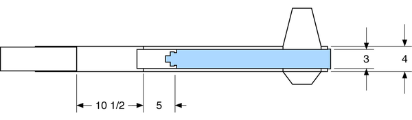
Figure 13-9. Dimensions for the parachute bay in the booster.
The desired mass of 4FG black powder for a chamber this size is:


Since the mass of black powder in grams is very close to its volume in cubic centimeters, you can measure this as either 1.3 grams or 1.3 cubic centimeters.
Figure 13-10 shows the relevant dimensions for the forward parachute bay. Approximating the nose cone as a cone rather than an ogive, the calculations work out like this:


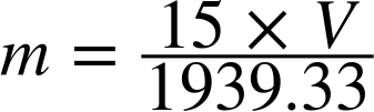

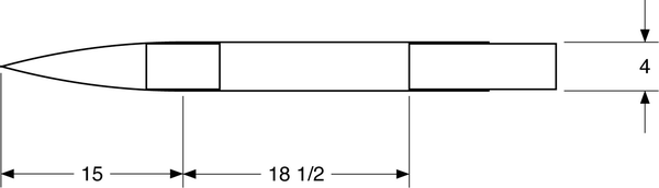
Figure 13-10. Dimensions for the forward parachute bay.
There are lots of ways to pack the charges. Figure 13-11 shows my favorite, with the black powder and igniter stuffed into the finger of a disposable glove. A layer of tape under the charges protects the bulkhead, while a layer of tape over the charges will hold the charges in place during flight. Of course, there is a primary and backup charge, one attached to each flight computer.

Figure 13-11. Use the finger from a disposable glove to hold the black powder, and tape to protect surfaces and secure the charges.
Doing the math or using a table is an important first step, but you must, of course, do a ground test to verify the charges are the right size. See “Testing Recovery Charges” for thoughts about the ground test.
Selecting Parachutes
The completed rocket, with motor, weighs in at 321 ounces, or a tad over 20 pounds. A full 6 pounds of that weight is rocket fuel, so the weight at recovery drops to 14 pounds. Checking Table 9-1, we see that the drogue parachute should be in the 24- to 36-inch-diameter range. Many fliers don’t use a drogue parachute at all on a rocket like Ganymede, since merely popping the rocket apart into two roughly equal-size tethered tubes causes the rocket to become unstable, increasing the drag significantly. I think that puts too much strain on the main parachute, so I did use a drogue parachute, but I used that reasoning to choose the smaller, 24-inch size.
Table 9-1 doesn’t show parachutes larger than 60 inches in diameter, and that’s not big enough for a main parachute on a 224-ounce rocket. We could do the calculations to find the correct parachute size, but it turns out that it is hard to find a flat parachute larger than 60 inches in diameter, so the calculations don’t help much. There are a lot of possibilities out there, but I opted for the Sky Angle 60” parachute, which has a coefficient of drag of 1.89. The coefficient of drag is based on the circular center of the parachute, which is a 60-inch circle. That works out to an area of 1.82 square meters. Converting the 14-pound weight of the rocket to its metric equivalent, we get 62.2 newtons. That gives all of the values we need to find the velocity from the equation given in “Parachute Aerodynamics”:
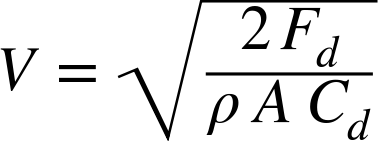
Plugging in the values, we get:

This is right in the middle of the accepted range for speed. Combined with the drogue parachute and the drag from the rocket itself, this will work just fine.
Flying Ganymede
Despite its size, flying Ganymede is really not very different than flying Phobos as a dual-deploy rocket. My own flight was made in Black Rock, Nevada, at BALLS 23. The launch altitude was about 3,600 feet above sea level, and the rocket itself flew either 13,858 feet or 12,577 feet above ground level, depending on which computer you believe. Based on simulations, I suspect the 13,858-foot altitude is closer to the correct mark. That puts the rocket about 17,000 feet above sea level. While that is below the jet stream, it is still high enough that the winds aloft can be very, very different from what you see on the ground. One additional item for your flight preparation is to check the Aviation Weather Center website. This site gives the wind speed and direction at various altitudes. One of our club members did not take this into account on a flight, and also mistakenly ejected the main parachute at altitude. The rocket was found the next day by radio, several miles from the launch point.
The Motor
Other than sheer size, there really isn’t much difference between assembling the motors you’ve already used and assembling a Level 3 motor. Depending on what you have already tried, the one new aspect might be some extra O-rings that go between the fuel grains to make sure there is a separation between them, giving a nice, even burn. The details can also vary from one motor to the next, so we won’t go over motor assembly here. Instead, follow the directions that came with your motor.
Since this is for your Level 3 flight, one of the people on your certification team will want to watch you assemble the motor (see Figure 13-12). It does take some time and a nice clean work area, though. The approach I recommend is to get together with your certifying team a day or two before the flight to assemble the motor. This is a good time for you to ask any last-minute questions, and for them to check your preparations, possibly saving you from an error.
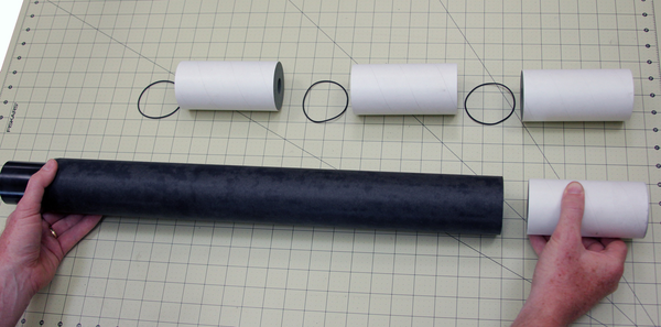
Figure 13-12. Assemble the motor a day or two before the flight, with your certifying team.
There are also some very real differences in the igniters used with a large motor. The most striking is that the motor probably will not come with one. You will need to order a large igniter, and they can be difficult to find. As I write this, Wildman Rocketry sells a package of three igniters with the SKU BIG-UNS-LG-LIGHTERS that will work, but sources change rapidly. Check with your club members for good igniter sources; they may even be able to sell one to you.
The igniter will also be quite long, and it is very difficult to stuff it all the way up into a 24”-long motor. The igniter itself should be taped to a 1/8”-diameter wooden dowel or stick. Use this stick to shove the igniter into place, securing it at the base of the rocket (see Figure 13-13). It may seem odd to leave a sturdy wooden stick inside the motor when it is lit, but the motor will have no problem burning or ejecting the stick as it comes up to full power.

Figure 13-13. Use a 1/8” wooden dowel to insert the igniter into the motor.
Warning
The dowel used to hold the igniter in place must be thin compared to the size of the opening in the nozzle. The 1/8”-diameter dowel shown here works fine with the AeroTech M1297W. If you are unsure about the rod size, check with more experienced fliers who have used the specific motor you intend to fly.
Checklists
The bigger the rocket, the more important checklists become. In fact, you saw a checklist of checklists back in “Checklists”! Here are the standard prelaunch and launch checklists for Ganymede. You may need to modify them slightly based on your location or design changes, but they are a good start.