LENSLESS MICROSCOPE
A webcam’s image chip is an ultrafine shadow-imaging stage.
Photography by Sam Murphy (this page, A, B) and Tom Zimmerman (C, D, I)
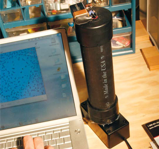
Imager chip from a 5MP camera mounted in a black box captures microscopic shadows of rotifer plankton.
Behind the lens of a webcam is an imager chip with thousands of tiny light sensors, each about 1/10 the diameter of a human hair. If you replace the lens with an LED light source, and place tiny objects on the imager chip, shadows will project onto the sensor, creating a lensless microscopic image. You can use the webcam’s regular software to save pictures and video, or stream live images to the internet. Or use the imager chip from a security camera to see a colony of live plankton on TV.
1. Remove the imager board from the webcam.
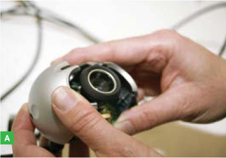
If you’re using a video board camera, go to Step 2. Remove all screws on the web camera case, pry it apart, and remove the imager board (Figure A).
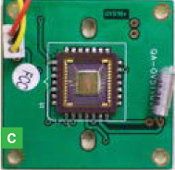
2. Remove the lens.
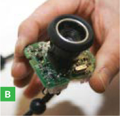
Unscrew the lens holder from the circuit board (Figure B) to reveal the imager chip (Figure C). Don’t touch the protective glass cover; that’s where your specimens are eventually going to go.
3. Prepare the dark box.
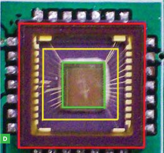
Examine the imager chip. The innermost square (Figure D, green outline) is the light-sensitive image die. The raised square just inside the soldered legs is the ceramic case (red outline). Measure out a third square area between these 2 squares, covering most of the fine gold wires that connect to the image die (yellow square). Pick a drill bit with a diameter close to this width. We’ll be referring to this yellow square later.
Use the selected bit to drill a hole centered in the bottom of the project box. Square the hole with the file (Figure E).
4. Prepare the imager.
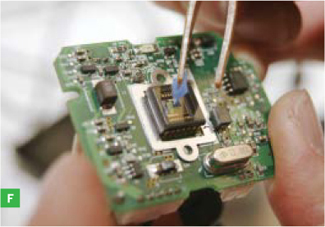
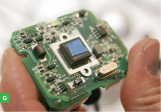
You need to cover the chip’s light-sensitive area with tape to protect it from silicone sealant. If the tape is too small, the image will be obscured by sealant. If the tape is too big, there won’t be enough glass to glue to the dark box. Cut a piece of blue tape the size of the yellow square (Figure F) and center it over the imager chip (Figure G). As you cut and place the tape, hold it with tweezers so that you don’t get finger oil on it.
5. Make a spacer.
If the imager chip is the tallest component on its circuit board, go to Step 6. But if other components stick up farther from the board’s surface than the imager chip, you need a spacer.
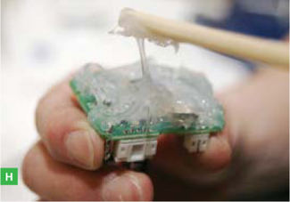
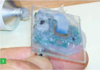
In the center of the 3" x 3" piece of plastic, drill and file a square hole the size of the yellow square. Drill and file holes to fit over the contours of all tall components, so that the square hole will lie flat over the chip. Place a big wad of aquarium silicone sealant on the entire imager board; more is better (Figure H). Press the plastic spacer down onto the imager chip, centering the blue tape in the plastic’s square hole (Figure I). Remove any extruded sealant for a better view. Alignment is critical, so do a careful job. Let the sealant set overnight.
Photography by Sam Murphy
6. Glue the imager into the dark box.
If you made a spacer (Step 5), squeeze a big wad of silicone sealant all over the spacer. Otherwise, squeeze it all over the board and imager chip (Figure H). More is better.
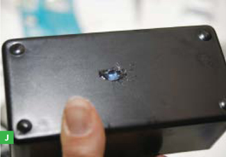
Place the circuit board in the bottom of the box, pressing it against the square hole and causing sealant to extrude out. Center the blue tape within the square hole (Figure J), removing any extruded sealant for a better view. Alignment is critical; the entire blue square must be aligned and centered within the box’s square hole. The sealant will create a gasket to prevent water from reaching the circuit board. Let the sealant set overnight.
Find the imager’s glass cover with the point of the hobby knife blade, and drag the blade around the perimeter of the square hole, cutting through the sealant and blue tape. Use tweezers to pull off the sealant and blue tape, revealing a pristine glass surface.
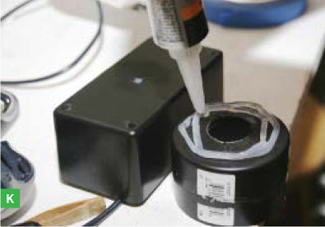
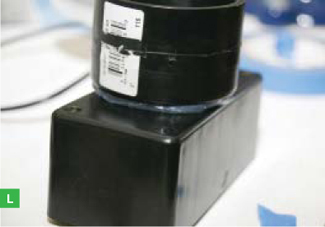
7. Prepare the end caps.
Drill a 1" hole in the middle of one of the PVC caps, then center it over the square hole in the dark box. Glue it down using silicone sealant (Figures K, L, M).

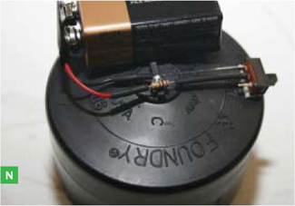
Drill a 1/8" hole in the center of the other PVC cap. Solder the LED, battery snap, resistor, and switch in series. If the LED doesn’t light, reverse the battery leads. Press the LED into the 1/8" hole and hot-glue it and the other components to the top of the cap (Figure N).
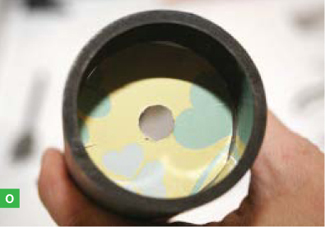
Cut the cardboard into a 2" circle, drill a ½" hole in the center, and cut 10 or so radial lines ¼" inward from the circumference, spaced out approximately evenly, to make tabs that will fold back as you push the disk into the tube. Shove the disk 1" deep and flat into the bottom end of the PVC tube (Figure O). The inside of the tube is shiny and could cause reflections that would blur the image, but the hole in the cardboard only lets light coming directly from the LED reach the objects on the imager. This ensures that the shadows cast on the image sensing area are sharp.
8. Behold!
Put some salt or other small objects on the imager chip’s glass cover, assemble the microscope with the LED end cap on top (Figure P), turn on the LED, and behold the microscopic world. Since we didn’t touch the web camera’s electronics, all of its software will work.
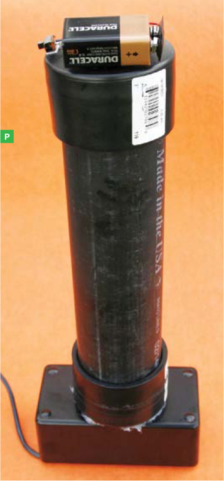
You can put solids (sand, salt, sugar), liquids (plankton samples, murky outdoor water), and objects (moth, fly) directly on the imager’s glass cover. As with a regular optical microscope, the image comes from light shining through the subject. The magnification of the lensless microscope is the ratio of the monitor width to the imager sensor width (about 7mm).
Use a dry cotton swab to clean liquids off the glass. Use a straw to blow solids off (close your eyes!), or clean the glass with an alcohol-soaked swab.
Note that you’ll get false colors due to imperfections in the imager’s color filters and camera software. Try different-colored LEDs for interesting effects. If you’re ambitious, you can hack a megapixel camera (Figure 5) in the same way and obtain higher resolutions — potentially much higher, depending on the camera.
![]() See a video of rotifer plankton taken by the lensless microscope at makezine.com/go/plankton.
See a video of rotifer plankton taken by the lensless microscope at makezine.com/go/plankton.
Tom Zimmerman is an inventor, educator, and researcher at the IBM Almaden Research Center who loves gadgets, LEDs, synthesizers, and hooking people up to computers.

An old CD makes a great temporary cover for an open can of paint, quart-size or smaller. Just cut it so it can slip over your paintbrush, and it will keep the brush suspended in the paint or solvent.
—Frank Joy
Photos captured by the lensless microscope in various configurations.
Photography by Tom Zimmerman
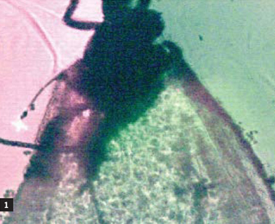
1. Moth, VGA webcam imager, red LED.
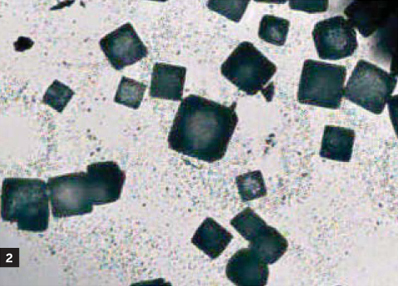
2. Salt crystals, VGA webcam imager, white LED.
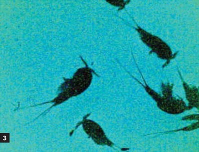
3. Copepod plankton, VGA webcam imager, blue LED.
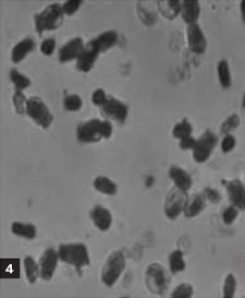
4. Rotifer plankton, CCD black-and-white video imager, blue LED.

5. Portion of image of rotifer plankton, 5 megapixel imager, blue LED.