TIP: Here’s something you may not realize:
Most 3D CAD packages can import a STEP file
and let you edit it, scale it, and then merge it with
your own design. This can be a valuable shortcut
from having to create a joint as a new feature
with explicit dimensions for an extrusion. You
can review the dimensions of the tongue-and-
groove joint pieces by using the STEP file with the
dimensioning features of your CAD software.
The Printables site also has project files for the
ventilated case top mentioned above.
Plan to secure and protect the Pi and camera
such that the camera has a fixed position, or is
easily moved to a known position, when you’re
observing the app display. For example, a camera
bracket could be fastened to a window frame
using wood screws.
SOFTWARE SETUP
Once your Pi system is up and running Raspberry
Pi OS, and on the network, you can install the
speed trap software. Python3 is likely already
installed, and support for the camera and for an
older but adequate version of Open CV (3.2.0)
exists in the default software repositories. So this
sequence of commands is likely all that’s needed:
sudo apt update
sudo apt-get install python3-opencv
python3-picamera
Download the project code file, piMotion.py, from
the project page at makezine.com/go/pi-cam-
speed-trap. Then you can run it at a command
prompt of the ssh -X login window:
pi@raspberrypi:~/pycode $ ./piMotion.
py
D E
3D printed a camera case with a built-in hood
(Figure
C
). You can download this case design,
and the brackets that support it on a wooden
slat of the window blinds, from printables.com/
model/172019. The lens hood should be printed
in black filament or painted matte black to reduce
light reflection. The brackets feature button heads
spaced 40mm apart to support the Raspberry Pi
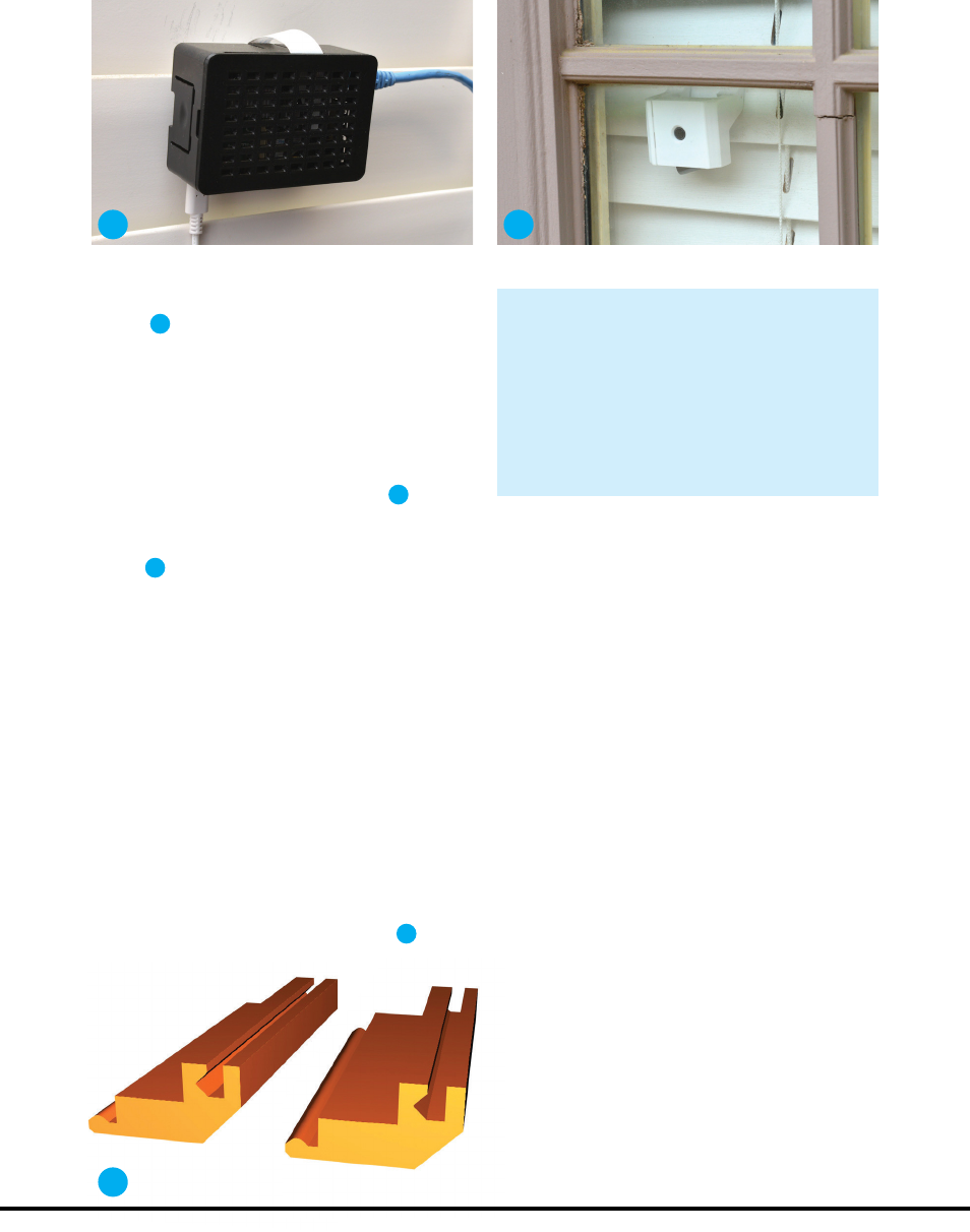
case on the shade interior side (Figure
D
).
A non-shaded camera case that rests on
wood blinds using the same brackets is seen in
Figure
E
; you can download the 3D files from
printables.com/model/107623.
NO-FASTENER CAMERA CASE
We are makers, so let’s talk about the interlocking
tongue-and-groove joints that slide into place on
the camera cases. An experienced designer
recognizes up front that several iterations of
varying the dimensions, printing the items, and
testing the fit may be needed to settle on the final
dimensions. To economize on time and materials,
a small test piece is designed and two of them are
printed for test fitting, instead of the full-size
items. So I’ve included a STEP CAD file and 3MF
print file for the tongue-and-groove joint in the
shaded case downloadable files (Figure
F
).
Pi case mounted on interior of window blind. Plain camera case on window shade.
F
79
make.co
M83_076-83_PiCamSpeedTrap_F1.indd 79M83_076-83_PiCamSpeedTrap_F1.indd 79 10/10/22 4:16 PM10/10/22 4:16 PM
..................Content has been hidden....................
You can't read the all page of ebook, please click here login for view all page.
