
Introduction
Much professional photography is carried out using large-format cameras (Figure 10.1). These offer high image quality and versatility due to modular design and camera movements used for control of focus, distribution of image sharpness and the shape of the image. A direct-viewing focusing screen is essential.

Figure 10.1Types of large format cameras. (a) Folding baseboard camera with coupled rangefinder and optical viewfinder. (b) View camera or field camera of baseboard type. (c) Monorail camera with L-shaped standards to take the lens panel and focusing screen. (d) A monorail camera of simple construction with U-shaped standards
Such cameras are called view cameras or technical cameras. They may be of monorail or folding baseboard construction, the former giving unsurpassed versatility. The monorail design uses the principle of an optical bench carrying the front and rear standards, which in turn carry the lens panel (Figure 10.2) and film holder respectively, and which are connected by a flexible or pleated bellows. The standards may be of U or L shape, and the various movements usually have click-set ‘neutral’ positions and are lockable in other positions. Rotational movements are usually calibrated in degrees and translational (‘shift’) movements in millimetres. A rotational movement may be about an axis either through the standard, termed centre tilt, or about an axis located near the monorail, termed base tilt; or the axis may be movable to various positions. Each has advantages and limitations. Some of the various camera movements may also be found in medium format cameras and perspective control (PC) lenses.

Figure 10.2A monorail camera showing the lens panel and calibrated controls for movements of the front standard
The various possible movements in a view camera are shown in Figure 10.3, and are detailed in Table 10.1. These movements are the ‘degrees of freedom’ of the imaging system.
Table 10.1 A summary of camera movements using the notation of Figure 10.1


Figure 10.3Monorail camera with its movements neutral. The optical axis and the camera axis are coincident in this neutral position
The first group of movements are those of lateral displacement or translation (‘shifts’) along mutually orthogonal XYZ axes, which are centred ideally either at the rear nodal point of the lens (so that the X axis is by convention the optical axis when horizontal), or at the image principal point P where the optical axis intersects the film plane orthogonally at the centre of the format (Figure 10.3). For the purpose of this chapter the rear X axis is called the camera axis and the front X axis the lens axis. Initially a view camera may be set up with both lens and camera axes coincident, colinear and horizontal, the so-called neutral position, after which camera movements can be applied, including tilting the combined axes from their horizontal orientation.
Movements along the X axis give front focus or rear focus with reference to the lens panel and film holder respectively. The former movement alters sharp focus and magnification together, the latter alters focus at a fixed magnification. Alternatively, both standards may be moved together at a fixed separation to obtain sharp focus on the subject by moving the whole camera. Front and rear linear movements along the Y (transverse) and Z (vertical) axes are useful to centre the subject on the film format without tiresome small adjustments of the camera on its stand. These ‘rising’, ‘falling’ and ‘cross’ movements are also useful in retaining parallel lines or features in the image where a centralized viewpoint is not possible. The film plane needs to be kept vertical or parallel to the subject (Figure 10.4).

Figure 10.4Use of translational movements. (a) An enforced oblique view of subject S, due to obstruction K. Square and circular subjects are imaged as trapezoidal and elliptical respectively. L camera lens; F film plane. (b) Ideal square-on view without movements. (c) An oblique view using cross-front movements to simulate a square-on view. All views are from above
An important consideration is the covering power of the lens, which determines the permissible extent of translational movements.
Rotational Movements
In theory, both the lens and the film plane may be rotated about each of the XYZ axes, these three rotational and three translational (displacement) movements giving a total of six degrees of freedom for each. In practice the lens is not rotated about its X axis (optical axis) as it is axially symmetrical. With a helical focusing mount, the focusing action gives X-translation and rotation combined. An eccentric lens panel allows translation movements as a rotation of the optical axis about the camera axis. The film plane may have X-rotation in the form of a rotating back which revolves the film-holder 90° continuously from a vertical to a horizontal position, or even through 360°. The important rotations are those about the Y and Z axes, referred to as tilt and swing respectively. Front and rear tilt and swing may be used either individually or in combination, or in conjunction with displacement movements. For some purposes, front or rear tilt or swing may be used interchangeably; but in general those of the lens are used to control the distribution of sharpness in the image, and those of the film holder to determine the shape or ‘perspective’ of the image (details are given below). The allowable amount of lens movement is dependent on the covering power of the lens used.
Lens Covering Power
The covering power of a lens is the diameter of the circle of good definition in the focal plane. This value is less than or (rarely) equal to that of the circle of illumination from the lens. Covering power is a minimum at maximum aperture and infinity focus, but increases as the lens is progressively stopped down, or focused closer (Figure 10.5).

Figure 10.5Lens covering power and camera movements: the format x ´ y related to image circles of various radii R. Key: R1 format semi-diagonal, as covered by a large aperture or telephoto lens at infinity focus; R2 lens with extra covering power of 70 degrees, infinity focus, full aperture; R3 lens used at f/22; R4 lens used at m = 1, Y possible vertical shift, X possible horizontal shift; √(X2 + Y2) is the maximum combined displacement movement
A lens designed for use with camera movements usually has extra covering power to give a circle of good definition significantly larger than the format in use (Figure 10.6). The film area remains within the circle of good definition when translational movements are used or when the lens is tilted or swung. It is common practice to use as a standard lens for a given format which can accommodate some 50 degrees, one with a covering power corresponding to a field of view (FOV) of some 70 to 80 degrees, hence allowing some 10 to 15 degrees of lens rotation or tilt. Wide-angle lenses may have less additional covering power. Where the FOV on the format is not of prime concern but extensive movements are needed, then a ‘long-focus wide-angle’ technique may be used. This means that a wide-angle or standard lens for a larger format is used, so that the extra covering power for that format gives exceptional covering power for the smaller format. Thus a 210 mm wide-angle lens for an 8 × 10 inch format used with a 4 × 5 inch format offers a slightly long-focus lens with a circle of good definition of diameter some 500 mm relative to the format diagonal of 164 mm.

Figure 10.6Image circle and lens covering power. A 150 mm lens for a 4 ´ 5 inch format (outlined) gives an image circle larger than the format, allowing extensive camera movements to be used. The lens was used on a 8 ´ 10 format camera to produce this image. Lack of covering power or too much movement used will result in cut-off by vignetting
The extent of the translational movements may be limited not only by covering power available, but also by the type of film used. This is because the exposure latitude of the film has to allow for the cos4 θ factor in the decrease of image illumination at the edge. At extremes, one side of the film format may be on axis, the other side at the image periphery. Figure 10.7 shows the situation with a lens of focal length f allowing a displacement of up to 0.5f within an image circle of diameter 2f. The natural vignetting gives illumination values and losses as detailed in Table 10.2. Given a change in exposure level of not more than 0.5 EV across the format, then a FOV of 70 degrees for a standard lens, allowing a maximum displacement movement of 0.2f, is a reasonable limit for infinity focus. Individual lenses need to be tested for their capabilities.
Table 10.2 Exposure variation limits to displacement movements
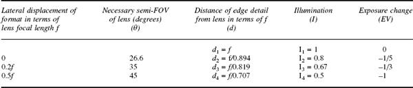

Figure 10.7Displacement movements and image illumination. Geometry of image formation at infinity focus for a standard lens with normal (θ1), extra (θ2) and exceptional (θ3) covering power. F is the film format. (See also Table 10.2)
Control of Image Sharpness
Image sharpness in a photographic record is usually controlled by suitable choice of focused distance, lens aperture and focal length to ensure the necessary depth of field. Large-format cameras use lenses of long focal length; and even with the increase in diameter of the acceptable circle of confusion and the small apertures available, depth of field may be inadequate, especially for an extended subject inclined to the optical axis. Figure 10.8 shows the geometry of such a situation, with the lens focused on a subject point on axis, and near and far subject points focused behind and in front of the film plane respectively, giving large circles of confusion and consequent out-of-focus images on the film. It is evident that rotation of the film plane to coincide with the other foci will give a sharp image overall. It may be less obvious that a similar effect can be produced by keeping the film plane static and instead rotating the lens. Theoretically the two solutions are equivalent, and lead to Scheimpflug’s rule that an inclined subject plane is rendered sharp when the plane of the subject, the rear nodal (principal) plane of the lens and the film plane or photoplane, all extended into space as necessary, meet in a single line. As a proof of this, consider Figure 10.9, which shows the subject plane S, rear nodal plane L and film plane F extended to meet in a common line R. If the lens conjugate equation is satisfied for all points on plane S, then all of the plane will be in focus.

Figure 10.8Rotational movements and Scheimpflug’s rule. Points A, B and C on subject plane S give image points a, b and c and circles of confusion K on film plane F. Rotating F through angle p to intersect with S and lens plane L at R1 gives sharp focus and satisfies Scheimpflug’s rule. But leaving F and instead rotating L through angle q to give intersection at R2 will also give overall sharp focus on S

Figure 10.9Derivation of Scheimpflug’s rule
For a point A at infinity and a point B on S whose image points are a and b respectively, both rays Aa and Bb pass through the optical centre O. Let Aa be parallel to BR. Construct perpendiculars from B, b and a to the plane L, so that the distances aQ, BD and bC represent f, u and v in turn. Then

From similar triangles baO and bRB,

Substituting

but since ab + Ra = Rb, then the quantity in brackets is unity. So the relationship 1/u + 1/v = 1/f holds true for the condition that the three planes meet in a common line.
The Scheimpflug geometry is usually set up by eye, and fine-tuned using the focusing screen; but it is possible to arrive at optimum settings by use of special calculators or calibrations on the lens movement controls. Special enlargers called rectifying enlargers, which are equipped with movements, were once used to correct for the effects of ‘tilt’ in aerial photographs. Mechanical linkages were used to retain automatic setting of the Scheimpflug relationships as well as autofocus.
Limits to Lens Tilt
When camera movements, and in particular lens tilt movements, are used to control image sharpness according to the rules given above, the optical axis of the lens will not in general pass through the centre of the film frame. This means that extra covering power will almost always be needed. A lens with a useful angle of field of 70 degrees, used as a standard lens for a format giving 52 degrees FOV, allows a tilt of no more than about 15 degrees (Figure 10.10), bearing in mind the limitations imposed by cos4 θ fall-off. The limits are increased a little for close-up work, and with the use of small apertures.

Figure 10.10Limits to front movements. A standard lens L set at infinity focus with FOV 70 degrees covers a format with a dimension x to allow a maximum lateral displacement of X. A maximum tilt of φ is possible, where φ = (35–26) = 9 degrees.
In theory, the camera back may be swung to almost any extent, provided that the format remains within the cone of illumination from the lens. In practice there are two limitations, the variations in image illumination and in image shape. The limit to rear tilt movements, and the associated exposure variation across the format, is shown in Figure 10.11. It can be seen that a tilt of no more than 15 degrees results in an illuminance ratio of some 0.6 (approximately 0.5 EV) at the rear and far edges of the tilted film plane. The change in image shape with application of rear tilt is even more important. There is a change in magnification m as image conjugate v varies with tilt, while subject conjugate u is unaltered in the relationship m = v/u.

Figure 10.11Limits to rear rotational movements. With lens L set to infinity focus, d1 = f. Film plane F is swung through angle ω. To a first approximation, d3 = d1 + x and d4 = d1−x. For a typical value of ω of 15 degrees, d3 = 1.13f and d4 = 0.87f. So image illumination ratio I3/I4 is (0.87)2/(1.13)2 = 0.6
The choice of a lens and of a camera with an appropriate range of movements should be considered on the grounds of optical limitations.
In practice, a combination of front and rear tilts may be used to obtain the necessary sharpness, if the subject allows for some distortion. Tilt in an opposite direction may be used to reduce the zone of sharpness for a specific purpose. Tilts are used in conjunction with the aperture setting to obtain a volume of sharply rendered subject space of wedge shape which is judiciously positioned to encompass all of the subject matter that is required to be in focus (see Figure 10.12). Careful use of rotational movements allows minimal use of the iris diaphragm, so allowing a lens to be used at larger apertures, giving better optical performance and allowing shorter exposure times and reduced lighting levels. The main limitation on the use of combined swing and tilt movements is that of mechanical design and the fact that the image framing shifts when movements are used. Some camera designs use a ‘segment tilt’ or ‘radial tilt’ of the standards which avoids this problem by allowing the rotational axis to be positioned precisely in the film plane and to correspond to the part of the subject focused upon (Figure 10.13).

Figure 10.12Depth of field and camera movements. The inclined subject S is not fully within the depth of field T1 until lens is rotated through angle φ to satisfy Scheimpflug’s rule, locating S within depth-of-field zone T2

Figure 10.13Tilts and mechanical designs. C is the centre of rotation, which does not usually coincide with the rear nodal point of the lens or the film plane. The segment or radial tilt is the exception. C may be located elsewhere, denoted by R
The (theoretically) simple camera movements of displacement and rotation may only be realizable in some camera designs by the simultaneous use of several movements to give the equivalent of one simple movement (Figure 10.14).

Figure 10.14Equivalent movements. Dependent on mechanical design limitations, a particular camera movement may be given in various ways, as shown here for rising front, using base and centre tilts on front and rear
The efficient use of swing and tilt movements is hampered in practice by uncertainty concerning the exact position of the axis of rotation. Lenses mounted in a panel seldom have the rear nodal plane corresponding to the axis of rotation. In the case of telephoto lenses, the rear nodal plane is in front of the lens barrel itself and any angular movement needs to be greater than might be expected. However, such lens designs seldom have extra covering power, and do not lend themselves to use of camera movements. Centre tilt would appear to be advantageous, as little or no refocusing is required after use, in contrast to the application of base tilt, but film holders can be inserted unobstructed with the latter design. Some cameras provide both base and centre tilts.
Control of Image Shape
A view camera with all movements at neutral, imaging a planar subject perpendicular to the optical axis, will give (within the usual practical limits) an undistorted image which is a true perspective rendering of the subject. If the film plane is swung (or tilted) and the lens is also swung to satisfy the Scheimpflug condition, then the image shape will also alter (Figure 10.15). Lines formerly perpendicular to the rotation axis will now converge to a ‘vanishing point’ of perspective. This is due to the alteration in the image conjugate v while the subject conjugate u remains constant, resulting in a change in magnification. This change in image shape can be used to produce deliberate changes in perspective, for example to make lines inclined to the film plane parallel, and to make parallel lines converge towards a vanishing point. By making the film plane more parallel or less parallel to the plane of the subject, linear detail can be made to converge respectively to a lesser or greater extent. The result in turn is a ‘flattening’ or ‘steepening’ of perspective (Figure 10.16), but of course the viewpoint due to the lens position does not change. The term ‘perspective control’ is often used to describe this type of manipulation of the optical image.

Figure 10.15Effect of film plane rotation on image shape. (a) Rotation of film plane F through angle ω alters v to v1 and v2 and changes magnifications. (b) Appearance of subject with all movements neutral. (c) With rear swing about Z axis to give vanishing point V1. (d) With combined rear swing and tilt about Z and Y axes respectively to give vanishing points V1 and V2

Figure 10.16Perspective control by alteration of image shape. As an example, an oblique view of a cube with progressive swing of the film plane to be parallel to the front face gives image shape and vanishing points as shown from (a) to (c)
A common application of such perspective control is in the photography of buildings, where an oblique viewpoint with a camera in neutral mode gives a true perspective rendering but with unacceptable converging verticals in the picture. The preferred ‘drawing’, (i.e. with the vertical lines remaining parallel) is obtained by restoring the film plane to the vertical. In practice the photographer usually uses the rising front (Figure 10.17).

Figure 10.17The use of rising front. This is in effect a rear tilt movement to remove the convergence of vertical lines. (a) Conventional oblique view. (b) Film back parallel to vertical subject
An anomalous effect may sometimes arise in such ‘corrected’ photographic images: it is a purely subjective keystone effect. Although the verticals in the print are indeed parallel, they nevertheless appear to be diverging, for example at the top of a building, resulting in a top-heavy appearance. The reverse effect arises when a high oblique viewpoint is used with drop front to retain parallel linear features: the subject then appears wider at the base. The best way of avoiding this is to apply somewhat less of the camera movements than would be suggested by theory. The cause of this anomalous effect is not simply an optical illusion: it is that the outermost part of the field of view actually becomes elongated because of geometrical distortion in the image when it is subjected to this type of ‘correction’.
Most small- and medium-format cameras lack movements other than focusing; but lenses are available as alternatives which incorporate a limited range of translational and rotational movement as part of the construction of the lens barrel and mount (Figure 10.18). They are called perspective-control (PC) or ‘shift’ lenses. They are of semi-wide-angle or wide-angle types with the necessary extra covering power to allow up to 11 mm of lateral displacement or 10 degrees of tilt relative to the 24 mm side of the 24 × 36 mm format. Usually the lens can be displaced in only one direction by mechanical movement, but by rotating the whole lens the direction of the shift axis can be changed, to allow the equivalent of rising and drop front or cross front. Even with full movement applied, hand-held exposures are possible, provided moderate apertures are used. Although such lenses cannot give a 35 mm camera the full perspective control available with a view camera equipped with an extensive range of movements, they do make it possible to produce satisfactory record photographs of (for example) architecture, under circumstances where large-format equipment would be unacceptably cumbersome. One manufacturer (Canon) offers a range of tilt and shift (TS) lenses with focal lengths of 24 mm, 45 mm and 90 mm to deal with a variety of subjects. Such lenses are useful with digital cameras, especially for still-life studio subjects with full correction and control of depth of field.

Figure 10.18A perspective control lens for the 24 × 36 mm format. The control for the lateral shift movement is at the left and the shift is calibrated in millimetres
PC lenses have complex retrofocus optical designs but have almost no automation of operating functions other than a simple preset aperture diaphragm. There is no autofocus and manual metering is best done stopped down to the selected aperture. PC lenses are easily adapted to a variety of other cameras for wide-angle and panoramic work. The usable image circle is some 56 mm in diameter compared with the 43 mm of other lenses for the 24 × 36 mm format.
Slide projectors may be fitted with PC projection lenses to provide a lateral shift of the projected image to coincide accurately with that of an adjacent projector with no loss of sharpness or keystone distortion to a trapezoidal shape. This accurate overlap of images is essential in multi-projector installations for multi-media presentations.
In the absence of camera movements or a PC lens, necessary corrections to inadvertent tilt effects in an image can be corrected by digital image processing techniques. The image is converted to digital form and then the necessary geometrical distortion is applied by trial and error to give the ‘corrected’ shape. This is analogous to using movements in an enlarger to change image shape, and in particular, both are frequently used to correct for converging verticals.
Shift Cameras
Arguably, the camera movement most frequently used outdoors is rising front, and for studio work it is drop front, both providing correction of vertical lines from a low or a high viewpoint respectively. This movement is provided in a range of shift cameras (Figure 10.19) in both medium and large formats, as well as to a lesser extent in some panoramic cameras. Shift cameras are greatly simplified versions of wide-angle cameras to provide very accurate register of film plane to the lens and precisely controllable amounts of shift. Such cameras can make full and efficient use of a new generation of extreme wide-angle rectilinear lenses which have great covering power and field of view of typically 100 degrees. In use it is essential that such cameras are equipped with accurate spirit levels to ensure that the film plane is truly vertical, as only a small error can cause unwanted geometrical distortion of the image due to the very wide angle covered.

Figure 10.19A shift camera. A much simplified construction is used with a shallow rigid body and helical focusing on the lens barrel. A single control sets the amount of shift
It is possible to use an extension bellows fitted with movements to provide a form of shift camera. The lens used has to be of longer focal length than the standard one to permit focusing on infinity with the added extension of the bellows between lens and camera body. Wide-angle work is not usually possible. One manufacturer (Hasselblad) can supply an alternative camera body that is essentially a precision extension bellows that can take a lens, even a wide-angle type, at one end and a focusing screen or film magazine at the other.
Bibliography
Harris, M. (1998) Professional Architectural Photography. Focal Press, Oxford.
Harris, M. (1998) Professional Interior Photography. Focal Press, Oxford.
Ray, S. (1994) Applied Photographic Optics, 2nd edn. Focal Press, Oxford.
Stroebel, L. (1993) View Camera Technique, 6th edn. Focal Press, Stoneham, MA.