
Chapter 3: Setting Up and Using AutoCAD’s Drafting Tools
Chapters 1 and 2 covered the basic information you need to understand the workings of AutoCAD. Now you’ll put this knowledge to work. In this architectural tutorial, which begins now and continues through Chapter 15, you’ll draw an apartment building composed of studios. The tutorial illustrates how to use AutoCAD commands and gives you a solid understanding of the basic AutoCAD package. With these fundamentals, you can use AutoCAD to its fullest potential regardless of the kinds of drawings you intend to create or the enhancement products you may use in the future.
In this chapter, you’ll start drawing an apartment’s bathroom fixtures. In the process, you’ll learn how to use AutoCAD’s basic tools. You’ll also be introduced to the concept of drawing scale and how the size of what you draw is translated into a paper sheet size.
In this chapter, you’ll learn to do the following:
- Set up a work area
- Explore the drawing process
- Plan and lay out a drawing
- Use the AutoCAD modes as drafting tools
Get Additional Help on the DVD
The companion DVD offers four video tutorials that give you an overview of the main topics of this chapter. The video entitled “Object Snaps” covers the discussion of the Object Snaps found in the later part of this chapter. The video entitled “Setting Up a Drawing” touches on some of the material in “Setting Up a Work Area.” “Exploring the Drawing Process” covers the material in the section of the same name. And finally, “Object Snap Tracking” covers the material in “Aligning Objects by Using Object Snap Tracking.
Before beginning most drawings, you should set up your work area. To do this, determine the measurement system, the drawing sheet size, and the scale you want to use. The default work area is roughly 16˝ × 9˝ at full scale, given a decimal measurement system in which 1 unit equals 1 inch. Metric users will find that the default area is roughly 550 mm × 300 mm, in which 1 unit equals 1 mm. If these are appropriate settings for your drawing, you don’t have to do any setting up. It’s more likely, however, that you’ll make drawings of various sizes and scales. For example, you might want to create a drawing in a measurement system in which you can specify feet, inches, and fractions of inches at 1˝ = 1´ scale and print the drawing on an 8½˝-×-11˝ sheet of paper.
In this section, you’ll learn how to set up a drawing exactly the way you want.
Specifying Units
You’ll start by creating a new file called Bath. Then you’ll set up the unit style.
Use these steps to create the file:
1. If you haven’t done so already, start AutoCAD. If AutoCAD is already running, click the New tool from the Quick Access toolbar.
2. In the Select Template dialog box, select acad.dwt and click Open. Metric users should select acadiso.dwt and then click Open.
3. Type Z↵ A↵ or click Zoom All from the Zoom flyout in the navigation bar.
4. Choose Save As from the Application menu.
5. In the Save Drawing As dialog box, enter Bath for the filename.
6. Check to make sure you’re saving the drawing in the My Documents folder or in the folder where you’ve chosen to store your exercise files, and then click Save.
Using the Imperial and Metric Examples
Many of the exercises in this chapter are shown in both the metric and Imperial measurement systems. Be sure that if you start with the Imperial system, you continue with it throughout this book.
The metric settings described in this book are only approximations of their Imperial equivalents. For example, the drawing scale for the metric example is 1:10, which is close to the 1˝ = 1´-0˝ scale used in the Imperial example. In the grid example, you’re asked to use a 30-unit grid, which is close to the 1´ grid of the Imperial example. Dimensions of objects are similar, but not exact. For example, the Imperial version of the tub measures 2´-8˝ × 5´-0˝ and the metric version of the tub is 81 cm × 152 cm. The actual metric equivalent of 2´-8˝ × 5´-0˝ is 81.28 cm × 152.4 cm. Measurements in the tub example are rounded to the nearest centimeter.
Metric users should also be aware that AutoCAD uses a period as a decimal point instead of the comma used in most European nations, South Africa, and elsewhere. Commas are used in AutoCAD to separate the X, Y, and Z components of a coordinate.
The next thing you want to tell AutoCAD is the unit style you intend to use. So far, you’ve been using the default, which is a generic decimal unit. This unit can be interpreted as inches, centimeters, feet, kilometers or light years. When it comes time to print your drawing, you can tell AutoCAD how to convert these units into a meaningful scale.
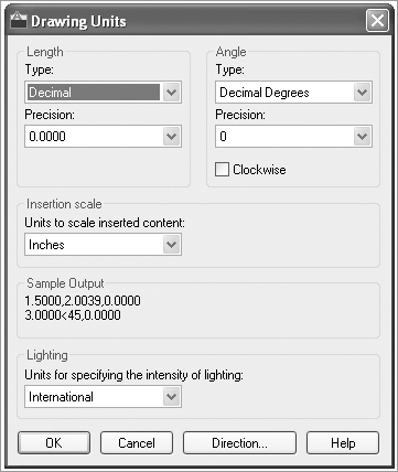
If you are a U.S. user, decimal units typically represent inches. If you want to be able to enter distances in feet, you must change the unit style to a style that accepts feet as input. You’ll do this through the Drawing Units dialog box shown in Figure 3-1.
If you’re a civil engineer, you should know that the Engineering unit style lets you enter feet and decimal feet for distances. For example, the equivalent of 12´-6˝ is 12.5´. If you use the Engineering unit style, you’ll ensure that your drawings conform to the scale of drawings created by your architectural colleagues.
Figure 3-1: The Drawing Units dialog box
Follow these steps to set a unit style:
1. Click Drawing Utilities Units from the Application menu or type Un↵ to open the Drawing Units dialog box.
2. Let’s look at a few of the options available. Click the Type drop-down list in the Length group. Notice the unit styles in the list.
3. Click Architectural. The Sample Output section of the dialog box shows you what the Architectural style looks like in AutoCAD. Metric users should keep this setting as Decimal.
Shortcut to Setting Units
You can also control the Drawing Units settings by using several system variables. To set the unit style, you can type ’lunits↵ at the Command prompt. (The apostrophe lets you enter this command while in the middle of other commands.) At the Enter new value for LUNITS <2>: prompt, enter 4 for Architectural. See Appendix D for other settings.
4. Click the Precision drop-down list just below the Type list. Notice the options available. You can set the smallest unit AutoCAD will display in this drawing. For now, leave this setting at its default value of 0´-0 1⁄16˝. Metric users will keep the setting at 0.0000.
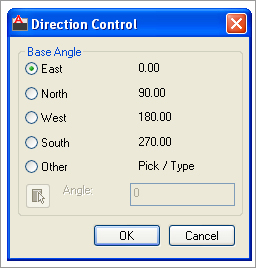
5. Press the Esc key to close the drop-down list, and then click the Direction button at the bottom of the Drawing Units dialog box to open the Direction Control dialog box. The Direction Control dialog box lets you set the direction for the 0° angle. For now, don’t change these settings—you’ll read more about them in a moment.
6. Click the Cancel button.
7. Click the drop-down list in the Insertion Scale group. The list shows various units of measure.
8. Click Inches; if you’re a metric user, choose Centimeters. This option lets you control how AutoCAD translates drawing scales when you import drawings from outside the current drawing. You’ll learn more about this feature in Chapter 29.
9. Click OK in the Drawing Units dialog box to return to the drawing.
If you use the Imperial system of measurement, you selected Architectural measurement units for this tutorial, but your work may require a different unit style. You saw the unit styles available in the Drawing Units dialog box. Table 3-1 shows examples of how the distance 15.5 is entered in each of these styles.
Table 3-1: Measurement systems available in AutoCAD
| Measurement System | AutoCAD’s Display of Measurement |
| Scientific | 1.55E+01 (inches or metric) |
| Decimal | 15.5000 (inches or metric) |
| Engineering | 1´-3.5˝ (input as 1´3.5˝) |
| Architectural | 1´-3½˝ (input as 1´3-½˝) |
| Fractional | 15½˝ (input as 15-½˝) |
In the previous exercise, you needed to change only two settings. Let’s look at the other Drawing Units settings in more detail. As you read, you may want to refer to Figure 3-1.
Fine-Tuning the Measurement System
Most of the time, you’ll be concerned only with the units and angles settings of the Drawing Units dialog box. But as you saw in the preceding exercise, you can control many other settings related to the input and display of units.
Taking Measurements
To measure the distance between two points, click Distance from the Measure flyout on the Home tab’s Utilities panel, or type Di↵, and then click the two points. (Di is the shortcut for entering Dist↵.) If this command doesn’t give you an accurate distance measurement, examine the Precision option in the Drawing Units dialog box. If it’s set too high, the value returned by the Dist command may be rounded to a value greater than your tolerances allow even though the distance is drawn accurately.
The Precision drop-down list in the Length group lets you specify the smallest unit value that you want AutoCAD to display in the status bar and in the prompts. If you choose a measurement system that uses fractions, the Precision list includes fractional units. You can also control this setting with the Luprec system variable.
The Angle group lets you set the style for displaying angles. You have a choice of five angle styles: Decimal Degrees, Degrees/Minutes/Seconds, Grads, Radians, and Surveyor’s Units. In the Angle group’s Precision drop-down list, you can specify the degree of accuracy you want AutoCAD to display for angles. You can also control these settings with the Aunits and Auprec system variables.
You can find out more about system variables on the AutoCAD 2011 Help website. Select the Command Reference option in the left column of the page, and then select the first letter of a system variable name from the System Variable listing.
You can tell AutoCAD which direction is positive, either clockwise or counterclockwise. The default, which is counterclockwise, is used in this book. The Direction Control dialog box lets you set the direction of the 0 base angle. The default base angle (and the one used throughout this book) is a direction from left to right. However, at times you may want to designate another direction as the 0 base angle. You can also control these settings with the Angbase and Angdir system variables.
The Insertion Scale setting in the Drawing Units dialog box lets you control how blocks from the tool palettes or DesignCenter are scaled as they’re imported into your current drawing. A block is a collection of drawing objects that form a single object. Blocks are frequently used to create standard symbols. You’ll learn more about blocks in Chapter 4. The Insertion Scale setting lets you compensate for drawings of different scales by offering an automatic scale translation when importing blocks from an external file. The Insunits system variable also controls the Insertion Scale setting. You’ll learn more about this setting in Chapter 29.
If you’re new to AutoCAD, don’t worry about the Insertion Scale setting right now. Make a mental note of it. It may come in handy in your work in the future.
Setting Up the Drawing Limits
One of the big advantages of using AutoCAD is that you can draw at full scale; you aren’t limited to the edges of a piece of paper the way you are in manual drawing. But you may find it difficult to start drawing without knowing the drawing boundaries. You can set up some arbitrary boundaries using the Limits feature. You got a taste of the Limits feature in Chapter 1. You’ll use it again here to set up a work area for your next drawing.
Things to Watch for When Entering Distances
When you’re using Architectural units, you should be aware of two points:
- Use hyphens only to distinguish fractions from whole inches.
- You can’t use spaces while specifying a dimension. For example, you can specify eight feet, four and one-half inches as 8´4-½˝ or 8´4.5, but not as 8´-4 ½˝.
These idiosyncrasies are a source of confusion to many architects and engineers new to AutoCAD because the program often displays architectural dimensions in the standard architectural format but doesn’t allow you to enter dimensions that way.
Here are some tips for entering distances and angles in unusual situations:
- When entering distances in inches and feet, you can omit the inch (˝) sign. If you’re using the Engineering unit style, you can enter decimal feet and forgo the inch sign entirely.
- You can enter fractional distances and angles in any format you like, regardless of the current unit style. For example, you can enter a distance as @½<1.5708r, even if your current unit system is set for decimal units and decimal degrees (1.5708r is the radian equivalent of 90°).
- If you have your angle units set to degrees, grads, or radians, you don’t need to specify g, r, or d after the angle. You do have to specify g, r, or d, however, if you want to use these units when they aren’t the current default angle system.
- If your current base angle is set to something other than horizontal from left to right, you can use a double less-than symbol (<<) in place of the single less-than symbol (<) to override the current base angle . The << assumes the base angle of 0° to be a direction from left to right and the positive direction to be counterclockwise.
- If your current angle system uses a different base angle and direction and you want to specify an angle in the standard base direction, you can use a triple less-than symbol (<<<) to indicate angles. Note that this works only if Dynamic Input is turned off.
- You can specify a denominator of any size when specifying fractions. However, be aware that the value you’ve set for the maximum number of digits to the right of decimal points (under the Precision setting in the Length group of the Drawing Units dialog box) restricts the fractional value AutoCAD reports. For example, if your units are set for a maximum of two digits of decimals and you give a fractional value of 5⁄32, AutoCAD rounds this value to 3⁄16. Note that this doesn’t affect the accuracy of the actual drawing dimensions.
- You can enter decimal feet for distances in the Architectural unit style. For example, you can enter 6´-6˝ as 6.5´.
You’ll be drawing a bathroom that is roughly 8´ × 5´ (230 cm × 150 cm for metric users). You’ll want to give yourself some extra room around the bathroom, so your drawing limits should be a bit larger than that actual bathroom size. You’ll use an area of 11´ × 8´-6˝ for the limits of your drawing. Metric users will use an area 297 cm × 210 cm. These sizes will accommodate your bathroom with some room to spare.
Now that you know the area you need, you can use the Limits command to set up the area:
1. Type Limits↵.
2. At the Specify lower left corner or [ON/OFF] <0´-0˝,0´-0˝>: prompt, specify the lower-left corner of your work area. Press ↵ to accept the default.
3. At the Specify upper right corner <1´-0˝,0´-9˝>: prompt, specify the upper-right corner of your work area. (The default is shown in brackets.) Enter 132,102. Or if you prefer, you can enter 11´,8´6 because you’ve set up your drawing for architectural units. Metric users should enter 297,210.
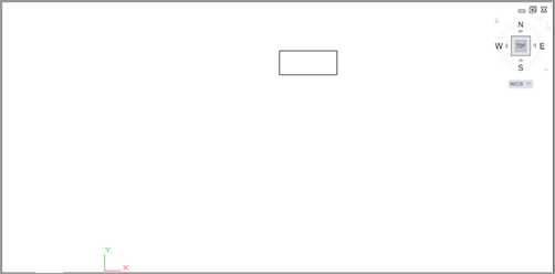
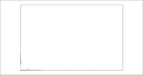
4. Click Zoom All from the Zoom flyout in the navigation bar, or type Z↵A↵. Although it appears that nothing has changed, your drawing area is now set to a size that will enable you to draw your bathroom at full scale.
5. Move the cursor to the upper-right corner of the drawing area and watch the coordinate readout. Notice that now the upper-right corner has a Y coordinate of approximately 8´-6˝, or 210 for metric users. The X coordinate depends on the proportion of your AutoCAD window. The coordinate readout also displays distances in feet and inches.
6. Click the Grid Display tool in the status bar to turn off the grid.
In step 5, the coordinate readout shows you that your drawing area is larger than before. The background grid can help you visualize the area you’re working with. You can control the grid using the Grid Display tool in the status bar, which you’ll learn about toward the end of this chapter. Grid Display shows a background grid that helps you visualize distances and can also show you the limits of your drawing. It can also be a bit distracting for a new user, so I’ve asked you to turn it off for now.
Looking at an Alternative to Limits
As an alternative to setting up the drawing limits, you can draw a rectangle that outlines the same area used to define the drawing limits. For example, in the previous exercise, you could use the Rectangle tool to draw a rectangle that has its lower-left corner at coordinate 0,0 and its upper-right corner at 132,102 (297,210 for metric users). You can set up the rectangle to be visible without printing using the Layer feature. You’ll learn more about layers in Chapter 5.
Coordinating with Paper Sizes
At this point, you may have questions about how your full-scale drawing will fit onto standard paper sizes. AutoCAD offers several features that give you precise control over the scale of your drawing. These features offer industry-standard scales to match your drawing with any paper size you need. You’ll learn more about these features as you work through the chapters of this book. However, if you’re anxious to find out about them, look at the sections on layouts in Chapters 8 and 16 and also check out the Annotation Scale feature in Chapter 10.
Understanding Scale Factors
When you draft manually, you work on the final drawing directly with pen and ink or pencil. With a CAD program, you’re a few steps removed from the finished product. Because of this, you need a deeper understanding of your drawing scale and how it’s derived. In particular, you need to understand scale factors. For example, one of the more common uses of scale factors is translating the size of a graphic symbol, such as a section symbol in an architectural drawing, to the final plotted text size. When you draw manually, you draw your symbol at the size you want. In a CAD drawing, you need to translate the desired final symbol size to the drawing scale.
When you start adding graphic symbols to your drawing (see Chapter 4), you have to specify a symbol height. The scale factor helps you determine the appropriate symbol height for a particular drawing scale. For example, you may want your symbol to appear ½˝ high in your final plot. But if you draw your symbol to ½˝ in your drawing, it appears as a dot when plotted. The symbol has to be scaled up to a size that, when scaled back down at plot time, appears ½˝ high. For a ¼˝ scale drawing, you multiply the ½˝ text height by a scale factor of 48 to get 24˝. Your symbol should be 24˝ high in the CAD drawing in order to appear ½˝ high in the final plot. Where did the number 48 come from?
The scale factor for fractional inch scales is derived by multiplying the denominator of the scale by 12 and then dividing by the numerator. For example, the scale factor for ¼˝ = 1´-0˝ is (4 × 12) / 1, or 48/1. For 3/16˝ = 1´-0˝ scale, the operation is (16 × 12) / 3, or 64. For whole-foot scales such as 1˝ = 10´, multiply the feet side of the equation by 12. Metric scales require simple decimal conversions.
You can also use scale factors to determine your drawing limits. For example, if you have a sheet size of 11˝ × 17˝ and you want to know the equivalent full-scale size for a ¼˝ scale drawing, you multiply the sheet measurements by 48. In this way, 11˝ becomes 528˝ (48 × 11˝), and 17˝ becomes 816˝ (48 × 17˝). Your work area must be 528˝ × 816˝ if you intend to have a final output of 11˝ × 17˝ at ¼˝ = 1´. You can divide these inch measurements by 12˝ to get 44´ × 68´.
Table 3-2 shows scale factors as they relate to standard drawing scales. These scale factors are the values by which you multiply the desired final printout size to get the equivalent full-scale size. If you’re using the metric system, you can use the drawing scale directly as the scale factor. For example, a drawing scale of 1:10 has a scale factor of 10, a drawing scale of 1:50 has a scale factor of 50, and so on. Metric users need to take special care regarding the base unit. Centimeters are used as a base unit in the examples in this book, which means that if you enter a distance as 1, you can assume the distance to be 1 cm.
Table 3-2: Scale conversion factors

In older drawings, scale factors were used to determine text height and dimension settings. Chances are you will eventually have to work with drawings created by older AutoCAD versions, so understanding scale factors will pay off later. Plotting to a particular scale is also easier with an understanding of scale factors.
Using Polar Tracking
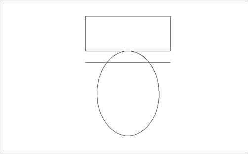
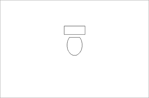
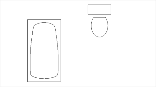
In this section, you’ll draw the first item in the bathroom: the toilet. It’s composed of a rectangle representing the tank and a truncated ellipse representing the seat. To construct the toilet, you’ll use Polar Tracking, which is one of the more versatile drafting tools. Polar Tracking helps you align your cursor to exact horizontal and vertical angles, much like a T-square and triangle.
In this exercise, you’ll use Polar Tracking to draw a rectangular box:
1. Start a line at the coordinate 5´-7˝, 6´-3˝ by entering L↵ 5´7˝,6´3˝↵. Metric users should enter L↵ 171,189↵ as the starting coordinate. This starting point is somewhat arbitrary, but by entering a specific starting location, you’re coordinated with the figures and instructions in this book. You can also use the Line tool in the Draw panel to start the line.
2. Make sure Polar Tracking is on (the Polar Tracking tool in the status bar should be blue), and then point the cursor directly to the right of the last point. The Polar Tracking cursor appears along with the Polar Tracking readout.
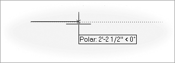
3. With the cursor pointing directly to the right, enter 1´-10˝↵. Metric users should enter 56↵. You can use the spacebar in place of the ↵ key when entering distances in this way.
4. Point the cursor downward, enter 9↵ for 9˝, and click this point. Metric users should enter 23↵.
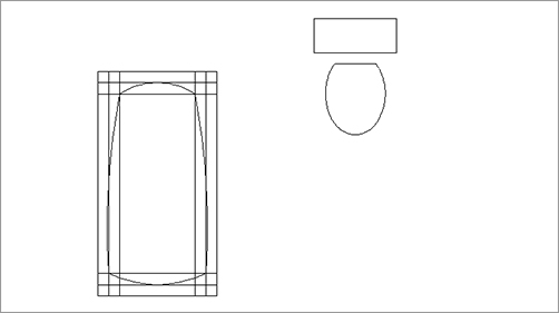
5. Continue drawing the other two sides of the rectangle by using Polar Tracking. After you’ve completed the rectangle, press ↵ or the Esc key to exit the Line tool. You should have a drawing that looks like Figure 3-2.
Figure 3-2: A plan view of the toilet tank
As you can see from the exercise, you can use Polar Tracking to restrain your cursor to horizontal and vertical positions, just as you would use a T-square and triangle. Later, you’ll learn how you can set up Polar Tracking to set the angle to any value you want in a way similar to an adjustable triangle.
In some situations, you may find that you don’t want Polar Tracking on. You can turn it off by clicking the Polar Tracking tool in the status bar. You can also press the F10 function key to turn Polar Tracking on or off.
Although this exercise tells you to use the Line tool to draw the tank, you can also use the Rectangle tool. The Rectangle tool creates what is known as a polyline, which is a set of line or arc segments that act like a single object. You’ll learn more about polylines in Chapter 19.
By using the Snap modes in conjunction with the coordinate readout and Polar Tracking, you can locate coordinates and measure distances as you draw lines. This is similar to the way you draw when using a scale. The smallest distance registered by the coordinate readout and Polar Tracking readout depends on the area you’ve displayed on your screen. For example, if you’re displaying an area the size of a football field, the smallest distance you can indicate with your cursor may be 6˝, or 15 cm. On the other hand, if your view is enlarged to show an area of only one square inch or centimeter, you can indicate distances as small as 1/1000 of an inch or centimeter by using your cursor.
Setting the Polar Tracking Angle
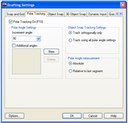
You’ve seen how Polar Tracking lets you draw exact vertical and horizontal lines. You can also set Polar Tracking to draw lines at other angles, such as 30° or 45°. To change the angle Polar Tracking uses, you use the Polar Tracking tab in the Drafting Settings dialog box (see Figure 3-3).
Right-click the Polar Tracking tool in the status bar, and then choose Settings from the shortcut menu to open the Drafting Settings dialog box. As an alternative, you can type DS↵ and then click the Polar Tracking tab.
To change the Polar Tracking angle, enter an angle in the Increment Angle text box or select a predefined angle from the drop-down list. You can do this while drawing a series of line segments, for example, so that you can set angles on the fly.
Figure 3-3: The Polar Tracking tab in the Drafting Settings dialog box
Ortho Mode
Besides using Polar Tracking mode, you can restrain the cursor to a vertical or horizontal direction by using Ortho mode. To use Ortho mode, hold down the Shift key while drawing. You can also press F8 or click Ortho Mode in the status bar to keep Ortho mode on while you draw. When you move the cursor around while drawing objects, the rubber-banding line moves only vertically or horizontally. With Ortho mode turned on, Polar Tracking is automatically turned off.
Numerous other settings are available in the Polar Tracking tab. Here is a listing of their functions for your reference:
Additional Angles This setting lets you enter a specific angle for Polar Tracking. For example, if you want Polar Tracking to snap to 12 degrees, click the New button next to the Additional Angles list box and enter 12. The value you enter appears in the list box, and when the Additional Angles check box is selected, Polar Tracking snaps to 12°. To delete a value from the list box, highlight it and click the Delete button.
The Additional Angles option differs from the Increment Angle setting in that the latter causes Polar Tracking to snap to every increment of its setting, whereas Additional Angles snaps only to the angle specified. You can enter as many angles as you want in the Additional Angles list box. As a shortcut, you can use the Polarang system variable (Polarang↵) to set the incremental angle without using the dialog box.
Object Snap Tracking Settings These settings let you control whether Object Snap Tracking uses strictly orthogonal directions (0°, 90°, 180°, and 270°) or the angles set in the Polar Angle Settings group in this dialog box. (See the section “Aligning Objects by Using Object Snap Tracking” later in this chapter.)
Polar Angle Measurement These radio buttons let you determine the zero angle on which Polar Tracking bases its incremental angles. The Absolute option uses the current AutoCAD setting for the 0° angle. The Relative To Last Segment option uses the last drawn object as the 0° angle. For example, if you draw a line at a 10° angle and the Relative To Last Segment option is selected with Increment Angle set to 90°, Polar Tracking snaps to 10°, 100°, 190°, and 280°, relative to the actual 0° direction.
The following sections present some of the more common AutoCAD commands and show you how to use them to complete a simple drawing. As you draw, watch the prompts and notice how your responses affect them. Also notice how you use existing drawing elements as reference points.
While drawing with AutoCAD, you create simple geometric forms to determine the basic shapes of objects, and you can then modify the shapes to fill in detail.
AutoCAD offers a number of basic 2D drawing object types; lines, arcs, circles, text, dimensions, traces, polylines, points, ellipses, elliptical arcs, spline curves, regions, hatches, and multiline text are the most common. All drawings are built on at least some of these objects. In addition, there are several 3D solids and meshes, which are three-dimensional shapes. You’re familiar with lines and arcs; these, along with circles, are the most commonly used objects. As you progress through the book, you’ll learn about the other objects and how they’re used. You’ll also learn about 3D objects in the section on AutoCAD 3D.
Locating an Object in Reference to Others
To define the toilet seat, you’ll use an ellipse. Follow these steps:
1. Click the Center Ellipse tool in the Home tab’s Draw panel, or type El↵.
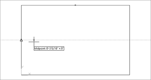
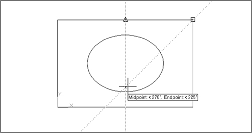
2. At the Specify axis endpoint of ellipse or [Arc/Center]: prompt, pick the midpoint of the bottom horizontal line of the rectangle. To do this, Shift+right-click to open the Object Snap shortcut menu and select Midpoint; then move the cursor toward the bottom line. (Remember, Shift+click the right mouse button to open the Object Snap menu.) When you see the Midpoint Osnap marker on the line, click the left mouse button.

3. At the Specify other endpoint of axis: prompt, point the cursor downward and enter 1´-10˝↵. Metric users should enter 55↵.
4. At the Specify distance to other axis or [Rotation]: prompt, point the cursor horizontally from the center of the ellipse and enter 8˝↵. Metric users should enter 20↵. Your drawing should look like Figure 3-4.
Figure 3-4: The ellipse added to the tank
Getting a Closer Look
During the drawing process, you’ll often want to enlarge areas of a drawing to edit its objects. In Chapter 1, you saw how to use the Zoom capability for this purpose. Follow these steps to enlarge the view of the toilet:
1. Click Zoom Window from the Zoom flyout in the navigation bar, or type Z↵ W↵.
2. At the Specify first corner: prompt, pick a point below and to the left of your drawing, at or near coordinate 5´-0˝,3´-6˝. Metric users should use the coordinate 150.0000,102.0000.
3. At the Specify opposite corner: prompt, pick a point above and to the right of the drawing, at or near coordinate 8´-3˝,6´-8˝ (246.0000,195.0000 for metric users). The toilet should be completely enclosed by the zoom window. You can also use the Zoom Realtime tool in conjunction with the Pan Realtime tool. The toilet enlarges to fill more of the screen. Your view should look similar to Figure 3-5 in the following section.
If you have a mouse with a scroll wheel, you can avoid using the Zoom command altogether. Just place the cursor on the toilet and turn the wheel to zoom into the image.
Modifying an Object
Now let’s see how editing commands are used to construct an object. To define the back edge of the seat, let’s put a copy of the line defining the front of the toilet tank 3˝ (7 cm for metric users) toward the center of the ellipse:
1. Click the Copy tool in the Home tab’s Modify panel, or type co↵.
2. At the Select objects: prompt, pick the horizontal line that touches the top of the ellipse. The line is highlighted. Press ↵ to complete your selection.
3. At the Specify base point or [Displacement/mOde] <Displacement>: prompt, pick a base point near the line. Then point the cursor down and enter 3˝↵, or 7↵ if you’re a metric user.
4. Press ↵ to exit the Copy command. Your drawing should look like Figure 3-5.
Figure 3-5: The line copied down
Notice that the Copy command acts exactly like the Move command you used in Chapter 2 except that Copy doesn’t alter the position of the objects you select and you must press ↵ to exit Copy.
Trimming an Object
Now you must delete the part of the ellipse that isn’t needed. You’ll use the Trim command to trim off part of the ellipse:
1. Click the Trim tool in the Home tab’s Modify panel. If you don’t see the Trim tool, click the Trim/Extend flyout and select Trim. You’ll see this prompt:
Current settings: Projection=UCS Edge=None
Select cutting edges ...
Select objects or <select all>:
2. Click the line you just created—the one that crosses through the ellipse—and press ↵ to finish your selection.
3. At the Select object to trim or shift-select to extend or [Fence/Crossing/Project/Edge/eRase/Undo]: prompt, pick the topmost portion of the ellipse above the line. This trims the ellipse back to the line.
4. Press ↵ to exit the Trim command.
In step 1 of the preceding exercise, the Trim command produces two messages in the prompt. The first message, Select cutting edges..., tells you that you must first select objects to define the edge to which you want to trim an object. In step 3, you’re again prompted to select objects, this time to select the object to trim. Trim is one of a handful of AutoCAD commands that asks you to select two sets of objects: The first set defines a boundary, and the second is the set of objects you want to edit. The two sets of objects aren’t mutually exclusive. You can, for example, select the cutting-edge objects as objects to trim. The next exercise shows how this works.
First, you’ll undo the trim you just did. Then, you’ll use the Trim command again in a slightly different way to finish the toilet:
1. Click the Undo button in the Quick Access toolbar, or enter U↵ at the Command prompt. The top of the ellipse reappears.
2. Start the Trim tool again by clicking it in the Modify panel.
3. At the Select objects or <select all>: prompt, click the ellipse and the line crossing the ellipse. (See the first image in Figure 3-6.)
4. Press ↵ to finish your selection.
5. At the Select object to trim or [Fence/Crossing/Project/Edge/eRase/Undo]: prompt, click the top portion of the ellipse, as you did in the previous exercise. The ellipse trims back.
6. Click a point near the left end of the trim line, outside the ellipse. The line trims back to the ellipse.
7. Click the other end of the line. The right side of the line trims back to meet the ellipse. Your drawing should look like the second image in Figure 3-6.
8. Press ↵ to exit the Trim command.
9. Click Save on the Quick Access toolbar to save the file in its current state, but don’t exit the file. You may want to get in the habit of doing this every 20 minutes.
Here you saw how the ellipse and the line are both used as trim objects as well as the objects to be trimmed. The Trim options you’ve seen so far—Fence, Crossing, Project, Edge, eRase, and Undo—are described in the next section in this chapter. Also note that by holding down the Shift key in step 4, you can change from trimming an object to extending an object.
Exploring the Trim Options
AutoCAD offers six options for the Trim command: Fence, Crossing, Project, Edge, eRase, and Undo. As described in the following list, these options give you a higher degree of control over how objects are trimmed:
Fence/Crossing [F or C] Lets you use a fence or crossing window to select objects.
Project [P] Useful when you’re working on 3D drawings. It controls how AutoCAD trims objects that aren’t coplanar. Project offers three options: None, UCS, and View. The None option causes Trim to ignore objects that are on different planes so that only coplanar objects are trimmed. If you choose UCS, the Trim command trims objects based on a plan view of the current UCS and then disregards whether the objects are coplanar. (See the middle of Figure 3-7.) View is similar to UCS but uses the current view’s “line of sight” to determine how non-coplanar objects are trimmed. (See the bottom of Figure 3-7.)
Figure 3-6: Trimming the ellipse and the line
Edge [E] Lets you trim an object to an apparent intersection, even if the cutting-edge object doesn’t intersect the object to be trimmed (see the top of Figure 3-7). Edge offers two options: Extend and No Extend. You can also set these options by using the Edgemode system variable.
eRase [R] Allows you to erase an object while remaining in the Trim command.
Undo [U] Causes the last trimmed object to revert to its original length.
You’ve just seen one way to construct the toilet. However, you can construct objects in many ways. For example, you can trim only the top of the ellipse, as you did in the first trim exercise, and then use the Grips feature to move the endpoints of the line to meet the endpoints of the ellipse. As you become familiar with AutoCAD, you’ll start to develop your own ways of working, using the tools best suited to your style.
If you’d like to take a break, now is a good time. You can exit AutoCAD and then come back to the Bath drawing file when you’re ready to proceed.
Figure 3-7: The Trim command’s options
Planning and Laying Out a Drawing
For the next object, the bathtub, you’ll use some new commands to lay out parts of the drawing. This will help you get a feel for the kind of planning you must do to use AutoCAD effectively. You’ll begin the bathtub by using the Line command to draw a rectangle 2´-8˝ × 5´-0˝ (81 cm × 152 cm for metric users) on the left side of the drawing area. For a change this time, you’ll use a couple of shortcut methods built into AutoCAD: the Line command’s keyboard shortcut and the Direct Distance method for specifying distance and direction.
First though, you’ll go back to the previous view of your drawing and arrange some more room to work. Follow these steps:
1. Return to your previous view, shown in Figure 3-8. A quick way to do this is to type Z↵ P↵. Your view returns to the one you had before the last Zoom command.
Figure 3-8: The view of the finished toilet after using the Zoom Previous tool. You can also obtain this view by using the Zoom All tool from the Zoom flyout.
2. Type L↵, and then enter 9,10↵ to start the line at the 0´-9˝,0´-10˝ coordinate. Metric users should enter 24,27↵ for the coordinate 24.0000,27.0000.
3. Place your cursor to the right of the last point selected, so that the rubber-banding line is pointing directly to the right, and type 2´8˝. Then press ↵ for the first side of the tub. Metric users should enter 81↵.
4. Point the rubber-banding line upward toward the top of the screen and type 5´. Then press ↵ for the next side. Metric users should enter 152↵.
5. Point the rubber-banding line directly to the left of the last point and type 2´8˝ (81 for metric users). Then press ↵ for the next side.
6. Type C↵ to close the rectangle and exit the Line command.
Instead of pressing ↵ during the Direct Distance method, you can press the spacebar, or you can right-click and choose Enter from the shortcut menu.
Now you have the outline of the tub. Notice that you don’t have to enter the at sign (@) or angle specification. Instead, you use the Direct Distance method to specify direction and distance. You can use this method for drawing lines or moving and copying objects at right angles. The Direct Distance method is less effective if you want to specify exact angles other than right angles.
Be Careful with Hyphens
When you enter feet and inches in the command window, you must avoid hyphens or spaces. Thus, 2 feet 8 inches is typed as 2´8˝. But be aware that hyphens are allowed when using the Direct Distance method.
The keyboard shortcuts for some of the tools or commands you’ve used in this chapter are CO (Copy), E (Erase), EL (Ellipse), F (Fillet), M (Move), O (Offset), and TR (Trim). Remember that you can enter keyboard shortcuts, such as keyboard commands, only when the Command prompt is visible in the Command window.
Making a Preliminary Sketch
In this section, you’ll see how planning ahead will make your use of AutoCAD more efficient. When drawing a complex object, you’ll often have to do some layout before you do the actual drawing. This is similar to drawing an accurate pencil sketch using construction lines that you later trace over to produce a finished drawing. The advantage of doing this in AutoCAD is that your drawing doesn’t lose any accuracy between the sketch and the final product. Also, AutoCAD enables you to use the geometry of your sketch to aid in drawing. While you’re planning your drawing, think about what you want to draw, and then decide which drawing elements will help you create that object.
You’ll use the Offset command to establish reference lines to help you draw the inside of the tub. This is where the Osnap overrides are useful. (See the sidebar “The Osnap Options” later in this chapter.)
You can use the Offset tool on the Home tab’s Modify panel to make parallel copies of a set of objects, such as the lines forming the outside of your tub. Offset is different from the Copy command; while Offset allows only one object to be copied at a time, it can remember the distance you specify. The Offset option doesn’t work with all types of objects. Only lines, arcs, circles, ellipses, splines, and 2D polylines can be offset.
Standard lines are best suited for the layout of the bathtub in this situation. In Chapter 6, you’ll learn about two other objects, construction lines and rays, which are specifically designed to help you lay out a drawing. In this exercise, you’ll use standard lines:
1. Click the Offset tool in the Home tab’s Modify panel, or type O↵.
2. At the Specify offset distance or [Through/Erase/Layer] <Through>: prompt, enter 3↵. This specifies the distance of 3˝ as the offset distance. Metric users should enter 7 for 7 cm, which is roughly equivalent to 3 inches.
3. At the Select object to offset or [Exit/Undo] <Exit>: prompt, click the bottom line of the rectangle you just drew.
4. At the Specify point on side to offset or [Exit/Multiple/Undo]: prompt, pick a point inside the rectangle. A copy of the line appears. You don’t have to be exact about where you pick the side to offset; AutoCAD only wants to know on which side of the line you want to make the offset copy.
5. The prompt Select object to offset or [Exit/Undo] <Exit>: appears again. Click another side to offset. Then click again on a point inside the rectangle.
6. Continue to offset the other two sides. Then offset these four new lines inside the rectangle toward the center. You’ll have a drawing that looks like Figure 3-9.
7. When you’re done, exit the Offset command by pressing ↵.
Using the Layout
Now you’ll begin to draw the inside of the tub, starting with the narrow end. You’ll use your offset lines as references to construct the arcs that make up the tub. Also in this exercise, you’ll set up some of the osnap options to be available automatically whenever AutoCAD expects a point selection. Here are the steps:
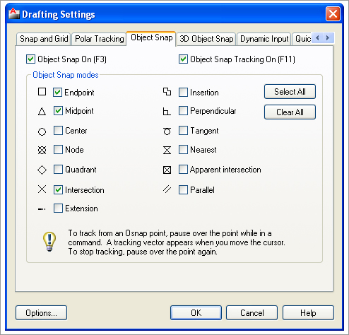
1. Right-click the Object Snap tool in the status bar and select Settings from the shortcut menu. You can also type Os↵.
2. Click the Clear All button to turn off any options that may be selected.
Figure 3-9: The completed layout
Look at the graphic symbols next to each of the osnap options in the Object Snap tab. These are the Osnap markers that appear in your drawing as you select osnap points. Each osnap option has its own marker symbol. As you use the osnaps, you’ll become more familiar with how they work.
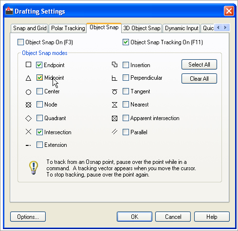
3. Click the Endpoint, Midpoint, and Intersection check boxes so that a checkmark appears in each box, and make sure the Object Snap On option is selected. Click OK (see Figure 3-10).
Figure 3-10: The Object Snap tab in the Drafting Settings dialog box
You’ve just set up the Endpoint, Midpoint, and Intersection osnaps to be on by default. This is called a Running Osnap; AutoCAD automatically selects the nearest osnap point without your intervention. Now let’s see how a Running Osnap works:
1. First, turn off Dynamic Input mode in the status bar. This will help you see the osnap markers more easily.
2. Click the 3-Point Arc tool in the Home tab’s Draw panel or type a↵. See Figure 3-11 for other Arc options available from the Draw panel’s Arc flyout.
Figure 3-11: The Arc flyout on the Draw panel offers several ways to draw an arc.
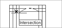
3. For the first point of the arc, move the cursor toward the intersection of the two lines as indicated in the top image in Figure 3-12. Notice that the Intersection Osnap marker appears on the intersection.
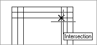
4. With the Intersection Osnap marker on the desired intersection, click the left mouse button.
Figure 3-12: Drawing the top, left side, and bottom of the tub
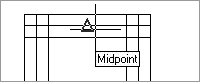
5. Move the cursor to the midpoint of the second horizontal line near the top. When the Midpoint Osnap marker appears at the midpoint of the line, click the left mouse button.
6. Use the Intersection Osnap marker to locate and select the intersection of the two lines at the upper-left side of the bathtub.
The top image in Figure 3-12 shows the sequence I just described.
If you have several Running Osnap modes on (Endpoint, Midpoint, and Intersection, for example), pressing the Tab key cycles through those osnap points on the object. This feature can be especially useful in a crowded area of a drawing.
Adjusting the AutoSnap Feature
When you click the Options button in the Object Snap tab of the Drafting dialog box, you’ll see the Drafting Settings tab of the Options dialog box. This tab offers a set of options pertaining to the AutoSnap feature. AutoSnap looks at the location of your cursor during osnap selections and locates the osnap point nearest your cursor. AutoSnap then displays a graphic called a marker showing you the osnap point it has found. If it’s the one you want, left-click your mouse to select it.
The AutoSnap settings enable you to control various features:
Marker Turns the graphic marker on or off.
Magnet Causes the Osnap cursor to jump to inferred osnap points.
Display AutoSnap Tooltip Turns the Osnap tool tip on or off.
Display AutoSnap Aperture Box Turns the old-style Osnap cursor box on or off.
Colors Controls the color of the AutoSnap marker. This option opens the Drawing Window Colors dialog box, which lets you select a color.
AutoSnap Marker Size Controls the size of the graphic marker.
Next, you’ll draw an arc for the left side of the tub:
1. Click the Arc tool in the Draw panel again.
2. Type @↵ to select the last point you picked as the start of the next arc.
It’s easy for new users to select points inadvertently. If you accidentally select additional points after the last exercise and prior to step 1, you may not get the results described here. If this happens, issue the Arc command again; then, use the Endpoint osnap and select the endpoint of the last arc.
3. Type E↵ to tell AutoCAD that you want to specify the other end of the arc instead of the next point. As another option, you can right-click anywhere in the drawing area and choose End from the shortcut menu.
4. At the Specify end point of arc: prompt, use the Intersection osnap to pick the intersection of the two lines in the lower-left corner of the tub. See the middle image in Figure 3-12 for the location of this point.
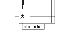
5. Type D↵ to select the Direction option. You can also right-click anywhere in the drawing area and then choose Direction from the shortcut menu. The arc drags as you move the cursor, along with a rubber-banding line from the starting point of the arc.
6. Move the cursor to the left of the dragging arc until it touches the middle line on the left side of the tub. Pick that line, as shown in the middle image in Figure 3-12. You may need to turn off osnaps temporarily to do this.
In step 5 of the preceding exercise, the rubber-banding line indicates the direction of the arc. Be sure Ortho mode is off because Ortho mode forces the rubber-banding line and the arc in a direction you don’t want. Check the status bar; if the Ortho tool is blue (on), press F8 or click the Ortho tool to turn off Ortho mode.
Now, you’ll draw the bottom of the tub:
1. Click the Arc tool in the Draw panel again. You can also press ↵ to replay the last command.
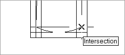
2. Using the Endpoint Osnap marker, pick the endpoint of the bottom of the arc just drawn.
3. Using the Midpoint Osnap marker, pick the middle horizontal line at the bottom of the tub.
4. Pick the intersection of the two lines in the lower-right corner of the tub. (See the image at the bottom in Figure 3-12.)
Next, create the right side of the tub by mirroring the left side:
1. Click the Mirror tool on the Home tab’s Modify panel. You can also enter mi↵ at the Command prompt.
2. At the Select objects: prompt, pick the long arc on the left side of the tub to highlight the arc. Press ↵ to indicate that you’ve finished your selection.
3. At the Specify first point of mirror line: prompt, pick the midpoint of the top horizontal line. By now, you should know how to use the automatic osnap modes you set up earlier.
4. At the Specify second point of mirror line: prompt, use Polar Tracking mode to pick a point directly below the last point selected.
5. At the Erase source objects? [Yes/No] <N>: prompt, press ↵ to accept the Mirror command’s default Erase source objects option (No) and exit the Mirror command. A mirror image of the arc you picked appears on the right side of the tub. Your drawing should look like Figure 3-13.
Figure 3-13: The inside of the tub completed with the layout lines still in place
In this exercise, you were able to use osnaps in a Running Osnap mode. You’ll find that you’ll use osnaps constantly as you create your drawings. For this reason, you may want Running Osnaps on all the time. Even so, at times Running Osnaps can get in the way. For example, they may be a nuisance in a crowded drawing when you want to use a zoom window. The osnaps can cause you to select an inappropriate window area by automatically selecting osnap points.
Fortunately, you can toggle Running Osnaps on and off easily by clicking the Object Snap tool in the status bar. If you don’t have any Running Osnaps set, clicking the Object Snap tool opens the Object Snap settings in the Drafting Settings dialog box, enabling you to select your osnaps. Or you can right-click the Object Snap tool and select Settings from the shortcut menu that appears.
Erasing the Layout Lines
Next, you’ll erase the layout lines you created using the Offset command. But this time, you’ll try selecting the lines before issuing the Erase command.
Follow these steps:
1. Click each internal layout line individually.
If you have problems selecting just the lines, try using a selection window to select single lines. (Remember, a window selects only objects that are completely within it.)
2. After all the layout lines are highlighted, enter E↵ to use the keyboard shortcut for the Erase command, or right-click and choose Erase from the shortcut menu. Your drawing will look like Figure 3-14.
Figure 3-14: The drawing after erasing the layout lines

If you right-clicked to use the shortcut menu in step 2, you’ll notice that you have several options besides Erase. You can move, copy, scale, and rotate the objects you selected. These options are similar to the tools on the Home tab’s Modify panel in the way they act. But be aware that they act somewhat differently from the hot-grip options described in Chapter 2.
The Osnap Options
Earlier, you made several of the osnap settings automatic so they’re available without having to select them from the Osnap shortcut menu. Another way to invoke the osnap options is to type their keyboard equivalents while selecting points or to Shift+right-click and type the capital letter shown in the Osnap shortcut menu for the option you want to use.
The following is a summary (in alphabetic order) of all the available osnap options, including their keyboard shortcuts. You’ve already used many of these options in this chapter and in the previous chapter. Pay special attention to those options you haven’t yet used in the exercises but may find useful to your style of work. The full name of each option is followed by its keyboard shortcut name in brackets. To use these options, you can enter either the full name or the abbreviation at any point prompt. You can also select these options from the pop-up menu obtained by Shift+clicking the right mouse button.
Apparent Intersection [app] Selects the apparent intersection of two objects. This is useful when you want to select the intersection of two objects that don’t actually intersect. You’ll be prompted to select the two objects.
Center [cen] Selects the center of an arc or a circle. You must click the arc or circle itself, not its apparent center.
Endpoint [endp or end] Selects the endpoints of lines, polylines, arcs, curves, and 3D Face vertices.
Extension [ext] Selects a point that is aligned with an imagined extension of a line. For example, you can pick a point in space that is aligned with an existing line but isn’t on that line. To use that point, type ext↵ during point selection or select Extension from the Osnap pop-up menu. Then move the cursor to the line whose extension you want to use and hold it there until you see a small, cross-shaped marker on the line. The cursor also displays a tool tip with the word extension, letting you know that the Extension osnap is active.
From [fro] Selects a point relative to a picked point. For example, you can select a point that is 2 units to the left and 4 units above a circle’s center. This option is usually used in conjunction with another osnap option, such as From Endpoint or From Midpoint.
Insert [ins] Selects the insertion point of text, blocks, Xrefs, and overlays.
Intersection [int] Selects the intersection of objects.
Mid Between 2 Points [m2p] Selects a point that is midway between two other points.
Midpoint [mid] Selects the midpoint of a line or an arc. In the case of a polyline, it selects the midpoint of the polyline segment.
Nearest [nea] Selects a point on an object nearest the pick point.
Node [nod] Selects a point object.
None [non] Temporarily turns off Running Osnaps for a single point selection.
Parallel [par] Lets you draw a line segment that is parallel to another existing line segment. To use this option, type par↵ during point selection, or select Parallel from the Osnap pop-up menu. Then move the cursor to the line you want to be parallel to and hold it there until you see a small, cross-shaped marker on the line. The cursor also displays a tool tip with the word parallel, letting you know that the Parallel osnap is active.
Perpendicular [per] Selects a position on an object that is perpendicular to the last point selected.
Point filters Not really object snaps, but point-selection options that let you filter X, Y, or Z coordinate values from a selected point. (See Chapter 21 for more on point filters.)
Quadrant [qua] Selects the nearest cardinal (north, south, east, or west) point on an arc or a circle.
Tangent [tan] Selects a point on an arc or a circle that represents the tangent from the last point selected.
Temporary Track Point Provides an alternate method for using the Object Snap Tracking feature described later in this chapter. (See Chapter 15 for more on Temporary Track Point.)
3D Osnaps Offers additional osnaps for 3D modeling. With these osnap options, you can select a vector that is perpendicular to a surface or find the midpoint of an edge of a 3D object.
Sometimes you’ll want one or more of these osnap options available as the default selection. Remember that you can set Running Osnaps to be on at all times. Type DS↵, and then click the Object Snap tab. You can also right-click the Object Snap tool in the status bar and choose Settings from the shortcut menu to open the Drafting Settings dialog box, or just select osnap options directly from the shortcut menu.
If you need more control over the selection of objects, you’ll find the Add/Remove Selection Mode setting useful. This setting lets you deselect a set of objects within a set of objects you’ve already selected. While in Object Selection mode, enter R↵, then proceed to use a window or other selection tool to remove objects from the selection set. Enter A↵ to continue to add options to the selection set. Or, if you need to deselect only a single object, Shift+click it.
Putting On the Finishing Touches
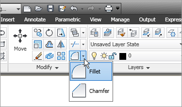
The inside of the tub still has some sharp corners. To round out these corners, you can use the versatile Fillet tool on the Home tab’s Modify panel. Fillet enables you to join lines and arcs end to end, and it can add a radius where they join so there is a smooth transition from arc to arc or line to line. Fillet can join two lines that don’t intersect, and it can trim two crossing lines back to their point of intersection.
Another tool, called Chamfer, performs a similar function, but instead of joining lines with an arc, Chamfer joins lines with another line segment. Since they perform similar functions, Fillet and Chamfer occupy the same location on the Modify panel. If you don’t see the Fillet tool, click the Chamfer flyout and select Fillet.
Continue with your tutorial by following these steps:
1. Click the Fillet tool on the Home tab’s Modify panel, or type f↵.
2. At the prompt
Current settings: Mode = TRIM, Radius = 0´-0 1/2˝
Select first object or [Undo/Polyline/Radius/Trim/Multiple]:
enter R↵, or right-click and choose Radius from the shortcut menu.
3. At the Specify fillet radius <0´-0˝>: prompt, enter 4↵. This tells AutoCAD that you want a 4˝ radius for your fillet. Metric users should enter 10↵.
4. Pick two adjacent arcs. The fillet arc joins the two larger arcs.
5. Press ↵ again, and fillet another corner. Repeat until all four corners are filleted. Your drawing should look like Figure 3-15.
Aligning Objects by Using Object Snap Tracking
You saw how to use lines to construct an object such as the bathtub. In many situations, using these construction lines is the most efficient way to draw, but they can also be a bit cumbersome. AutoCAD offers another tool that helps you align locations in your drawing to existing objects without having to draw intermediate construction lines. The tool is called Object Snap Tracking, or Osnap Tracking.
Figure 3-15: A view of the finished toilet and tub with the tub corners filleted
Osnap Tracking is like an extension of object snaps that enables you to align a point to the geometry of an object instead of just selecting a point on an object. For example, with Osnap Tracking, you can select a point that is exactly at the center of a rectangle.
In the following exercises, you’ll draw a plan view of a bathroom sink as an introduction to the Osnap Tracking feature. This drawing will be used as a symbol in later chapters.
Getting Set Up
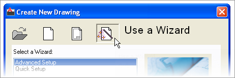
First, as a review, you’ll open a new file by using the Create New Drawing Wizard. Because this drawing will be used as a symbol for insertion in other CAD drawings, don’t worry about setting it up to conform to a sheet size. Chances are you won’t be printing individual symbols. Here are the steps:
1. Enter Startup↵ 1↵. This turns on the Create New Drawing Wizard for new drawings.
2. Click the New tool from the Quick Access toolbar to create a new drawing for your bathroom sink.
3. Click the Use A Wizard button in the Create New Drawing dialog box.
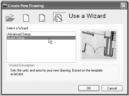
4. Select Quick Setup from the list that appears below the buttons, and then click OK (see Figure 3-16).
5. In the Units screen, choose Architectural and then click Next. Metric users can use the Decimal option. This option performs the same operation as the Drawing Units dialog box you saw earlier in this chapter.
Figure 3-16: The Create New Drawing dialog box
6. In the Area screen, enter 48 for the width and 36 for the length. Metric users should enter 122 for the width and 92 for the length. Click Finish. This option performs the same operation as the Limits command you used earlier.
7. Type Z↵ A↵ to display the overall area of the drawing set by the limits.
8. Choose Save As from the Application menu to save the file under the name Sink.
9. Enter Startup↵ 0↵ to turn off the Create New Drawing Wizard option. You can leave it turned on if you wish, but be aware that later exercises assume that it is turned off.
As you saw in steps 5 and 6, the Create New Drawing Wizard simplifies the drawing setup process by limiting the options with which you need to work.
If you find that you use the same drawing setup over and over, you can create template files that are already set up to your own, customized way of working. Templates are discussed in Chapter 6.
Drawing the Sink
You’re ready to draw the sink. First, you’ll draw the sink countertop. Then, you’ll make sure Running Osnaps and Osnap Tracking are turned on. Finally, you’ll draw the bowl of the sink.
Here are the steps for drawing the outline of the sink countertop:
1. If the grid is on, click the Grid tool in the status bar to turn it off.
2. Click the Rectangle tool in the Draw panel, or type rec↵.
3. At the prompt
Specify first corner point or [Chamfer/Elevation/Fillet/Thickness/Width]:
enter 0,0↵. This places one corner of the rectangle in the origin of the drawing.
4. At the Specify other corner point or [Area/Dimensions/Rotation]: prompt, enter @2´4,1´6↵ to place the other corner of the rectangle. Metric users should enter @71,46↵. This makes the rectangle 2´-4˝ wide and 1´-6˝ deep, or 71 cm wide and 46 cm deep for metric users. The rectangle appears in the lower half of the drawing area.
5. Click Zoom Extents from the Zoom flyout on the navigation bar or type Z↵ E↵. This enlarges the view of the sink outline so it fits in the drawing area.
6. Use the Zoom Realtime tool in the Zoom flyout to adjust your view so it looks similar to the one shown in Figure 3-17. You can also enter Z↵↵ to start the realtime zoom feature or just use your scroll wheel.
Figure 3-17: The view of the sink countertop after making some adjustments
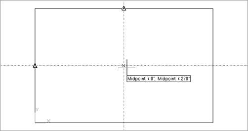
When you draw the bowl of the sink, the bowl will be represented by an ellipse. You want to place the center of the ellipse at the center of the rectangle you’ve just drawn. To do this, you’ll use the midpoint of two adjoining sides of the rectangle as alignment locations. This is where the Osnap Tracking tool will be useful.
You need to make sure the Object Snap tool is turned on and that the Midpoint Object Snap option is also turned on. Then you’ll make sure Osnap Tracking is turned on. Use these steps:
1. Right-click the Object Snap Tracking tool in the status bar and choose Settings from the shortcut menu to open the Drafting Settings dialog box at the Object Snap tab (see Figure 3-18).
2. Make sure the Midpoint check box in the Object Snap Modes group is selected.
3. Also make sure Object Snap On and Object Snap Tracking On are both selected. Click OK. You’ll notice that the Object Snap and Object Snap Tracking buttons in the status bar are now in the on position.
Figure 3-18: The Object Snap tab in the Drafting Settings dialog box
Finally, you’re ready to draw the ellipse:
1. Click the Center Ellipse tool in the Draw panel, or enter El↵.
2. Move your cursor to the top, horizontal edge of the rectangle until you see the Midpoint tool tip.
3. Move the cursor directly over the Midpoint Osnap marker. Without clicking the mouse, hold the cursor there for a second until you see a small cross appear. Look carefully, because the cross is small. This is the Object Snap Tracking marker (see Figure 3-19).
Figure 3-19: The Object Snap Tracking marker
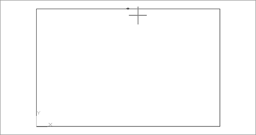
You can alternately insert and remove the Object Snap Tracking marker by passing the cursor over the Osnap marker.
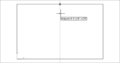
4. As you move the cursor downward, a dotted line appears, emanating from the midpoint of the horizontal line. The cursor also shows a small X following the dotted line as you move it (see Figure 3-20).
Figure 3-20: A vertical dotted line appears.
5. Move the cursor to the midpoint of the left vertical side of the rectangle. Don’t click, but hold it there for a second until you see the small cross. Now as you move the cursor away, a horizontal dotted line appears with an X following the cursor (see Figure 3-21).
Figure 3-21: A horizontal dotted line appears.
6. Move the cursor to the center of the rectangle. The two dotted lines appear simultaneously and a small X appears at their intersection (see Figure 3-22).
Figure 3-22: The vertical and horizontal dotted lines appear simultaneously.
7. With the two dotted lines crossing and the X at their intersection, click the left mouse button to select the exact center of the rectangle.
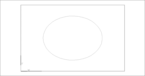
8. Point the cursor to the right, and enter 8↵ to make the width of the bowl 16˝. Metric users should enter 20↵ for a bowl 40 cm wide.
9. Point the cursor downward, and enter 6↵ to make the length of the bowl 12˝. Metric users should enter 15↵ for a bowl with a length of 30 cm. The basic symbol for the sink is complete (see Figure 3-23).
10. Click Save in the Quick Access toolbar and close the current file. You can also save and close the Bath file and exit AutoCAD.
In this exercise, you saw how Object Snap Tracking enables you to align two locations to select a point in space. Although you used only the Midpoint osnap setting in this exercise, you aren’t limited to one osnap setting. You can use as many as you need to select the appropriate geometry. You can also use as many alignment points as you need, although in this exercise you used only two. If you like, erase the ellipse and repeat this exercise until you get the hang of using the Object Snap Tracking feature.
Figure 3-23: The completed bathroom sink
As with all the other tools in the status bar, you can turn Object Snap Tracking on or off by clicking the Object Snap Tracking tool.
Using the AutoCAD Modes as Drafting Tools
Before you finish this chapter, you’ll want to know about a few of the other drafting tools that are common to drawing programs. These tools may be compared to a background grid (Grid mode) and the ability to “snap” to grid points (Snap mode). These drawing modes can be indispensable tools under certain conditions. Their use is fairly straightforward. You can experiment with them on your own using the information in the following sections.
Using Grid Mode as a Background Grid
Using Grid mode is like having a grid under your drawing to help you with layout, as shown in Figure 3-24. In this figure, the grids are set to a 1´ spacing with major grid lines at 5´. The grid also shows, in darker lines, the X and Y axis that start at the origin of the drawing.
Figure 3-24: A sample drawing showing the grids turned on
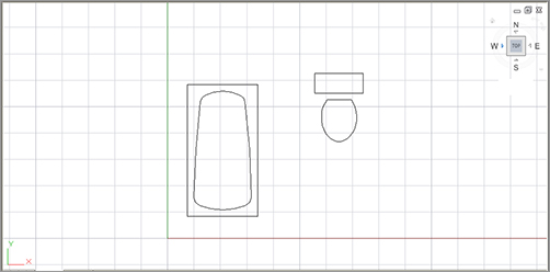
Grids will not print in your final output. They are a visual aid to help you gauge distances. In AutoCAD, Grid mode can also let you see the limits of your drawing because the grid can be set to display only within the limits setting of your drawing. Grid mode can help you visually determine the distances with which you’re working in any given view. In this section, you’ll learn how to control the grid’s appearance. The F7 key toggles Grid mode on and off. You can also click the Grid Display tool in the status bar.
Using Object Snap Tracking and Polar Tracking Together
In addition to selecting as many tracking points as you need, you can use different angles besides the basic orthogonal angles of 0°, 90°, 180°, and 270°. For example, you can have AutoCAD locate a point that is aligned vertically to the top edge of the sink and at a 45° angle from a corner.
This can be accomplished by using the settings in the Polar Tracking tab of the Drafting Settings dialog box. (See the section “Setting the Polar Tracking Angle” earlier in this chapter.) If you set the increment angle to 45° and turn on the Track Using All Polar Angle Settings option, you’ll be able to use 45° in addition to the orthogonal directions. You’ll see firsthand how this works in Chapter 6.
To set up the grid spacing, follow these steps:
1. Right-click the Grid Display tool in the status bar and select Settings (or type Ds↵) to open the Drafting Settings dialog box, showing all the mode settings.
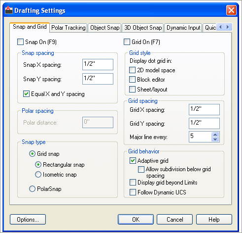
2. Click the Snap And Grid tab if it isn’t already selected. You see six groups: Snap Spacing, Grid Style, Grid Spacing, Polar Spacing, Grid Behavior, and Snap Type. Notice that the Grid X Spacing text box contains a value of 1/2˝. Metric users see a value of 10 (see Figure 3-25).
3. Enter the grid spacing you want in the Grid X Spacing and Grid Y Spacing input boxes.
4. Click the Grid On check box to make the grid visible. Notice the F7 in parentheses: This tells you that the F7 function key also controls the Grid On/Off function. Click OK to dismiss the Drafting Settings dialog box and save your settings.
Figure 3-25: The Snap And Grid tab of the Drafting Settings dialog box
If you prefer, you can use the Gridunit system variable to set the grid spacing. Enter Gridunit↵, and at the Enter new value for GRIDUNIT <0´-0 ½˝,0´-0 ½˝>: prompt, enter a grid spacing in X,Y coordinates. You must enter the Gridunit value as an X,Y coordinate.
There are several other grid options in the Drafting Settings dialog box. The Grid Style group lets you display the grid as a series of dots instead of the graph-paper-style lines. Place a check by the view name where you want to display dots instead of grid lines.
In the Grid Behavior group, the Display Grid Beyond Limits check box lets you determine whether the grid displays outside the limits of the drawing.
The Adaptive Grid option adjusts the grid spacing depending on how much of the view is displayed. If you zoom out to a point where the grid becomes too dense to view the drawing, the grid automatically increases its interval. The Major Line Every option lets you control how frequently the major grid lines (lines that appear darker than the others) appear.
Once you’ve set up your grid, you can press F7 or click Grid in the status bar to turn the grid on and off. (You can also hold down the Ctrl key and press G.)
Using the Snap Modes
The Snap mode forces the cursor to move in steps of a specific distance. Snap mode is useful when you want to select points on the screen at a fixed interval. Two snap modes are available in AutoCAD: Grid Snap and Polar Snap. The F9 key toggles Grid Snap mode on and off, or you can click the Snap tool in the status bar. Follow these steps to access the Snap mode:
1. Right-click the Grid Display tool in the status bar and select Settings (or type Ds↵) to open the Drafting Settings dialog box.
2. In the Snap Spacing group of the dialog box, double-click the Snap X Spacing text box and enter a value for your snap spacing. Then press the Tab key to move to the next option. AutoCAD assumes you want the X and Y snap spacing to be the same unless you specifically ask for a different Y setting.
3. You can click the Snap On check box to turn on Snap mode from this dialog box.
4. Click OK to save your settings and close the dialog box.
Controlling the Color of Grid Lines
If you find that the colors of the grid lines are too strong and they obscure your drawing, you can set them so they blend into the background. To do this, you use the Options dialog box (see Appendix B for more on the Options dialog box):
1. Right-click and select Options or type Options↵.
2. Select the Display tab.
3. Click the Colors button in the Window Elements group.
4. Make sure 2D Model Space is selected in the Context window, and then select Grid Minor Lines from the Interface Element list.
5. Select a color for your grid line from the Color drop-down list.
6. Select Grid Major Lines from the Interface Element group and select a color from the Color drop-down list.
7. Click Apply & Close, and then select OK at the Options dialog box.
In step 5, you can select from the list of colors or choose the Select Color option at the bottom of the list to select a custom color.
With Snap mode on, the cursor seems to move in steps rather than in a smooth motion. The Snap Mode tool in the status bar appears blue, indicating that Snap mode is on. Press F9 or click Snap Mode in the status bar (you can also hold down the Ctrl key and press B) to turn Snap mode on or off.
Note that you can use the Snapunit system variable to set the snap spacing. Enter Snapunit↵. Then, at the Enter new value for SNAPUNIT <0´0˝,0´0˝>: prompt, enter a snap distance value as an X,Y coordinate.
Take a moment to look at the Drafting Settings dialog box in Figure 3-25. The other option in the Snap Spacing group enables you to force the X and Y spacing to be equal (Equal X And Y Spacing).
In the Snap Type group, you can change the snap and grid configuration to aid in creating 2D isometric drawings by clicking the Isometric Snap radio button. The PolarSnap option enables you to set a snap distance for the Polar Snap feature. When you click the PolarSnap radio button, the Polar Distance option at the middle left of the dialog box changes from gray to black and white to allow you to enter a Polar Snap distance.
You can also set up the grid to follow the snap spacing automatically. To do this, set Grid X Spacing and Grid Y Spacing to 0.
Set up a work area. A blank AutoCAD drawing offers few clues about the size of the area you’re working with, but you can get a rough idea of the area shown in the AutoCAD window.
Master It Name two ways to set up the area of your work.
Explore the drawing process. To use AutoCAD effectively, you’ll want to know how the different tools work together to achieve an effect. The drawing process often involves many cycles of adding objects and then editing them.
Master It Name the tool that causes the cursor to point in an exact horizontal or vertical direction.
Plan and lay out a drawing. If you’ve ever had to draw a precise sketch with just a pencil and pad, you’ve probably used a set of lightly drawn guidelines to lay out your drawing first. You do the same thing in AutoCAD, but instead of lightly drawn guidelines, you can use any object you want. In AutoCAD, objects are easily modified or deleted, so you don’t have to be as careful when adding guidelines.
Master It What is the name of the feature that lets you select exact locations on objects?
Use the AutoCAD modes as drafting tools. The main reason for using AutoCAD is to produce precision technical drawings. AutoCAD offers many tools to help you produce a drawing with the precision you need.
Master It What dialog box lets you set both the grid and snap spacing?